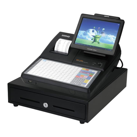
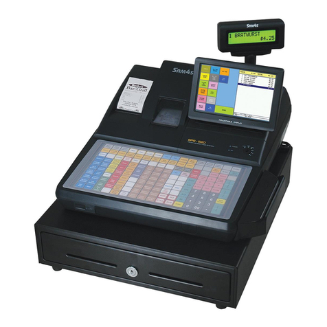
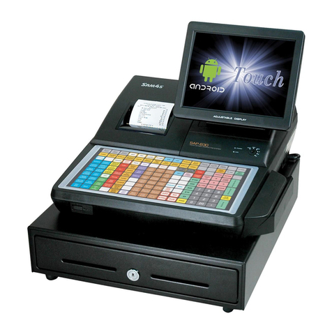
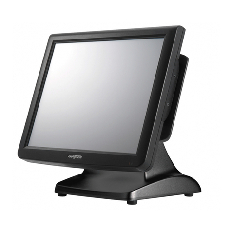
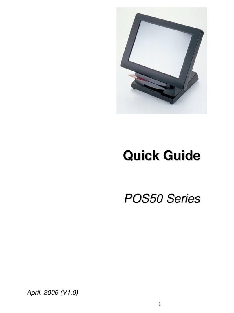
Sam4s SPS-500 User manual

SPS-500 Series C O N T E N T S
SPS-500 SERIES
POS SYSTEM
Manual
1. Precaution Statements
2. Product Specifications
3. Installation and Operation
4. Disassembly and Assembly
5. Maintenance and Adjustment
6. Troubleshooting
7. Exploded Views and Parts List
8. PCB Layout and Parts List
9. Wiring Diagram
10. Bock Diagram
11. Schematic Diagrams
SERVICE

Overview of this POS System
This service manual provides the technical information for many individual component systems and circuits and
gives an analysis of the operations performed by the circuits. Schematics and specifications provide the needed
information for the accurate troubleshooting.
All information in this manual is subject to change without prior notice. Therefore, you must check the
correspondence of your manual with your machine. No part of this manual may be copied or reproduced in any
form or by any means, without the prior written consent of Shin Heung Precision.
Note: Before using this POS system for the first time, leave it powered on in the REG mode for at least
twenty-four hours. This allows the Ni-MH battery, which maintains the memory of the POS while the
power is off, to charge completely. Proper disposal of batteries is required. Refer to your local
codes for disposal requirements.

About this Manual
This service manual describes how to
perform hardware service maintenance for
the SAM4S SPS-500 Series POS System
Notes
Notes may appear anywhere in the manual.
They describe additional information about
the item.
Precaution symbols
. Indicates a Safety Precaution that
applies to this part component.
. Indicates the part or component is an
electro-statically sensitive device. Use
caution when handling these parts.

Copyright
200ⓒ9 by Shin Heung Precision.
All right reserved.
This manual may not, in whole or in part, be
copied, photocopied, reproduced, translated
or converted to any electronic or machine
readable from without prior written
permission of Shin Heung Precision .
SAM4S SPS-500 SERIES
Aug. 2009.
V1.1
Printed in KOREA

SAM4S SPS-500 SERIES 1-1
1 Precaution Statements
Follow these safety, servicing and ESD precautions to prevent damage and to protect against potential hazards
such as electrical shock.
1-1 Safety Precautions
1. Be sure that all built-in protective devices are
replaced. Restore any missing protective
shields.
2. When reinstalling the chassis and its
assemblies, be sure to restore all protective
devices, including nonmetallic control knobs and
compartment covers.
3. Make sure there are no cabinet openings
through which people - particularly children -
might insert fingers and contact dangerous
voltages. Such openings include excessively
wide cabinet ventilation slots and improperly
fitted covers and drawers.
4. Design Alteration Warning:
Never alter or add to the mechanical or
electrical design of the POS. Unauthorized
alterations might create a safety hazard. Also,
any design changes or additions will void the
manufacturer’s warranty.
5. Components, parts and wiring that appear to
have overheated or that are otherwise damaged
should be replaced with parts that meet the
original specifications. Always determine the
cause of damage or over- heating, and correct
anypotentialhazards.
6. Observe the original lead dress, especially near
the following areas : sharp edges, and
especially the AC and high voltage supplies.
Always inspect for pinched, out-of-place, or
frayed wiring. Do not change the spacing
between components and the printed circuit
board. Check the AC power cord for damage.
Make sure that leads and components do not
touch thermally hot parts.
7. Product Safety Notice:
Some electrical and mechanical parts have
special safety-related characteristics which
might not be obvious from visual inspection.
These safety features and the protection they
give might be lost if the replacement component
differs from the original - even if the
replacement is rated for higher voltage, wattage,
etc.
Components that are critical for safety are
indicated in the circuit diagram by shading,
() or ( ). Use replacement components
that have the same ratings, especially for
flame resistance and dielectric strength
specifications. A replacement part that does
not have the same safety characteristics as the
original might create shock, fire or other
hazards.
CAUTION
Danger of explosion if battery is incorrectly replaced.
Replace only with the same or equivalent type
recommended by the manufacturer.
Dispose used batteries according to the
manufacturer’s instructions.
ATTENTION
ll y a danger d’explosion s’il y a remplacement
incorrect de la batterie.
Remplacer uniquement avec une batterie du même
type ou d’un type équivalent recommandé par le
constructeur.
Mettre au rebut les batteries usagées conformément
aux instructions du fabricant.

1 Precaution Statements
1-2 SAM4S SPS-500 SERIES
1-2 Servicing Precautions
WARNING: First read the-Safety Precautions-section of this manual. If some unforeseen circumstance creates
a conflict between the servicing and safety precautions, always follow the safety precautions.
WARNING: An electrolytic capacitor installed with the wrong polarity might explode.
1. Servicing precautions are printed on the cabinet.
Follow them.
2. Always unplug the units AC power cord from the
AC power source before attempting to:
(a) Remove or reinstall any component or
assembly (b) Disconnect an electrical plug or
connector (c) Connect a test component in
parallel with an electrolytic capacitor
3. Some components are raised above the printed
circuit board for safety. An insulation tube or
tape is sometimes used. The internal wiring is
sometimes clamped to prevent contact with
thermally hot components. Reinstall all such
elements to their original position.
4. After servicing, always check that the screws,
components and wiring have been correctly
reinstalled. Make sure that the portion around the
serviced part has not been damaged.
5. Check the insulation between the blades of the
AC plug and accessible conductive parts
(examples : metal panels and input terminals).
6. Insulation Checking Procedure:
Disconnect the power cord from the AC source
and turn the power switch ON. Connect an
insulation resistance meter (500V) to the blades
of AC plug.
The insulation resistance between each blade of
the AC plug and accessible conductive parts
(see above) should be greater than 1 megaohm.
7. Never defeat any of the B+ voltage interlocks.
Do not apply AC power to the unit (or any of its
assemblies) unless all solid-state heat sinks are
correctly installed.
8. Always connect an instrument’s ground lead to
the instrument chassis ground before connecting
the positive lead ; always remove the
instrument’s ground lead last.
1-3 Precautions for Electrostatically Sensitive Devices (ESDs)
1. Some semiconductor (solid state) devices are easily
damaged by static electricity. Such components are
called Electrostatically Sensitive Devices (ESDs);
examples include integrated circuits and some field-
effect transistors. The following techniques will reduce
the occurrence of component damage caused by static
electricity.
2. Immediately before handling any semiconductor
components or assemblies, drain the electrostatic
charge from your body by touching a known earth
ground. Alternatively, wear a discharging wrist-strap
device. (Be sure to remove it prior to applying power -
this is an electric shock precaution.)
3. After removing an ESD-equipped assembly, place it
on a conductive surface such as aluminum foil to
prevent accumulation of electrostatic charge.
4. Do not use freon-propelled chemicals. These can
generate electrical charges that damage ESDs.
5. Use only a grounded-tip soldering iron when soldering
or unsoldering ESDs.
6. Use only an anti-static solder removal device. Many
solder removal devices are not rated as anti-static;
these can accumulate sufficient electrical charge to
damage ESDs.
7. Do not remove a replacement ESD from its protective
package until you are ready to install it. Most
replacement ESDs are packaged with leads that are
electrically shorted together by conductive foam,
aluminum foil or other conductive materials.
8. Immediately before removing the protective material
from the leads of a replacement ESD, touch the
protective material to the chassis or circuit assembly
into which the device will be installed.
9. Minimize body motions when handling unpackaged
replacement ESDs. Motions such as brushing clothes
together, or lifting a foot from a carpeted floor can
generate enough static electricity to damage an ESD.
SAM4S SPS-500 SERIES 2-1
2 Product Specifications
[ SPS-520 PART ]
Specifications are correct at the time of printing.
Product specifications are subject to change without notice. See below for product specifications.
2-1 General Specifications
Item Description Remark
Processor S3C2440 (SEC)
Memory
BIOS :FLASH1MByte
SYSTEM :64MByteSDRAM
DATA :2MByte
[option : 6MByte] =>Total : 8MByte
Battery
Type : Lithium, 3V 65mAh
Charging Time : 24 Hours
Life : 3 Years
Data Storage 90 Days When battery is Full
charged
Interface Serial
(RS-232C)
Flow Control :
① DTR / DSR : H/W Flow Control
② XON / XOFF : S/W Flow Control
Baud Rate : 1200/2400/9600/19200/38400/57600/115200 Bps
Voltage Supply : VCC(+5V/1A) supplies at RS-232C#1~#4
RS-232C #1(DSUB-9)
RS-232C #2(DSUB-9)
RS-232C #3(RJ45)
RS-232C #4(RJ45)
LAN 10/100 base-T
ETHERNET(TCP/IP, 32REG)
SD CARD 1-Slot(2GByte_max)
MSR 1-Slot [option]
DRAWER 3-PORT [Default (internal) #1 / RJ-45 #2,#3]
i-BUTTON Magnetic [option]
USB 2-Port [HOST]
Printer
Model : STM-210II (Shinheung)
Printing Speed : 80mm / Sec
Detail Spec refer to Next
Page
Auto Cutter
Type : Guillotine
Cutting Method : 1 Point Partial Cutting
Display
Operator Display : 7” TFT-LCD(800*480)
Customer Display : 16char*2line LCD
Key Board
Flat Rubber Key : 160 Key
Raised Key : 90Key
Power Consumption Approx. 40W (Regularity)
Power Requirement AC 100~240V 50/60Hz [AC/DC Adaptor(24V/2.5A) Internal]
Environment
Condition
Temperature : 0℃~ 45℃
humidity : 30% ~ 80% RH
Weight Approximately 12Kg (Net)
Dimensions(mm)
430(W) ×468(L) ×344(H) : With A+ Drawer
400(W) ×468(L) ×344(H) : With G Drawer Set Size
Table2-1 General Specifications (SPS-520)

2 Product Specifications
2-2 SAM4S SPS-500 SERIES
2-2 Appearance
2-2-1 Appearance Dimensions (mm)
Figure2-1 Dimensions (SPS-520)
2-2-2 Location Features
Figure2-2 Location Features (SPS-520)
① Printer Cover
② SD Card
③ Key Board
④ USB
⑤ Drawer
⑥ Customer LCD Display (16char*2line LCD)
⑦ Operator LCD Display(7” TFT-LCD(800*480))
⑧ Mode Key
⑨ MSR
⑩ Dallas Key (i-BUTTON)
430(W) : With A+ Drawer
400(W) : With G Drawer

2 Product Specifications
SAM4S SPS-500 SERIES 2-3
2-3 Thermal Printer Specifications
2-3-1 Printer Specification (2”)
Item Description Remark
Model STM-210II ShinHeung Precision
Print Method Thermal Line Printing
Total Number of Dots 384 Dots / I Line
Printing Format
Dot Pitch
Vertical : 0.125 mm
Horizontal : 0.125 mm
Printing Speed 80 mm/Sec ( At 24V of Motor Voltage)
Printing Direction Unidirectional Friction Feed
Feeding Method Friction Feed
Minimum Feed Pitch 0.0625 mm
Paper Feeding
Feeding Speed 80 mm/Sec (At 24V of Motor Voltage)
Power Voltage 24V / 24V (Recommend) Head/Motor
Power Supply Volt
Circuit Input Voltage 5V Head Control/Sensor
Heat Element Density 8 Dots/mm (200dpi)
Total Head Elements 384 Dots / Dot Line
Available Printing Width 48 mm
Printer Head
Heat Element Typical Ω1500 Ω±3%
Line Feed Motor 4-Phase Uni-Polar Stepping Motor
Head Temperature Thermistor
Paper-End Sensor Reflecting Photo Sensor
Sensor
Printer Cover Open Sensor Micro Switch
Auto Cutter Type Guillotine Type Shin Heung Precision
MCBF 30,000,000 Lines
Reliability
Auto-cutter 1,000,000 Cuts
Dimension (mm) 82.5 (W) ×147.3 (D) ×101.4 (H)
Weight Approx. 365 g
Table2-2 Thermal Printer Specifications (SPS-520)

2 Product Specifications
2-4 SAM4S SPS-500 SERIES
2-3 Thermal Printer Specifications
2-3-2 Paper Specification
Item Description Remark
Paper Type Single-ply Thermal Paper Roll
Paper Size 57.5 mm±0.5 mm (Width) ×80 mm or less
Specified Paper Original Paper No : HPK-110 (Hansol paper XT)
Table2-3 Paper Specification (SPS-520)
Note: The following paper can be used instead of the specified paper above.
TF50KS-E: Nippon paper industries Co.,Ltd.
PD 160R : New Oji paper Mfg, Co.,Ltd.
F380 : Kansaki specialty papers, Inc. (USA)
2-3-3 Printable Area
The Printable area of a paper with width of 57.5mm is 48mm(384 dots) and the space on the right and left
sides are approximately 4.75mm.
Figure2-3 Printable Area (SPS-520)
2-3-4 Character Specification
Item Description Remark
Character Structure 12(W) ×24(H) Font (Including a Horizontal)
Character Size 1.25 mm(W) ×3.0 mm(H)
Column Pitch 1.5 mm
Line Pitch 3.75 mm (Including 6-dot Line Spacing)
Number of Column 32 (12×24 Dots/Character)
Table2-4 Character Specification (SPS-520)
b
cd e
a a = 57.5±0.5
mm
(Paper Width)
b = 0.125
mm (
1 Dot
)
c = 48
mm
(384 Dots/Printable Area)
d = 4.75
mm
(Left Space)
e = 4.75
mm
(Right Space)

2 Product Specifications
SAM4S SPS-500 SERIES 2-5
[ SPS-530 PART ]
Specifications are correct at the time of printing.
Product specifications are subject to change without notice. See below for product specifications.
2-1 General Specifications
Item Description Remark
Processor S3C2440 (SEC)
Memory
BIOS :FLASH1MByte
SYSTEM :64MByteSDRAM
DATA :2MByte
[option : 6MByte] =>Total : 8MByte
Battery
Type : Lithium, 3V 65mAh
Charging Time : 24 Hours
Life : 3 Years
Data Storage 90 Days When battery is Full
charged
Interface Serial
(RS-232C)
Flow Control :
③ DTR / DSR : H/W Flow Control
④ XON / XOFF : S/W Flow Control
Baud Rate : 1200/2400/9600/19200/38400/57600/115200 Bps
Voltage Supply : VCC(+5V/1A) supplies at RS-232C#1~#4
RS-232C #1(DSUB-9)
RS-232C #2(DSUB-9)
RS-232C #3(RJ45)
RS-232C #4(RJ45)
LAN 10/100 base-T
ETHERNET(TCP/IP, 32REG)
SD CARD 1-Slot(2GByte_max)
MSR 1-Slot [option]
i-BUTTON Magnetic [option]
DRAWER 3-PORT [ Default (internal) #1 / RJ-45 #2,#3]
USB 2-Port [HOST]
Printer Model : LTPF347E(SII)
Printing Speed : 100mm / Sec
Detail Spec refer to Next
Page
Auto Cutter Type : Guillotine
Cutting Method : 1 Point Partial Cutting
Display Operator Display : 7” TFT-LCD(800*480)
Customer Display : 16char*2line LCD
Key Board Flat Rubber Key : 160 Key
Raised Key : 90Key
Power Consumption Approx. 40W (Regularity)
Power Requirement AC 100~240V 50/60Hz [AC/DC Adaptor(24V/2.5A) Internal]
Environment
Condition
Temperature : 0℃~ 45℃
humidity : 30% ~ 80% RH
Weight Approximately 12Kg (Net)
Dimensions(mm) 430(W) ×468(L) ×344(H) : With A+ Drawer
400(W) ×468(L) ×344(H) : With G Drawer
Set Size
Table2-5 General Specifications (SPS-530)

2 Product Specifications
2-6 SAM4S SPS-500 SERIES
2-2 Appearance
2-2-1 Appearance Dimensions (mm)
Figure2-4 Dimensions (SPS-530)
2-2-2 Location Features
Figure2-5 Location Features (SPS-530)
430(W) : With A+ Drawer
400(W) : With G Drawer
① Printer Cover
② SD Card
③ Key Board
④ USB
⑤ Drawer
⑥ Customer LCD Display (16char*2line LCD)
⑦ Operator LCD Display(7” TFT-LCD(800*480))
⑧ Mode Key
⑨ MSR
⑩ Dallas Key (i-BUTTON)

2 Product Specifications
SAM4S SPS-500 SERIES 2-7
2-3 Thermal Printer Specifications
2-3-1 Printer Specification (3”)
Item Description Remark
Model LTPF347E SII
Print Method Thermal Line Printing
Total Number of Dots 576 Dots / I Line
Printing Format
Dot Pitch
Vertical : 0.125 mm
Horizontal : 0.125 mm
Printing Speed 100 mm/Sec
Printing Direction Unidirectional Friction Feed
Feeding Method Friction Feed
Minimum Feed Pitch 0.0625 mm
Paper Feeding
Feeding Speed 100 mm/Sec
Power Voltage 24V/24V (Recommand) Head/Motor
Power Supply Volt
Circuit Input Voltage 5V Head Control/Sensor
Heat Element Density 8 Dots/mm (200dpi)
Total Head Elements 576 Dots/Dot Line
Available Printing Width 72 mm
Printer Head
Heat Element Typical Ω1500 Ω ±3%
Line Feed Motor 4-Phase Bi-Polar Stepping Motor
Head Temperature Thermistor
Paper-End Sensor Reflecting Photo Sensor
Sensor
Printer Cover Open Sensor Micro Switch
Auto Cutter Type Guillotine Type SII
TPH 100Km , 1×10⁸ Pulses
Reliability
Auto-cutter 1,000,000 Cuts
Paper : PD-160R-N
(Oji paper co.,Ltd)
Dimension (mm) 110.2 (W) ×54 (D) ×25.8 (H)
Weight Approx. 175 g
Table2-6 Thermal Printer Specifications (SPS-530)

2 Product Specifications
2-8 SAM4S SPS-500 SERIES
2-3 Thermal Printer Specifications
2-3-2 Paper Specification
Item Description Remark
Paper Type Single-ply Thermal Paper Roll
Paper Size 79.5 mm±0.5 mm (Width) ×80 mm or less
Specified Paper Original Paper No : HPK-110 (Hansol paper XT)
Table2-7 Paper Specification (SPS-530)
Note: The following paper can be used instead of the specified paper above.
TF50KS-E: Nippon paper industries Co.,Ltd.
PD 160R : New Oji paper Mfg, Co.,Ltd.
F380 : Kansaki specialty papers, Inc. (USA)
2-3-3 Printable Area
The Printable area of a paper with width of 79.5mm is 72.0mm(576 dots) and the space on the right and left
sides are approximately 4.0mm.
Figure2-6 Printable Area (SPS-530)
2-3-4 Character Specification
Item Description Remark
Character Structure 12(W) ×24(H) Font (Including a Horizontal)
Character Size 1.25 mm(W) ×3.0 mm(H)
Column Pitch 1.5 mm
Line Pitch 3.75 mm (Including 6-dot Line Spacing)
Number of Column 32 (12×24 Dots/Character)
Table2-8 Character Specification (SPS-530)
b
cd e
a a = 79.5±0.5
mm
(Paper Width)
b = 0.141
mm (
1 Dot
)
c = 72.0
mm
(576 Dots/Printable Area)
d = 4.0
mm
(Left Space)
e = 4.0
mm
(Right Space)

2 Product Specifications
SAM4S SPS-500 SERIES 2-9
2-4 Power Specifications
2-4-1 Power Specification
Item Description Remark
Input Voltage &
Current
AC 100~240V, 800mA, 50/60Hz (Min : 90V, Max : 264V)
[AC/Dc Adaptor(24V/2.5A) Internal]
Power Consumption Peak : 50W
Table2-9 Power Specification
2-5 Interface Specifications
2-5-1 RS-232C Serial Interface Specification
Item Description Remark
Data Transmission Serial Data Transmission
Synchronization Asynchronous
Hand Shaking
(Flow Control)
H/W : DTR / DSR
S/W : XON / XOFF
XON : ASC Code 11h
XOFF : ASC Code 13h
Signal Level
Logic”1” (MARK) : -3V ~ -15V
Logic”0” (SPACE) : +3V ~ +15V
Baud Rate 2400 / 9600 / 19200 / 38400 / 57600 / 115200 bps Default 9600 bps
Data Word Length 7 Bit / 8 Bit
Parity None / Even / Odd
Connector
DB9P Male : COM#1, COM#2
RJ-45 Modular Jack : COM#3, COM#4
Voltage Supply
VCC(+5V/1A):COM#1~#4
VCC(+5V/1A):USB#1~#2
Table2-10 RS-232C Serial Interface Specification
CAUTION :
“VCC” is supplied for the Barcode or other devices. Supply current 1A is total value including COM#1~COM#4.
If the Total Power Consumption exceeds specification (1A), the system cuts “VCC” of COM#1~COM#4.
“VCC “ is supplied for the USB Device. Supply current 1A is total value including USB1#~USB#2.
If the total Power Consumption exceeds specification 1A, the system cuts “VCC” of USB#1~USB#2.

2 Product Specifications
2-10 SAM4S SPS-500 SERIES
2-5 Interface Specifications
2-5-2 RS-232C Signal Description
PIN NO
DSUB9(CN1) RJ45(CN3) Signal Name Direction Function
1 - DCD IN Carrier Detect
2 4 RXD IN Receive Data
3 3 TXD OUT Transmit Data
4 DTR OUT Data Set Ready
5 7 GND - -
6 DSR IN Data Terminal Ready
7 8 RTS OUT Request To Send
8 2 CTS IN Clear To Send
RI IN
Ring Indicator
9 1 +5V/500mA -
Total Power : 1A (COM#1,#2 : Pin9, COM#3 ,#4 : Pin1 )
-

2 Product Specifications
SAM4S SPS-500 SERIES 2-11
2-5 Interface Specifications
2-5-3 RS-232C Interface Cable
SPS-500 SIDE
(DSUB9 FEMALE)
(+5V)
(COM1, COM2 I/F CABLE PIN CONNECTION )
USER SIDE
(DSUB25 MALE)
SPS-500 SIDE
(DSUB9 FEMALE)
(+5V)
( COM1, COM2 I/F CABLE PIN CONNECTION )
USER SIDE
(DSUB9 MALE)
CAUTION :
COM#1~COM#2 supplies “+5V” to DSUB9 “Pin Num 9”.
15m
15m

2 Product Specifications
2-12 SAM4S SPS-500 SERIES
2-5 Interface Specifications
2-5-3 RS-232C Interface Cable
SPS-500 SIDE
5(RTS)
6(CTS)
3(TXD)
7(S.GND)
2(DSR)
7(RTS)
8(CTS)
5(S.GND)
3(TXD)
4(DTR)
8(DTR)
4(RXD)
6(DSR)
2(RXD)
( COM3, COM4 I/F CABLE PIN CONNECTION )
USER SIDE
(DSUB9 MALE)
SPS-500 SIDE
5(RTS)
7(S.GND)
8(DTR)
3(TXD)
4(RXD)
4(RTS)
7(S.GND)
6(DSR)
2(TXD)
3(RXD)
6(CTS)
2(DSR)
5(CTS)
20(DTR)
( COM3, COM4 I/F CABLE PIN CONNECTION )
USER SIDE
(DSUB25 MALE)
CAUTION :
COM#3~COM#4 supplies “+5V” to RJ45 “Pin Num 1”.
15m
15m

2 Product Specifications
SAM4S SPS-500 SERIES 2-13
2-5 Interface Specifications
2-5-4 USB Interface Specification
Item Description Remark
Transfer Type ●BULK
Data Signal
●Bi-Direction, Half-Duplex
●Differential Signal Pair (D+ / D-)
Data Format
●NRZI Format
●Zero Bit Stuffing after 6 Ones
Transceiver
●Differential Common Mode Range : 0.8 ~ 2.5[V]
●Differential Receive Sensitivity : 200[mV]
●Single End Receive Threshold : 0.8 ~ 2.5[V]
Speed ●12Mbps
Power ●Supply 5V/500mA (For HID)
Cable & Connector
●Cable :5m/2m
●Connector :A type
Support Spec ●USB Spec Version 1.1
2-5-5 USB Signal Description
Pin No Signal Name Color Function
SHELL Shield Drain Wire Frame GND
1 VBUS Red Host Power : DC5[V] / 500[mA]
2 D- White Differential Data Line
3 D+ Green Differential Data Line
4 GND Black Signal GND
2-5-6 USB Interface Cable
SPS-500 SIDE
"A" TYPE PLUG "B" TYPE PLUG
(USB I/F CABLE)
USER SIDE

2 Product Specifications
2-14 SAM4S SPS-500 SERIES
2-5 Interface Specifications
2-5-7 LAN (IRC) Signal Description
Pin No Signal Name Signal Direction Function
1 ENET TX+ OUT Ethernet Transmit Data Line(+)
2 ENET TX- OUT Ethernet Transmit Data Line(-)
3 ENET RX+ IN Ethernet Receive Data Line(+)
4 N.C -
5 N.C -
6 ENET RX- IN Ethernet Receive Data Line(+)
7 N.C -
8 N.C -
2-5-8 LAN (IRC) Interface Cable
SPS-500 SIDE
MAX 100M
5(N.C)
7(N.C)
8(N.C)
4(N.C)
5(N.C)
6(ENET RX-)
7(N.C)
1(ENET TX+)
2(ENET TX-)
3(ENET RX+)
6(ENET RX-)
1(ENET TX+)
2(ENET TX-)
3(ENET RX+)
4(N.C)
8(N.C)
( POS to POS IRC I/F CABLE )
7(N.C)
8(N.C)
6(ENET RX-)
7(N.C)
2(ENET TX-)
3(ENET RX+)
4(N.C)
6(ENET RX-)
4(N.C)
2(ENET TX-)
3(ENET RX+)
5(N.C)
1(ENET TX+)
8(N.C)
5(N.C)
1(ENET TX+)
(POS to HUB IRC I/F CABLE)
USER SIDE
Other manuals for SPS-500
8
This manual suits for next models
2
Table of contents
Other Sam4s Touch Terminal manuals

Sam4s
Sam4s SAP-630 Series User manual

Sam4s
Sam4s SAP-6600 User manual

Sam4s
Sam4s SAM4POS User manual

Sam4s
Sam4s SPS-500 User manual

Sam4s
Sam4s SAM4POS User manual

Sam4s
Sam4s SPT-7000 Series Guide

Sam4s
Sam4s Titan-560 User manual

Sam4s
Sam4s SPT-3000 Guide

Sam4s
Sam4s SPS-1000 Owner's manual

Sam4s
Sam4s SAP-6600II User manual