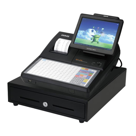
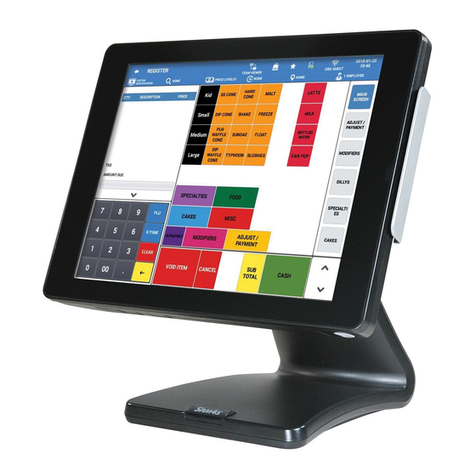
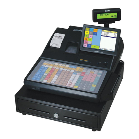
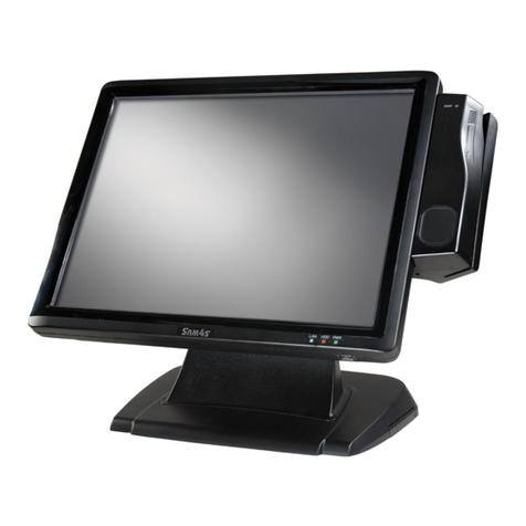
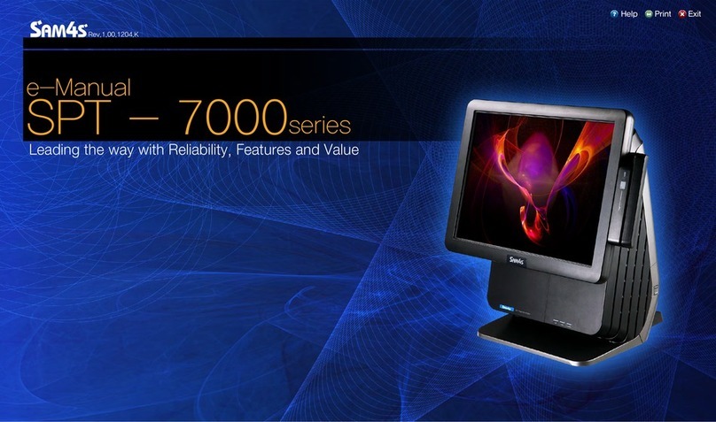
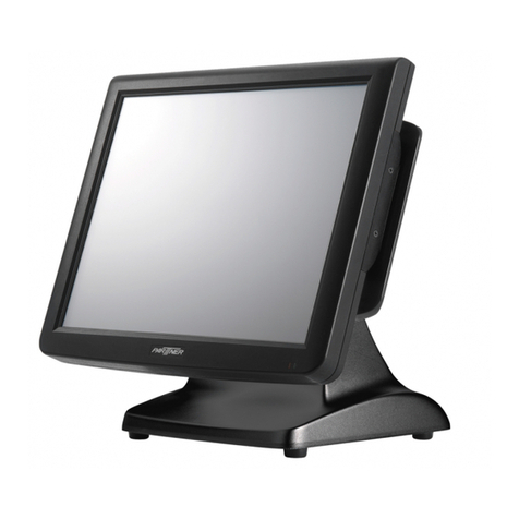
Sam4s SPT-3000 Guide


1-2
Unpacking
<Main body > <Mouse(Option)><Keyboard(Option) >
<Quick manual > <Magnetic Dallas(Option)> <Power Cable / Adoptor>
Help Printer Exit
Content
Introductions
Unpacking
Specification
Product overview
HOME
Getting Started
Using this system
Removal and
Replacement
BIOS Setup
How to use PDF
e-manual
Exploded View
and Replaceable
parts

1-
3
General Specification
Introductions
Unpacking
Specification
Product overview
HOME
Getting Started
Using this system
Removal and
Replacement
BIOS Setup
How to use PDF
e-manual
Exploded View
and Replaceable
parts
Dimension(mm)
387mm(W) × 278mm(L) × 340mm(H)
Di
mens
i
on
(
mm
)
38
7mm
(W)
×
2
7
8
mm
(L)
×
3
4
0
mm
(H)
Weight 5.8 Kg
CPU : Intel Atom Processor N270 1.6GHz(Onboard) Without FAN
P
FSB : 533MHz
Chip Sets Northbridge : Intel 945GSE
Southbridge : Intel ICH7M
Processor
HDD 2.5" SATA Type
Serial(RS-232) Connector : D-SUB 9Pin x 3(COM1,3,4) + RJ45 Port x 1(COM5)
COM1,3,4,5 --> 5V or 12V Output(Main Board DIP Switch Setting)
I/O Interface
,,, p ( g)
Serial(RS-422/485) Connector : D-SUB 9Pin x 1(COM1 Common Use : BIOS Setting)
Parallel Connector : D-SUB 25Pin x 1
USB 2.0 Connector : Left Side x 1, Rear Side x 4
LAN Connector : RJ45 Port x 1(8Pin)
Cash Drawer Connector : RJ11 Port x 1(6Pin)
Cash
Drawer
Connector
:
RJ11
Port
x
1(6Pin)
VGA Connector : VGA Port x 1(15pin)
Audio Connector : Line out x 1, MIC x 1
OS
(Operating System)
Windows XP / 2000 / WEPOS / …
(Operating
System)
Main Memory DDR2 533/667/800 SO-DIMM Slot, (Up to 2GB)
Booting Device HDD, External CD/DVD-ROM Drive, USB Memory
Help Printer Exit
Content

1-
4
Introductions
Unpacking
Specification
Product overview
HOME
Getting Started
Using this system
Removal and
Replacement
BIOS Setup
How to use PDF
e-manual
Exploded View
and Replaceable
parts
20Char × 2Line 5 × 7 Dot VFD or
Customer Display
20Ch
ar
×
2Li
ne,
5
×
7
D
o
t
VFD
or
256 × 32 Graphic Dot, 15" TFT LCD, XGA(1024 ×768)
MSR
Read Track : ISO Track 2&3 or ISO Track 1&2
Interface : USB
/
MSR
(Magnetic Stripe Reader) Performance : 10~150CM/Sec
Head Reliability : 500,000 times
Error Rate : Less than 0.5%
Wall Mount
Wall Mountable
Wall
Mount
Wall
Mountable
Dallas Key Magnet Type
Cash Drawer RJ11 Port(6pin) x 1, 12V or 24V (selection is possible)
BIOS
AMI(Amerian Megatrends Inc ) BIOS
BIOS
AMI(A
mer
i
an
M
e
g
atren
d
s,
I
nc.
)
BIOS
15" TFT LCD, LVDS Interface
Resolution & Colors : 1024x768(XGA), 16.2M(RGB) Color
Contrast Ratio : 450 : 1
Display Viewing Angle(H-V) : 150˚ / 130˚ (Left : 75˚, Right : 75˚, Up : 70˚, Down : 60˚)
Backlight Type : 2-CCFL
BacklightBrightness : 250 cd/㎡
Backlight MTBF : 50,000hrs
Touch Panel
15" 5-Wire Resistive Type
Type : Serial COM6
Transparency : 80%
Surface Hardness : 3H
Hitting Life : 35million times
Hitti
n
g
Lif
e
:
35
m
illi
on
ti
mes
Power Supply
100W Adapter
AC INPUT : AC 100~240V / 50~60Hz
DC OUTPUT : 12V /8.33A
Optional Specification
Help Printer Exit
Content

1-
6
Features names of Functions and each part
MSR(Magnetic Stripe Reader)
Card (Credit Card, Loyalty Card and so on)
can be recognized for transaction.
Hard Drive Light
When the Hard Drive is in operation, the light will be lit.
Power Light
When the system is on, the light will be lit.
STAND
Card Recognition Light
When the card is swiped correctly, the light will be lit.
Front View
Help Printer Exit
Content
Introductions
Unpacking
Specification
Product overview
HOME
Getting Started
Using this system
Removal and
Replacement
BIOS Setup
How to use PDF
e-manual
Exploded View
and Replaceable
parts

1-
7
Help Printer Exit
Content
Introductions
Unpacking
Specification
Product overview
HOME
Getting Started
Using this system
Removal and
Replacement
BIOS Setup
How to use PDF
e-manual
Exploded View
and Replaceable
parts
Bottom View
RJ11 Cash Drawer Port
Customer Display Port
DC Power Output Port
CF CARD
Audio Port
RJ45 LAN Port
USB Port
Dual Monitor Port
Serial Port
Parallel Port
DC Power Supply Port
Microphone Port

1-
8
..
USB
USB Devices can be used through this
port, i.e. USB scanner, USB Keyboard,
USB Printer, etc.
SD CARD SLOT
POWER BUTTON
LCD BRTGHTNESS
Screen Brightness can be altered.
CUSTOMER DISPLAY(CDP)
This shows the amount which Customers
have to pay
ANGLE ADJUSTMENT LEVER
Angle can be altered between 20 ~ 90 degree.
DUMMYDUAL MONTITOR EXPANSION COVER
Rear View
SD Card, MMC Card can be used.
(Option)
Turns On-Off your system
Help Printer Exit
Content
Introductions
Unpacking
Specification
Product overview
HOME
Getting Started
Using this system
Removal and
Replacement
BIOS Setup
How to use PDF
e-manual
Exploded View
and Replaceable
parts

2-1
Introductions
Safety Instructions
Connecting the
External Device
Turning the System
On and Off
Getting Started
Using this system
Removal and
Replacement
BIOS Setup
Exploded View
and Replaceable
parts
90。
50。 [STANDARD ANGLE]
20。
▶
Safety Instructions
Read the safety instructions carefully and thoroughly. All cautions and warnings on the equipment or user’s manual should be noted.
Lay this equipment on a stable surface before setting it up.
Keep this equipment away from humidity and high temperature.
Make sure the power voltage is within safety range and has been adjusted properly to the value of 100~240V before connecting
the equipment to the power outlet.
Always keep the strong magnetic or electrical objects away from the equipment.
Always unplug the power cord before conecting any External Devices. Never pour liquid into the opening that could damage
the equipment or cause an electrical shock.
The openings on the enclosure are used for air convection and to prevent the equipment from overheating. Do not cover the openings.
●
●
●
●
●
●
●
Adjust the angle of Display.
Screen angle can be adjusted for best viewing.
Note !
How to use PDF
e-manual
HOME
Removing the Cover
Cable
Help Printer Exit
Content

2-2
Before connecting Peripherals
Remove Cover Cable
❶
In case the screws of Cover Cable are fixed, remove them first.
❷
After removing screws, press hook of Cover Cable and remove.
Hook of Cover Cable
Introductions
Safety Instructions
Connecting the
External Device
Turning the System
On and Off
Getting Started
Using this system
Removal and
Replacement
BIOS Setup
Exploded View
and Replaceable
parts
How to use PDF
e-manual
HOME
Removing the Cover
Cable
Help Printer Exit
Content
Connecting Peripherals

2-3
Remove Cable Tidy Dummy by using (-) shaped driver. Depending upon the places,
the system can be used while Cable Tidy Dummy is removed.
Remove Cable Tidy Dummy
Dual Monitor Expansion Cover
In case there is not enough space for connecting Dual Monitor or Customer Display (Pole),
Dual Monitor Expansion Cover can be removed.
Cable Tidy Dummy
Dual Monitor Expansion
Cover
Introductions
Safety Instructions
Connecting the
External Device
Turning the System
On and Off
Getting Started
Using this system
Removal and
Replacement
BIOS Setup
Exploded View
and Replaceable
parts
How to use PDF
e-manual
HOME
Removing the Cover
Cable
Help Printer Exit
Content

2-4
Connect PS/2 type keyboard & mouse.
Connecting Peripherals
Connecting keyboard & mouse
The I/O ports on the POS-System allow you to connect peripheral devices. All device listed here are for reference only.
Connecting Printer
QBIG PC POS supports parallel, serial & USB typed printers.
Connect desired type of printer cable.
Introductions
Safety Instructions
Connecting the
External Device
Turning the System
On and Off
Getting Started
Using this system
Removal and
Replacement
BIOS Setup
Exploded View
and Replaceable
parts
HOME
Removing the Cover
Cable
Note !
System supplies upto 24V & 2.3A. In case the printer requires
above mentioned voltage & current, the power adapter should
be used.
How to use PDF
e-manual
Help Printer Exit
Content
<Receipt Printer>
Power Cable
for Printer

2-5
Introductions
Safety Instructions
Connecting the
External Device
Turning the System
On and Off
Getting Started
Using this system
Removal and
Replacement
BIOS Setup
Exploded View
and Replaceable
parts
How to use PDF
e-manual
HOME
Removing the Cover
Cable
Help Printer Exit
Content
5V
12V
Connect barcode scanner etc. to the serial port.
Connecting devices which uses the serial port
<Barcode Scanner>
Use RJ-11 port when Cash Drawer is desired & used
(Use SAM4S Cash Drawer).
Connecting RJ-11 Cash Drawer
<Cash Drawer>
PORT 5V 12V (RS422/RS485)
COM1 ○
COM3 X
COM4 X
○
○○
○○

2-6
Introductions
Safety Instructions
Connecting the
External Device
Turning the System
On and Off
Getting Started
Using this system
Removal and
Replacement
BIOS Setup
Exploded View
and Replaceable
parts
How to use PDF
e-manual
HOME
Removing the Cover
Cable
Help Printer Exit
Content
<LAN Hub>
<CCD Camera>
USB connector is located both the side of LCD panel and the back of the
system so USB devices can be connected at both locations. USB hub can
be used to connect various USB devices which includes keyboard, mouse,
CCD camera and printer etc. (separate device drivers may be required).
Connecting USB Device
RJ-45 LAN or Internet enabled cable can be connected.
It supports 10Mbps/100Mbps.
Connecting RJ-45 LAN cable
<Keyboard>
<Mouse>

2-7
Connecting DC power supply cable to the bottom of system.
(Free Voltage system adapter is used. Both 100V and 220V can be used.)
Connecting DC power supply cable.
Note !
QBig Adapter from SAM4S should only be used. Never
use the adapter with similar specification or shaped .
▶
Introductions
Safety Instructions
Connecting the
External Device
Turning the System
On and Off
Getting Started
Using this system
Removal and
Replacement
BIOS Setup
Exploded View
and Replaceable
parts
How to use PDF
e-manual
HOME
Removing the Cover
Cable
Help Printer Exit
Content

2-8
System On/Off
System On
After installation of system, proceed to power on the system with following steps.
1
2
3
4
Introductions
Safety Instructions
Connecting the
External Device
Turning the System
On and Off
Getting Started
Using this system
Removal and
Replacement
BIOS Setup
Exploded View
and Replaceable
parts
How to use PDF
e-manual
HOME
Removing the Cover
Cable
Help Printer Exit
Content
Power up the peripherals which are connected with the system.
Press the power button placed at the left side of system LCD (Open the power button cover and press).
PWR light is to be lit at the right bottom of the LCD front.
Windows initial screen can be seen after a while.
power bottom
power light

2-9
System Off
1
2
3
Introductions
Safety Instructions
Connecting the
External Device
Turning the System
On and Off
Getting Started
Using this system
Removal and
Replacement
BIOS Setup
Exploded View
and Replaceable
parts
How to use PDF
e-manual
HOME
Removing the Cover
Cable
Help Printer Exit
Content
System Off
All applications should be off after saving files in the designated place.
Press <Start> button and select 'Turn off Computer' on popup menu.
System will be shut down when <Turn Off> button is clicked.

Introductions
Touch Screen
Backup and Recovery
Driver and Utility
Dual Monitor
Getting Started
Using this system
HOME
Removal and
Replacement
BIOS Setup
Exploded View
and Replaceable
parts
How to use PDF
e-manual
Help Printer Exit
Content
Touch Screen
Recalibrate if it is not accurate on touch points.
Check Out Touch Scrrraemememedmdfmdm,drrreen
Click the right button of mouse on 'PM' icon of Windows tray icons.
And select 'Control Panel' on popup menu.
'PenMount Control Panel' dialog appears.
1
2
Check Out Touch Screen
Click the 'Tools' tab and check out whether or not 'Advanced Calibration'
option box is yellow-marked. If it is not yellow, click the 'Advanced
Calibration' button and return to 'Device' tab.
3-1

3-2
Help Printer Exit
Content
ibration
Double-click 'PenMount 9000 RS232' on 'Device' Tab.
1
On 'Calibrate' tab, select the number '25' of Advanced Mode combo-box list if it is possible.
And then click the 'Advanced Calibration' button.
(The number of box is higher and higher, calibration will be more accurate.)
2
Touch Screen Calibration
Introductions
Touch Screen
Backup and Recovery
Driver and Utility
Dual Monitor
Getting Started
Using this system
HOME
Removal and
Replacement
BIOS Setup
Exploded View
and Replaceable
parts
How to use PDF
e-manual

Help Printer Exit
Content
3-3
Click the red point about 2 seconds on a calibration screen. Calibration procedure will be proceeded with following messages.
3
Ball point pen or sharpness tools may damage to surface of touch screen.
Caution
Introductions
Touch Screen
Backup and Recovery
Driver and Utility
Dual Monitor
Getting Started
Using this system
HOME
Removal and
Replacement
BIOS Setup
Exploded View
and Replaceable
parts
How to use PDF
e-manual

3-4
Help Printer Exit
Content
❶❷
❸.❹
Help Printer Exit
Content
Note !
For using the Touch Screen on Multi-monitor.
Check 'Multiple Monitor Support' box on 'Multiple Monitors' tab. Click <Map Touch Screens> button.
Click <OK> button on 'Mapping' message box. If you want to use touchable screen of current monitors, you shoud
touch the screen. If or not,press 'S' to skip.
For more detailed information about using dual monitor, refer to 'Dual Monitor' pages.
Introductions
Touch Screen
Backup and Recovery
Driver and Utility
Dual Monitor
Getting Started
Using this system
HOME
Removal and
Replacement
BIOS Setup
Exploded View
and Replaceable
parts
How to use PDF
e-manual
Table of contents
Other Sam4s Touch Terminal manuals

Sam4s
Sam4s SAP-630 Series User manual

Sam4s
Sam4s Touch Screen Terminal User manual

Sam4s
Sam4s SAM4POS User manual

Sam4s
Sam4s SPT-7000 Series Guide

Sam4s
Sam4s SAM4POS User manual

Sam4s
Sam4s SAP-6600 User manual

Sam4s
Sam4s SPS-500 User manual

Sam4s
Sam4s SAP-6600II User manual

Sam4s
Sam4s SPS-1000 Owner's manual

Sam4s
Sam4s SPS-500 User manual
Popular Touch Terminal manuals by other brands

Elproma
Elproma RB865io user manual

Ingenico group
Ingenico group AXIUM DX8000-BASE-W2 user guide

Tone Commander
Tone Commander NT1B-300TC-TSG installation instructions

HP
HP Rp3000 - Point of Sale System Getting started guide

Worth Data
Worth Data 7100 Series Quick start and installation guide

Clover
Clover Mini install guide