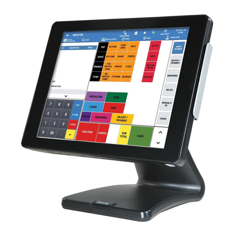
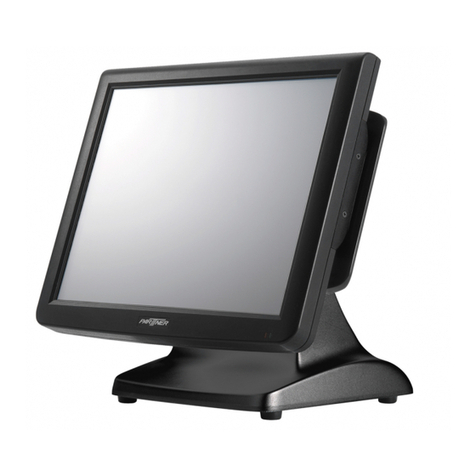
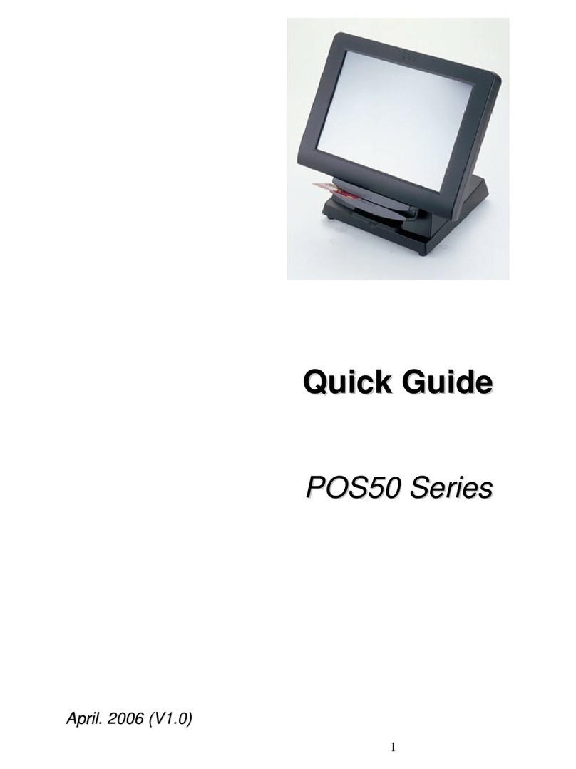
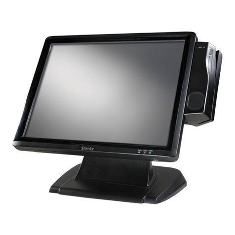
Sam4s SPT-7000 Series Guide

Leading the way with Reliability, Features and Value
SPT - 7000series
e-Manual
Help Print Exit
?
Rev.1.00.1204.K

HOME Contents Help Print Exit
?
Introduction
Notification
Notification
References
Alert massage & symbol
Unpacking
System Features
Part Name and Function
System Installation
System Use
System Expansion
& Dismantle
Appendix A
System Set-Up
Appendix B
System Structure
▶
▶
▶
▼
SPT-7000
This e-Manual provides you with technical information such as electrical circuit, components and structure regarding Sam4s POS (Point of Sale) System SPT-7000.
The outer design or specifications are subject to change for quality improvement without prior notice.
[Notice to Users]
This device classified for the commerce is compatible with A-Class Electromagnetic Wave Registration.
So, it is recommended to be used in shops or stores outside households.
Thank you for your purchase of Sam4s POS terminal.
01. Notificaton
References
Introduction
◀ 1 - 1 ▶
How to use e-Manual
Show all titles of of e-Manual
Exit PDF e-Manual
Print e-Manual page
Move to the next page.
Page Number
Move to the previous page.
Click these text button to move each chapter
Move to the first page
Help Contnets
Introduction
System Installation
System Use
System Expansion
& Dismantle
Appendix A
System Set-Up
Appendix B
System Structure
▶
▶
▶
SPT-7000
HOME Contents Help Print Exit
?

Introduction
Notification
Notification
References
Alert massage & symbol
Unpacking
System Features
System Introduction
System Features
System Specifications
Part Name and Function
Front View
Half-Side View
Side View
Rear View
▼
System Installation
Make sure of
installation area
Before connecting
peripherals
Connecting Peripherals
Connecting Serial Port Devices
such as Barcode Scanner
Connecting RJ-11 Cash Drawer
Connecting RJ-45 LAN Cable
Connecting USB Device
Connecting PS Module
Connecting Security
/ Scanner Module
Connecting Receipt Printer
Receipt Printer
Dismantle the Cover
for Customer Displays
Connecting DVR Card
Connecting AC Power
Cord to the Set Plug
Cable Management
System On / Off
System On
System Off
▼
System Use
Keyboard Use
Touch screen Use
About POS
Driver and Utility
Dual Monitor Use
▼
System Expansion
& Dismantle
System Dismantling
& Assembling
HDD Replacement
Internal Speaker
& USB Removal
Receipt Printer
& Board Removal
Scanner
& Dallas Removal
SMPS Removal
Mainboard ASSY Removal
Various Boards Removal
Main Memory Removal
Remove Display Assembly
Remove MSR
Remove Display Board
Remove Touch Panel & LCD
▼
Appendix A
System Set-Up
System Set-up Preview
Main Menu
Advanced Menu
Chipset Menu
Boot Menu
Security Menu
Save & Exit Menu
▼
Appendix B
System Structure
System Block
Mainboard Overview
Exploded View
▼
Contents
PDF electronic manual consists of System Instruction, System Installation, System Use, System Setup, System Expansion and Appendix a/b.
SPT-7000series
E-Manual
HOME Contents Help Print Exit
?

Introduction
Notification
Notification
References
Alert massage & symbol
Unpacking
System Features
Part Name and Function
System Installation
System Use
System Expansion
& Dismantle
Appendix A
System Set-Up
Appendix B
System Structure
▶
▶
▶
▼
SPT-7000
References
This e-Manual provides you with technical information such as electrical circuit, components and structure regarding Sam4s POS (Point of Sale) System SPT-7000.
The outer design or specifications are subject to change for quality improvement without prior notice.
[Notice to Users]
This device classified for the commerce is compatible with A-Class Electromagnetic Wave Registration.
So, it is recommended to be used in shops or stores outside households.
◀ 1 - 1 ▶
Thank you for your purchase of Sam4s POS terminal.
HOME Contents Help Print Exit
?
01. Notificaton
Introduction

◀ 1 - 2 ▶
The contents of this manual is subject to change without prior notice.
This manual cannot be copied or duplicated without Sam4s approval.
The copyright of the e-Manual is in Sam4s.
Some equipment nomenclature and abbreviations used here may differ from that contained in other Sam4s publications.
This device complies with part 15 of the FCC Rules. (Class A digital device)
References
Introduction
Notification
Notification
References
Alert massage & symbol
Unpacking
System Features
Part Name and Function
System Installation
System Use
System Expansion
& Dismantle
Appendix A
System Set-Up
Appendix B
System Structure
▶
▶
▶
▼
SPT-7000
HOME Contents Help Print Exit
?
01. Notificaton
Introduction

This indicates a hazardous situation likely to result in serious personal injury if the user does not perform the procedure correctly.
This indicates a hazardous situation could result in personal injury if the user does not perform the procedure correctly.
This indicates a hazardous situation could result in minor or moderate personal injury if the user does not perform the procedure correctly.
This alert signal also indicates that damages to the product or other property may occur if the user does not perform the procedure correctly.
This indicates information that could help the user use the product more efficiently.
This manual uses the following conventions to show the alert messages. An alert message consists of an alert signal and alert statements.
The alert signal consists of an alert symbol and a signal word or just a signal word. The following are the alert signals and their meanings:
◀ 1 - 3 ▶
Introduction
Notification
Notification
References
Alert massage & symbol
Unpacking
System Features
Part Name and Function
System Installation
System Use
System Expansion
& Dismantle
Appendix A
System Set-Up
Appendix B
System Structure
▶
▶
▶
▼
SPT-7000
Alert massage & symbol
01. Notificaton
Introduction
HOME Contents Help Print Exit
?

02. Unpacking
Introduction
<System Terminal>
<Mouse / Mouse Pad (Option)> <Keyboard (Option)>
<Quick Manual> <Power Cable>
◀ 1 - 4 ▶
Introduction
Notification
Unpacking
System Features
Part Name and Function
System Installation
System Use
System Expansion
& Dismantle
Appendix A
System Set-Up
Appendix B
System Structure
▶
▶
▶
▼
SPT-7000
HOME Contents Help Print Exit
?

◀ 1 - 5 ▶
Introduction
Notification
Unpacking
System Features
System Introduction
System Features
System Specifications
Part Name and Function
System Installation
System Use
System Expansion
& Dismantle
Appendix A
System Set-Up
Appendix B
System Structure
▶
▶
▶
▼
SPT-7000
03. System Features
System Introduction
Introduction
System Features
This POS system supports All-in-one type and Separable type. Also, you can organize the cables easily in any surrounding.
This POS system can make all-in-one touch screen, internal printer, MSR, SCR and customer display. And installation is easy and convenient.
It is convenient to change Hard Disk Drive and Memory and supports OS recovery function and Virus Vaccine program.
◀ 1 - 5 ▶
TFT LCD Touch Screen
Internal Printer (Option)
MSR (Magnetic Stripe Reader) (Option)
SCR (Smart Card Reader) (Option)
Size Customer Display (Option)
Barcode Scanner (Option)
Fingerprint Reader or Magnet Dallas (Option)
Cfast Module (Option)
HOME Contents Help Print Exit
?

System Specifications
03. System Features
Introduction
◀ 1 - 6 ▶
Dimension
Weight
Processor
Chipset
Storage
I/O Interface
OS
Main Memory
Booting Device
BIOS
267(357) X 310 X 387(447) ( ):With Display
11.5 Kgs (based on standard specification)
CPU : Intel Atom Cedarview D2550 1.86GHZ (Dual Core) FANLESS HEAT SINK
Southbridge : Intel NM10
2 x 2.5 inch HDD (SATA type) / SSD / Cfast
Serial Connector : DSUB 9-pin x 3 (COM1,2,4)+RJ45 port x 1 (COM3)
COM1,2,3,4 : 5V or 12V or RI Output (BIOS setting)
Parallel Connector : 25-pin x 1
USB 2.0 Connector : Left Side x 2, Rear Side x 4
LAN Connector : RJ45 port x 1 (8-pin)
Cash Drawer : RJ11 port x 1 (6-pin)
VGA Connector : VGA port x 1 (15-pin)
DC Output Jack : 12V output port x 1
Audio : Line Out x 1, Line In x 1, MIC x 1
Windows XP / 2000 / WEPOS 등 / POSReady 2009 / POSReady 7
DDR3 SODIMM Socket (up to 4GB)
HDD, SSD, Cfast Memory, CD/DVD ROM Drive, USB Memory
AMI(Amerian Megatrends, Inc.) BIOS
General Specifications
Introduction
Notification
Unpacking
System Features
System Introduction
System Features
System Specifications
Part Name and Function
System Installation
System Use
System Expansion
& Dismantle
Appendix A
System Set-Up
Appendix B
System Structure
▶
▶
▶
▼
SPT-7000
HOME Contents Help Print Exit
?

◀ 1 - 7 ▶
TFT LCD, LVDS Interface
Resolution & Colors : 1024 x 768 (XGA), 16.2M (RGB) Color
Contrast Ratio : 450 : 1
Viewing Angle : Left-Right / Up-Down (Left / Right / Up / Down )
Backlight Type : 2-CCFL
Backlight Brightness : 250 cd/㎡
Backlight MTBF : 50,000 Hours
5-Wire Resistive Type
Interface : Serial COM5
Transparency : 80%
Surface Hardness : 3H
Hitting Life : 35 million times
60W Adaptor
AC INPUT : AC 100~240V / 50~60Hz, 1.5A
DC OUTPUT : 12V / 5.0A
Display
Touch Panel
Power Supply
System Specifications
General Specifications
Introduction
Notification
Unpacking
System Features
System Introduction
System Features
System Specifications
Part Name and Function
System Installation
System Use
System Expansion
& Dismantle
Appendix A
System Set-Up
Appendix B
System Structure
▶
▶
▶
▼
SPT-7000
HOME Contents Help Print Exit
?
03. System Features
Introduction

◀ 1 - 8 ▶
2-inch / 3-inch Thermal Printer
USB Interface
220mm/sec (3-inch), 150mm/sec (2-inch) speed
180 dpi resolution
Guillotine Type Auto-Cut (Jam-free)
True Flat Resistive Touch
Read Track : ISO Track 1&2&3
Interface : USB
Performance Speed : 630BPS ~ 11,550BPS
Head Reliability : 400,000 times
Magnet Type
Fingerprint function, USB Commuication
Possible to use Cfast Memory
Various types of DVR Card installable including XV400PCI (Max. Channel 4 ports)
1D Barcode Recognition, USB Commuication
IC Card readable, USB Commuication
Power Supply
60W Adaptor
AC INPUT : AC 100V ~ 240V / 50Hz ~ 60Hz 1.5A
DC OUTPUT : 24V / 2.5A
Receipt Printer
Touch Panel
Customer Display
MSR (Magnetic Stripe Reader)
DALLAS KEY
Finger Printer Reader
Cfast SOCKET
RAISER CARD
Scanner
Smart Card Reader
TFT LCD, VGA (800 480)
TFT LCD, XGA(1024 768)
- Power Supply Change
80W Adaptor
AC INPUT : AC 100V ~ 240V / 50Hz ~ 60Hz 1.5A
DC OUTPUT : 12V / 6.67A
20 CHAR 2Line
5 7 Dot VFD
256 32 Graphic Dot,
CDP
System Specifications
Specifications for Optional Devices
Introduction
Notification
Unpacking
System Features
System Introduction
System Features
System Specifications
Part Name and Function
System Installation
System Use
System Expansion
& Dismantle
Appendix A
System Set-Up
Appendix B
System Structure
▶
▶
▶
▼
SPT-7000
HOME Contents Help Print Exit
?
03. System Features
Introduction

Introduction
Notification
Unpacking
System Features
Part Name and Function
Front View
Half-Side View
Side View
Rear View
System Installation
System Use
System Expansion
& Dismantle
Appendix A
System Set-Up
Appendix B
System Structure
▶
▶
▶
▼
SPT-7000
04. Part Name and Function
Front View
Introduction
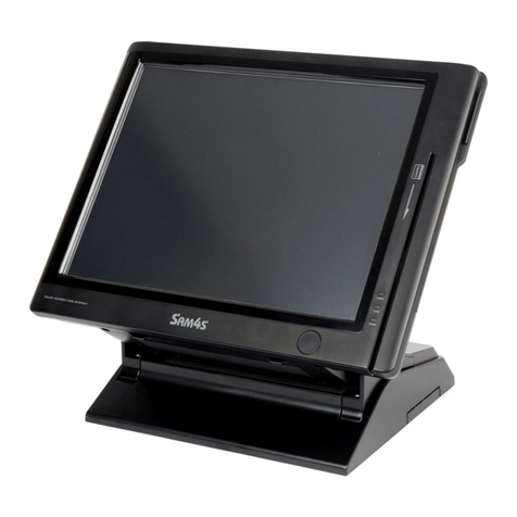
Payment Module Light
Payment Module
Scanner Module for Barcode Recognition
Printer Light
Frame Stand
Dallas or Fingerprint Module for Security
Power Light
System Power Button for On/Off
HDD Light
LAN Light
When MSR is used, the light will be lit.
It is used for the payment by MSR.
When the printer is on, the light will be lit.
When the system is on, the light will be lit.
◀ 1 - 9 ▶
HOME Contents Help Print Exit
?

04. Part Name and Function
Half-Side View
Introduction
Speaker Cover
On/Off Power Switch of Printer
Hard Disk Drive Cover
Receipt Printer Cover
Receipt Printer Feed Button for Paper
◀ 1 - 10 ▶
Introduction
Notification
Unpacking
System Features
Part Name and Function
Front View
Half-Side View
Side View
Rear View
System Installation
System Use
System Expansion
& Dismantle
Appendix A
System Set-Up
Appendix B
System Structure
▶
▶
▶
▼
SPT-7000
HOME Contents Help Print Exit
?
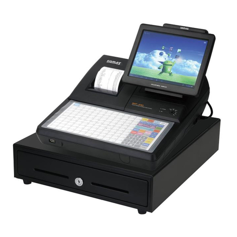
04. Part Name and Function
Side View
Introduction
Cfast Slot
USB Port
For connecting USB Interface such as
USB Keyboard, Mouse etc.
USB Port
For connecting USB Interface such as
USB Keyboard, Mouse etc.
Can use Cfast Memory
◀ 1 - 11 ▶
Introduction
Notification
Unpacking
System Features
Part Name and Function
Front View
Half-Side View
Side View
Rear View
System Installation
System Use
System Expansion
& Dismantle
Appendix A
System Set-Up
Appendix B
System Structure
▶
▶
▶
▼
SPT-7000
HOME Contents Help Print Exit
?
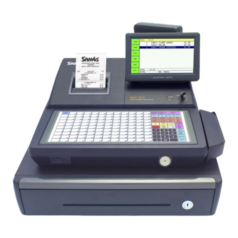
04. Part Name and Function
Rear View
Introduction
All-in-one Customer Display Cover
Interface Cover
Rear Cover
For protecting Motherboard
(When the motherboard is taken out, remove this cover.)
Cover for protecting I/O connector and AC Power Plug
(In case of connecting peripherals, dismantle the cover.)
Remove this cover and you can install customer display
(CDP Dual LCD / Dual LCD).
◀ 1 - 12 ▶
Introduction
Notification
Unpacking
System Features
Part Name and Function
Front View
Half-Side View
Side View
Rear View
System Installation
System Use
System Expansion
& Dismantle
Appendix A
System Set-Up
Appendix B
System Structure
▶
▶
▶
▼
SPT-7000
HOME Contents Help Print Exit
?
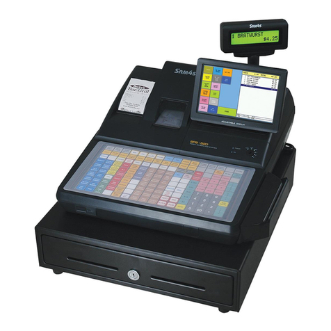
04. Part Name and Function
Rear View
Introduction
Line In / Line Out / MIC Port
DC Power-Out Port (12V)
For connecting DC power cable to the system
DSUB 9 pin / RJ45 Serial Port
For connecting serial interface such as
barcode scanner, printer, etc.
Dual Monitor Port
For connecting external monitor
USB Port
For connecting USB interfaces such as
USB signature device, keyboard, mouse, etc.
For connecting external speaker
DVR Card Port (Option)
For connecting DVR card integrating camera
(Max. 4 channels)
Parallel Port
For connecting parallel interface such as printer
RJ11 Cash Drawer Port
For connecting cash drawer
RJ45 LAN Port
For connecting RJ45 cable to use
10/100/1,000 Mbps Ethernet
◀ 1 - 13 ▶
Introduction
Notification
Unpacking
System Features
Part Name and Function
Front View
Half-Side View
Side View
Rear View
System Installation
System Use
System Expansion
& Dismantle
Appendix A
System Set-Up
Appendix B
System Structure
▶
▶
▶
▼
SPT-7000
HOME Contents Help Print Exit
?

HOME Contents Help Print Exit
?
01. Make sure of installation area
System Installation
◀ 2 - 1 ▶
Introduction
System Installation
Make sure of
installation area
Before connecting
peripherals
Connecting Peripherals
System On / Off
System Use
System Expansion
& Dismantle
Appendix A
System Set-Up
Appendix B
System Structure
▶
▶
▶
▼
SPT-7000
Choose a big and solid desk or table to support the weight of this system.
La
y this system on a stable and flat surface. Do not install on surface of carpet which may cause static electricity. The data of system may be erased or the circuit board may get damaged.
Secure the enough space surrounding this system to make air ventilation.
Keep this system away from humidity, dust, direct sunlight and high temperature. Always keep it in a cool area.
Make sure the power voltage is within safety range and being adjusted properly to the value of 100-240V before connecting the equipment to the power outlet.
Power outlets are needed for the system, printer and other peripherals respectively.
Always keep the equipment from strong magnetic or electrical objects.
▶ Risk of explosion if battery is replaced by an incorrect type.
Use the same one with the battery in the mainboard.
▶ Dispose of used batteries according to the instructions.
Caution!
!
50。
90。
5。
<STANDARD ANGLE>
You can adjust the angle depending on your using environment.
The possible range of angle is like below picture.
Note!
It is important to be sure the installed place is safe and comportable like following contents before setup the system.

02. Before connecting peripherals
System Installation
◀ 2 - 2 ▶
Pushing the both lock buttons, pull the Interface Cover and remove it.
▶ Connect peripherals after turning the power off.
▶ Please use gloves to prevent injury from the edge
of the equipment.
Caution!
!
Connecting Peripherals
Remove Interface Cover
First remove Interface Cover at the rear of the system.
HOME Contents Help Print Exit
?
Introduction
System Installation
Make sure of
installation area
Before connecting
peripherals
Connecting Peripherals
System On / Off
System Use
System Expansion
& Dismantle
Appendix A
System Set-Up
Appendix B
System Structure
▶
▶
▶
▼
SPT-7000

03. Connecting Peripherals
System Installation
◀ 2 - 3 ▶
Connect barcode scanner, serial interface devices, etc. to the serial port. Each serial device has different power specification.
After checking power spec., refer to the below table.
Use RJ-11 port when cash drawer is used.
Please set up the power after checking power spec. of cash drawer and then referring to the system composition on appendix B.
Connecting Serial Port Devices such as Barcode Scanner
Connecting RJ-11 Cash Drawer
Port
COM1
COM2
COM3
COM4
5V
Yes
Yes
Yes
Yes
12V
Yes
Yes
Yes
Yes
RI
Yes
Yes
Yes
Yes
We recommend you to use Sam4s Cash Drawer because of
different cable specifications by each manufacturer.
Note!
<Barcode Scanner>
<Cash Drawer>
HOME Contents Help Print Exit
?
Introduction
System Installation
Make sure of
installation area
Before connecting
peripherals
Connecting Peripherals
Connecting Serial Port Devices
such as Barcode Scanner
Connecting RJ-11 Cash Drawer
Connecting RJ-45 LAN Cable
Connecting USB Device
Connecting PS Module
Connecting Security
/ Scanner Module
Connecting Receipt Printer
Receipt Printer
Dismantle the Cover
for Customer Displays
Connecting DVR Card
Connecting AC Power
Cord to the Set Plug
Cable Management
System On / Off
System Use
System Expansion
& Dismantle
Appendix A
System Set-Up
Appendix B
System Structure
▶
▶
▶
▼
SPT-7000

03. Connecting Peripherals
System Installation
◀ 2 - 4 ▶
RJ-45 LAN or Internet-enabled cable can be connected.
It supports 10/100/1000Mbps.
USB connector is located at the side of and the back of the system so USB
Devices can be connected at the both locations.
USB hub can be used to connect various USB devices.
USB devices are like keyboard, mouse, CCD camera, printer and signature pad.
(According to the type of USB devices, the drivers may be required.)
Connecting RJ-45 LAN Cable
Connecting USB Device
<Mouse>
<Keyboard> <CCD Camera>
<LAN Hub>
Introduction
System Installation
Make sure of
installation area
Before connecting
peripherals
Connecting Peripherals
Connecting Serial Port Devices
such as Barcode Scanner
Connecting RJ-11 Cash Drawer
Connecting RJ-45 LAN Cable
Connecting USB Device
Connecting PS Module
Connecting Security
/ Scanner Module
Connecting Receipt Printer
Receipt Printer
Dismantle the Cover
for Customer Displays
Connecting DVR Card
Connecting AC Power
Cord to the Set Plug
Cable Management
System On / Off
System Use
System Expansion
& Dismantle
Appendix A
System Set-Up
Appendix B
System Structure
▶
▶
▶
▼
SPT-7000
HOME Contents Help Print Exit
?
Table of contents
Other Sam4s Touch Terminal manuals

Sam4s
Sam4s SPS-1000 Owner's manual

Sam4s
Sam4s SPS-500 User manual

Sam4s
Sam4s SPT-3000 Guide

Sam4s
Sam4s SAM4POS User manual

Sam4s
Sam4s SAM4POS User manual

Sam4s
Sam4s Titan-560 User manual

Sam4s
Sam4s SAP-6600 User manual

Sam4s
Sam4s Touch Screen Terminal User manual

Sam4s
Sam4s SPS-500 User manual

Sam4s
Sam4s SAP-6600II User manual