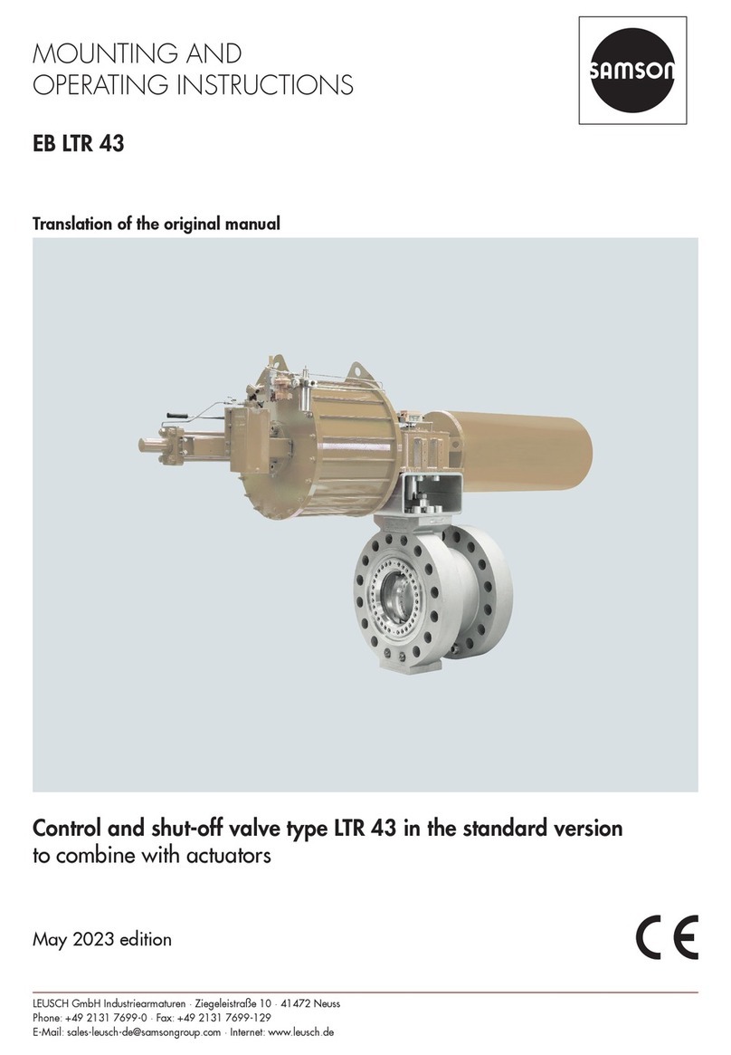
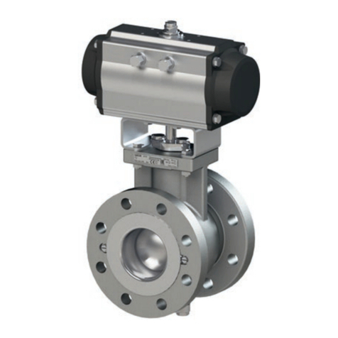
Samson EB 20b Service manual

PFEIFFER Chemie-Armaturenbau GmbH · Hooghe Weg 41 · 47906 Kempen · Germany
Phone: +49 2152 2005-0 · Fax: +49 2152 1580
sales-pfeiffer-de@samsongroup.com · www.pfeiffer-armaturen.com
MOUNTING AND
OPERATING INSTRUCTIONS
EB 20b
Translation of the original manual
Ball valve BR 20b DIN and ANSI version
to combine with actuators
February 2022 edition

EB 20b_EN
February 2022 edition
Subject to technical changes
Note regarding this installation and operating manual
This Installation and Operating Manual (EB) provides guidance
for safe assembly and operation.
The notes and instructions in this EB are binding when handling
PFEIFFER devices. The figures and illustrations in this EB are ex-
amples and must therefore be considered as such.
ÖFor safe and correct use, read this EB carefully prior to use
and keep it for later reference.
ÖIn the case of questions that go beyond the scope of this EB,
please contact the After Sales Service at PFEIFFERChemie-
ArmaturenbauGmbH.
ÖThis manual only applies to the ball valve itself, the respective
additional manual applies for the mounted actuator.
Definition of signal words
Hazardous situations that lead to death or serious injuries
Situations that can lead to death or serious injuries
Property damage and malfunctions
Additional information
Recommended action
DANGER
WARNING
NOTE
Info
Tip

EB 20b_EN
February 2022 edition
Subject to technical changes
Content
Content
1 Safety instructions and safety measures 1-1
1.1 Notes regarding possible severe personnel injury 1-2
1.2 Notes regarding possible personnel injury 1-2
1.3 Notes regarding possible property damage 1-3
1.4 Warning notes on the device 1-4
2 Markings on the device 2-1
2.1 Type plates 2-2
2.1.1 Ball valve type plates 2-2
2.1.2 Actuator type plate 2-2
2.2 Material marking 2-2
3 Design and principle of operation 3-1
3.1 Variants 3-1
3.2 Additional fittings 3-1
3.3 Attachments 3-1
3.4 Technical data 3-2
3.5 Ball valve assembly 3-2
3.5.1 Assembly of the DIN ball valve, DN15 3-2
3.5.2 Assembly of the DIN ball valve, DN25 ... 100 3-4
3.5.3 Assembly of the DIN ball valve, DN150 ... 200 3-5
3.5.4 Assembly of the ANSI ball valve 3-7
4 Shipment and on-site transport 4-1
4.1 Accepting delivery 4-1
4.2 Unpacking the ball valve 4-1
4.3 Transporting and lifting the ball valve 4-1
4.3.1 Transporting 4-1
4.3.2 Lifting 4-1
4.3.3 Lifting points on the body 4-2
4.3.4 Lifting points on the bracket 4-2
4.4 Storing the ball valve 4-3
5 Installation 5-1
5.1 Installation conditions 5-1
5.2 Preparing for assembly 5-1
5.3 Assembling the ball valve and actuator 5-1
5.4 Installing the ball valve in the pipe 5-2
5.4.1 General 5-2
5.4.2 Installing the ball valve 5-3
5.4.3 Installation instructions for lined gate ball valves with heat pack 5-3
5.5 Checking the assembled ball valve 5-3
5.5.1 Functional test 5-3
5.5.2 Pressure test of the pipe section 5-4
5.5.3 Swivelling movement 5-4
5.5.4 Fail-safe position 5-4

EB 20b_EN
February 2022 edition
Subject to technical changes
Content
6 Start-up 6-1
7 Operation 7-1
8 Malfunction 8-1
8.1 Detecting and rectifying errors 8-1
8.2 Carrying out emergency measures 8-2
9 Servicing 9-1
9.1 Periodic tests 9-1
9.2 Maintenance work 9-2
9.2.1 Replacing the seal rings and ball 9-2
9.3 Ordering spare parts and consumables 9-2
10 Decommissioning 10-1
11 Removal 11-1
11.1 Removing the ball valve from the pipe 11-1
11.2 Disassembling the actuator 11-1
12 Repairs 12-1
12.1 Replacing the V-ring packing in the case of a DIN ball valve, DN15 ... 100 12-1
12.2 Replacing the V-ring packing in the case of a DIN ball valve, DN150 ... 200 12-1
12.3 Replacing the V-ring packing in the case of a ANSI ball valve 12-1
12.4 Replacing the seal ring of the ball 12-1
12.5 Additional repairs 12-3
12.6 Sending devices to PFEIFFER 12-3
13 Disposal 13-1
14 Certificates 14-1
15 Annex 15-1
15.1 Tightening torques, lubricant and tools 15-1
15.1.1 Tightening torques 15-1
15.1.2 Lubricant 15-2
15.1.3 Tools 15-2
15.2 Spare parts 15-2
15.2.1 Spare parts of the ball valve in the DIN version, DN15 15-3
15.2.2 Spare parts of the ball valve in the DIN version, DN25 ... 100 15-4
15.2.3 Spare parts of the ball valve in the DIN version, DN150 ... 200 15-5
15.2.4 Spare parts of the ball valve in the ANSI version, NPS½ ... 8 15-6
15.3 Service 15-7

1-1
EB 20b_EN
February 2022 edition
Subject to technical changes
Safety instructions and safety measures
1 Safety instructions and safety measures
Intended use
The PFEIFFER ball valve BR 20b is manually operated in combi-
nation with an actuator for the regulation of the volume flow,
control and regulation of fluid, gaseous or vaporous media.
−The ball valve and its actuator are designed for precisely de-
fined conditions (e.g. operating pressure, utilised medium,
temperature).
Therefore the operator must make sure that the ball valve is
only used when the conditions of use comply with the design
criteria defined in the order, see also the pressure-tempera-
ture diagram.
If the operator would like to use the ball valve in other appli-
cations or environments, they must contact PFEIFFER.
−Manual ball valves are only intended for use, after installa-
tion in a pipe system, to cut off the media, let it flow through
or regulate it within the permitted pressure and temperature
limits.
−Automated ball valves are only intended for use, after instal-
lation in a pipe system and after connecting the drive to to
the control, to cut off the media, let it flow through or regulate
it within the permitted pressure and temperature limits.
−The data sheet contains the permissible pressure and temper-
ature range for these ball valves TB20b.
−The safety regulations that apply to the pipe system in which
the valves are installed and to the control system to which the
actuator is connected also apply to the ball valves.
This manual only provides safety instructions that are to be
observed additionally for ball valves.
There may be additional safety instructions in the manuals for
the actuator assemblies.
−It is assumed that this chapter is observed when using the
valve as intended.
Reasonably foreseeable erroneous use and unintended use
The ball valve is not suited for the following areas of use:
−Use outside of the technical data and the limits defined by the
design.
−Use outside of the limited defined by the peripheral devices
installed on the ball valve.
−Use outside any further limiting performance data on the
type plate.
Furthermore, the following activities are considered unintended
use:
−Use of third-party spare parts.
−Performance of maintenance and repair work that is not de-
scribed.
Qualification of operating personnel
The ball valve may only be disassembled, dismantled, assembled
and commissioned by qualified specialist personnel trained in
pressurised pipes who are familiar with the assembly, commis-
sioning and operation of this product.
−Specialist personnel in terms of this installation and operating
manual are persons who, on the basis of their vocational ed-
ucation, knowledge and experience and knowledge of the
relevant standards, are capable of evaluating the assigned
tasks and identifying possible hazards.
Personal protective equipment
Depending on the utilized medium, PFEIFFER recommends the
following protective equipment:
−Protective garments, protective gloves and eye protection
when using hot, cold, aggressive and/or corrosive media.
−Hearing protection when working near the valves.
−Request additional protective equipment from the plant oper-
ator.
Prohibition of modifications
Changes to the product are not permitted without consulting
PFEIFFER. Non-compliance invalidates the product guarantee.
PFEIFFER shall not be held liable for any resulting property dam-
age or personal injury.
Protective devices
In the case of a power supply failure, the automated ball valve
automatically switches to a certain fail-safe position, see Fail-safe
positions”in Chapter “3 Design and principle of operation”.
−The fail-safe position corresponds to the effective direction
and is indicated on the type plate of PFEIFFER actuators, see
the actuator documentation.
−The valve is to be included in the equipotential bonding of the
plant.
Warning of residual risks
To prevent personal injury or property damage, the operator and
operating personnel must use suitable measures to prevent the
hazards that can result from the flow medium and operating
pressure as well as the signal pressure and moving parts of the
ball valve.
−Therefore, the operator and operating personnel must ob-
serve all the hazard information, warning information and
information in this installation and operating manual.
Obligation of the operator to exercise diligence
The operator is responsible for proper operation as well as com-
pliance with the safety regulations.
−The operator is responsible for providing operating personnel
with this installation and operating manual as well as the ap-
plicable documents and to provide instructions on proper op-
eration.
−Furthermore, the operator must ensure that operating person-
nel and third parties are not endangered.
It is not the responsibility of PFEIFFER and therefore when using
the ball valve ensure that:
1-2 EB 20b_EN
February 2022 edition
Subject to technical changes
Safety instructions and safety measures
−The ball valve is only used as intended as described in this
chapter.
−An actuator unit that is subsequently installed on the ball
valve is adapted to it and the max. torque is observed, and is
correctly adjusted in the end positions, and in particular in
the opening position of the ball valve.
−The pipe system and control system are properly installed
and regularly checked. The wall thickness of the ball valve
body is measured such that an additional load of the usual
magnitude is taken into account for a pipe system installed
properly in this way.
−The valve is connected properly to these systems.
−The customary flow rates in continuous operation are not ex-
ceeded in this pipe system.
−PFEIFFER is contacted in the case of abnormal operating con-
ditions, such as vibrations, hydraulic shock, cavitation and
also large amounts of solid matter in the medium, especially
abrasive matter.
Obligation of operating personnel to exercise diligence
Operating personnel must be familiar with this installation and
operating manual and the applicable documents and comply
with the indicated hazard information, warning information and
other information. Furthermore, operating personnel must be fa-
miliar with the applicable regulations concerning occupational
safety and accident prevention and observe them.
Applicable standards and directives
−The ball valves fulfil the requirements of the European Pres-
sure Equipment Directive 2014/68/EU and the European
Machinery Directive 2006/42/EC. In the case of ball valves
provided with a CE marking, the Declaration of Conformity
provides information about the conformity assessment proce-
dure that was used. The corresponding declarations of con-
formity are available in the Annex of this EB, see chapter “14
Certificates“.
−According to an ignition hazard assessment according to
DIN EN ISO 80079-36, PFEIFFER ball valves do not have
any own potential ignition sources and therefore are not sub-
ject to Directive 2014/34/EU.
CE marking based on this standard is not permitted. The in-
clusion of valves in the equipotential bonding of a plant ap-
plies independently of the directive for all metal parts in po-
tentially explosive areas.
Ball valves with plastic lining (PFA, PTFE, EPDM, etc.) through
which chargeable media flows during operation, must be
provided with an electrostatically dissipative plastic lining
whose surface resistance does not exceed a value of 1GΩ
(109Ω) in accordance with DINENISO80079-36.
1.1 Notes regarding possible severe per-
sonnel injury
Hazards and ineffectiveness of the warranty!
In the case of non-compliance with the following hazard and
warning information, hazards may arise and the warranty pro-
vided by PFEIFFER may become invalid.
ÖObserve the following hazards and warning information.
ÖContact PFEIFFER in the case of questions.
Hazards and damage due to unsuitable ball valves!
Ball valves whose permissible pressure/temperature range
(=”rating”) is not sufficient for the operating conditions can pose
a danger to the user and cause damage to the pipe system.
ÖOnly operate ball valves whose permissible pressure/temper-
ature range (=”rating”) is sufficient for the operating condi-
tions, see the data sheet TB20b.
Risk of bursting of the pressure equipment!
Ball valves and pipes are pressure equipment. Improper opening
can cause the bursting of ball valve components.
ÖObserve the maximum permissible pressure for the ball valve
and plant.
ÖBefore working on the ball valve, depressurise the concerned
plant parts and the ball valve.
ÖBefore removing the ball valve from the pipe, completely re-
lease the pressure in the pipe so that the medium does not es-
cape uncontrolled from the line.
ÖBring the ball valve into the open position so the pressure is
released from the ball.
ÖEmpty the medium from the concerned plant parts and ball
valve. (Wear protective equipment)
1.2 Notes regarding possible personnel injury
Hazards due to incorrect ball valve use!
The incorrect use of the ball valve can represent a hazard for the
user and cause damage to the pipe system that are then no
longer the responsibility of PFEIFFER.
ÖThe lining selected for the parts of the ball valve that come in-
to contact with the media must be suitable for the utilised me-
dia, pressures and temperatures.
Danger of burning due to hot or cold components and pipes!
Depending on the utilised medium, ball valve components and
pipes can become very hot or very cold and cause burns upon
contact.
ÖBall valves must be protected against contact in the case of
operating temperatures >+50°C or <-20°C together with the
pipe connections.
DANGER
WARNING

1-3
EB 20b_EN
February 2022 edition
Subject to technical changes
Safety instructions and safety measures
Danger of crushing due to moving parts!
The ball valve contains moving parts (actuator and switching
shaft as well as the hand lever) that can lead to crushing if reach-
ing into it.
ÖDo not reach into the bracket during operation.
ÖWhen working on the ball valve, interrupt and lock pneumat-
ic energy and the control signal.
Danger of injury during the switching operation if performing
test runs on ball valves not installed in the pipe!
ÖDo not reach into the ball valve. This can result in serious in-
juries.
Danger of injury due to venting the actuator!
During operation, when regulating or opening and closing the
ball valve, the actuator can be ventilated.
ÖInstall the ball valve such that the actuator does not ventilate
at eye level.
ÖUse suitable silencers and plugs.
ÖWear eye protection when working near the valve.
Danger of injury due to preloaded springs!
Ball valves that are equipped with spring preloaded actuators
are under mechanical tension.
ÖBefore working on the actuator, release the compression from
the preloaded springs, see the corresponding actuator docu-
mentation.
Danger of injury due to residual medium in the ball valve!
When a ball valve must be removed from a pipe, medium can
escape from the pipe or the ball valve.
ÖIn the case of media that is harmful to health or hazardous,
the pipe must be completely emptied before a ball valve can
be removed.
ÖPay attention to the afterflow of residuals or residuals that re-
main in dead spots of the ball valve.
Danger of injury due to the releasing of body screw connec-
tions!
If the body screw connections must be released, medium can es-
cape from the ball valve.
ÖThe screw connections on the connection of the body parts
may only be released or loosened after the ball valve has
been removed.
ÖDuring reassembly, tighten the screws according to Table 15-
1 in Chapter “15-1-1 Tightening torques“ using a torque
wrench.
Dangers due to use as an end fitting!
During normal operation, in particular with gaseous, hot and/or
hazardous media, spraying medium
can cause hazards. It must be kept in mind that the media is usu-
ally hazardous!
ÖA blind flange must be assembled on the free connecting
pieces or the ball valve must be secured against unauthorised
actuation.
ÖIf a ball valve used as an end fitting in a pressurised line is
opened, this may only be done with extreme caution so that
the escaping medium does not cause any damage.
WARNING
Deviation of the breakaway and actuating forces due to
non-actuation of the ball valve!
Depending on the period of time of non-actuation, the breaka-
way and actuation forces can deviate considerably from the ac-
tuating power data in the data sheet.
It is recommended to actuate the ball valve at regular intervals.
ÖIn consideration of the design, actuation must take place dur-
ing the year.
ÖIndicate the duration of non-actuation when making an en-
quiry, so that this condition is taken into consideration in the
actuator design.
ÖIn the case of retrofitted actuators by the operator, the correct
actuator design as regards the duration of non-actuation is
no longer the responsibility of PFEIFFER.
1.3 Notes regarding possible property
damage
Damage to the ball valve due to contamination!
Contamination (e.g. solid particles) in the pipes can damage the
ball valve.
ÖThe plant operator is responsible for cleaning the pipes in the
plant.
ÖRinse the pipes prior to commissioning.
ÖObserve the maximum permissible pressure for the ball valve
and plant.
Damage to the ball valve due to unsuitable medium properties!
The ball valve is designed for a medium with certain properties.
Other media can damage the ball valve.
ÖUse the ball valve only in media that complies with the design
criteria.
Damage to the ball valve due to plant vibrations!
ÖIf necessary, secure hand-operated ball valves in the case of
plant vibrations with a locking device to prevent it from mov-
ing by itself.
Damage to the ball valve and leakage due to excessively high
or low tightening torques!
The ball valve components must be tightened with defined tor-
ques. Deviating torques can lead to ball valve leakage or dam-
age.
ÖExcessively tightened components are subject to increased
wear.
ÖInsufficiently tightened components can cause leakage.
ÖObserve the tightening torques, see Table 15-1 in Chapter
“15.1.1 Tightening torques”.
WARNING
NOTE

1-4 EB 20b_EN
February 2022 edition
Subject to technical changes
Safety instructions and safety measures
Damage to the ball valve due to an impermissible pressure in-
crease!
The ball valve body may contain small amounts of medium in the
closed and open position.
ÖUse a ball valve with an optional relief bore if it is possible
that the closed area of the ball filled with medium can heat
up due to external heat. This prevents an impermissible pres-
sure increase due to a change in the condition of the unit.
Damage to the ball valve due to unsuitable tools!
Unsuitable tools can damage the ball valve.
ÖSuitable tools are required to work on the ball valve, see
Chapter “15.1.3 Tools”.
Damage to the ball valve due to unsuitable lubricants!
Unsuitable lubricants can corrode and damage the surface.
ÖThe ball valve material requires suitable lubricants, see Chap-
ter “15.1.2 Lubricants”.
1.4 Warning notes on the device
Warning of moving parts
Figure|1-1: Warning of moving parts
There is a danger of crushing due to the rotary movements of the
actuator- and switching shaft when reaching into the bracket as
long as the pneumatic power is connected to the actuator.
NOTE Instructions for retightening the body screws
Figure|1-2: Instructions for retightening the body screws

2-1
EB 20b_EN
February 2022 edition
Subject to technical changes
Markings on the device
2 Markings on the device
Each ball valve usually has the following marking.
Table|2-1: Marking on the type plate and on the body of the valve
Pos. For Marking Remark
1 Manufacturer PFEIFFER Address see Chapter “15.4 Service”
2 Valve type BR (and number value) e.g. BR20b = Series20b, see the PFEIFFER catalogue
3Body material e.g. EN-JS 1049 No. of the material standard according to DINEN1563 (previous: GGG 40.3)
Lining e.g. PFA Material marking of the lining “PFA”
4 Size DN (and number value) Number value in [mm], e.g. DN 50/ number value in [inches], e.g. NPS2
5 Maximum pressure PN (and number value) Number value in [bar] at room temperature
6
Max. permissible op-
erating temperature TS (and number value) PS are TS are related values here at the max. permissible operating temperature with the
max. permissible operating overpressure, see also the Pressure-Temperature Diagram
PT20b-01 and PT20b-02
Max. permissible op-
erating pressure PS (and number value)
7 Test pressure PT (and number value) The test pressure must be observed depending on the device
8
Manufacturer number
from 2018 e.g. 381234/001/001
38 1234 /001 /001
Valve no. within the item
Item in the order
Order
Year of manufacture (38=2018, 39=2019, 30=2020,
31=2021 etc.)
Manufacturer number
2009 to 2017 e.g. 211234/001/001
21 1234 /001 /001
Valve no. within the item
Item in the order
Order
Year of manufacture (29=2009, 20=2010, 21=2011,
22=2012 etc.)
Manufacturer number
until 2008 e.g. 2071234/001/001
207 1234 /001 /001
Valve no. within the item
Item in the order
Order
Year of manufacture (205=2005, 206=2006, 207=2007
etc.)
9 Flow coefficient e.g. kvs 10 (DIN) = value, Cv (ANSI) = value (optional)
10 Characteristic curve e.g. % % = equal percentage, lin = linear (optional)
11 Test point number e.g. F123201-1 Specified by the customer
12 DataMatrix code
13 Conformity CE Conformity is certified separately by PFEIFFER
Code No. 0035 “Notified body” according to EU Directive = TÜV Rheinland Service GmbH
14 Flow direction ÎAttention: see the note in Chapter “5.4 Installing the ball valve in the pipe”
Markings on the body and the type plate must be permanent so that the valve remains identifiable.
Info

2-2 EB 20b_EN
February 2022 edition
Subject to technical changes
Markings on the device
2.1 Type plates
2.1.1 Ball valve type plates
Figure|2-1: Type plate (82150ae) for DN15 ... 25 and NPS½ ... 1
Figure|2-2: Type plate (82149ae) for DN40 ... 200 and NPS1½ ... 8
2.1.2 Actuator type plate
See the corresponding actuator documentation.
2.2 Material marking
The ball valves are marked on the body with material specifica-
tion, see “Table2-1: Marking on the type plate and on the body
of the valve”.
Further specifications can be requested from PFEIFFER.

3-1
EB 20b_EN
February 2022 edition
Subject to technical changes
Design and principle of operation
3 Design and principle of operation
Function and principle of operation
The media can flow in both directions through the BR20b ball
valve with full passage.
The ball (3) with its cylindrical passage is swivel-mounted around
the switching shaft. The ball swivel angle influences the flow
through the area freed between the body and the ball channel.
When the ball valve is open, the full cross section is freed.
The ball (3), in the PFA lined body, is sealed by replaceable seal
rings (4).
The switching shaft is sealed by PTFE V-ring packing (5). The
spring washers (8) located above the packing provide the preten-
sioning.
The switching shaft that leads outside is fit up to DN100/NPS4
with a hand lever. Optionally, a pneumatic rotary actuator or a
manual gear can be installed.
The ball valve can also be used for control purposes see the data
sheet DB20a-kd.
Fail-safe position
Depending on the mounting of the pneumatic rotary actuator, the
ball valve has two fail-safe positions that are activated when the
pressure is released as well when the supply air fails:
−Ball valve with fail-close actuator [FC]:
Upon air failure, the ball valve is closed. The ball valve opens
when the signal pressure increases, acting against the force
of the springs.
−Ball valve with fail-open actuator [FO]:
Upon air failure, the ball valve is opened. The ball valve clos-
es when the signal pressure increases, acting against the
force of the springs.
Changing the fail-safe position
The fail-safe position of the actuator can be reversed if required,
for this purpose see the installation and operating instructions for
the respective pneumatic actuator.
Operating elements and functions
The BR20b ball valve can be selected in the following versions:
−With a hand lever (DN15 up to 100 or NPS1 up to 4).
−With a manual gear.
−With PFEIFFER rotary actuator BR 31a.
−With rotary actuators from other manufacturers (for details
see the respective data sheet).
3.1 Variants
−Body made of other materials, e.g. 1.4571
Info
−Use as a control ball valve with calibrated seat ring
(≤DN100)
−PFA-conductive lining
−Stainless steel heat pack
−Various ball and seal ring materials
−FDA-compliant sealing material
−Two-part ball/switching shaft
−Customer-adapted versions
3.2 Additional fittings
Strainer
PFEIFFER recommends installing a strainer in front of the ball
valve. A strainer prevents the solid content in the medium from
damaging the ball valve.
Bypass and shut-off valve
PFEIFFER recommends installing a shut-off valve in front of the
strainer as well as behind the ball valve and to create a bypass.
By means of the bypass, the entire plant does not have to be de-
commissioned during maintenance and repair work on the ball
valve.
Insulation
The ball valves can be insulated to reduce the passage of heat
energy. If necessary, observe the notes in Chapter “5.4 Installing
the ball valve in the pipe”.
Grip protection
In the case of conditions of use that require a high level of safety
(e.g. if the ball valve is freely accessible to untrained specialist
personnel), PFEIFFER offers a safety guard to prevent the risk of
crushing due to moving parts (actuator- and switching shaft).
The risk assessment of the plant by the operator will indicate if
the installation of this protective device is required for the safe
operation of the ball valve in the plant.
3.3 Attachments
The following accessories are available for the ball valve either
individually or in combinations:
−Locking device
−Switching shaft extension (100 mm standard)
−Pneumatic or electric rotary actuator
−Positioner (with the control ball valve option)
−Limit switch
−Solenoid valves
−Filter - reducing station
−Control ball valve with calibrated seat ring
Other additional equipment is possible according to specifica-
tions on request.

3-2 EB 20b_EN
February 2022 edition
Subject to technical changes
Design and principle of operation
3.4 Technical data
The type plates of the ball valve and actuator offer information
about the valve version, see Chapter “2 Markings on the device”.
Detailed information is available in the data sheet TB20b.
3.5 Ball valve assembly
The BR20b ball valves in the “DIN” version have design differ-
ences with respect to the “ANSI” version so that they cannot be
documented in one construction manual.
−The assembly of the DIN ball valve DN15 is described in
chapter 3.5.1.
−The assembly of the DIN ball valve DN25 ... 100 is de-
scribed in chapter 3.5.2 .
−The assembly of the DIN ball valve DN150 ... 200 is de-
scribed in chapter 3.5.3 .
−Chapter 3.5.4 describes the assembly of the ANSI ball valve.
Preparation of the assembly
To assemble the ball valve, all parts must be prepared, e.g. the
parts are carefully cleaned and placed on a soft mat (rubber mat
or other).
Keep in mind that plastic parts are almost always very soft and
very delicate, and in particular the sealing surfaces may not be
damaged.
Damage to the ball valve due to unsuitable lubricants!
Unsuitable lubricants can corrode and damage the surface. The
ball valve material requires suitable lubricant. A suitable lubri-
cant must be selected for grease-free ball valves, especially for
use with oxygen.
ÖFor suitable lubricant, see Chapter “15.1.2 Lubricant”.
The position and arrangement of the individual parts shown in
the drawings must be observed during assembly.
3.5.1 Assembly of the DIN ball valve, DN|15
3.5.1.1 Assembly of the body halves
ÖPlace both body halves (1 and 2) with the flange facing
downward on an even and clean work surface, so that the
inside of the ball valve is easy to reach.
ÖInsert the seal rings (4a and 4b) in the body halves (1 and 2).
Info
NOTE
Info
The seal rings may not be installed without clearance. To achieve
the tightness of the ball valve, the seal rings must be installed in
their seat with sufficient clearance. If this is not possible, please
contact PFEIFFER.
ÖPlace the ball (3) on the seal ring of a body half (1 or 2).
ÖPlace the bearing bushing (22) and V-ring packing (5) with a
slightly rotary movement over the stem of the ball. The num-
ber of packing rings can be found on the drawing, see Fig-
ure3-1.
ÖInsert the ball stem with the V-ring packing into the packing
space in the body.
Make sure that the ball (3) and V-ring packing (5) are clearly fit-
ted in the body.
ÖPlace the second body half onto the previously described
body half, so that it centres itself on the ball stem and the
V-ring packing as well as the seal ring.
Make sure that the V-ring packing is not squashed at the side by
the body halves.
ÖFasten the body sections together with screws (10), washers
(12) and nuts (11) so they are hand-tight.
−Depending on the nominal size, stud bolts with nuts or screws
can be used.
−The final screw connection of the body halves is performed dur-
ing a subsequent assembly step.
3.5.1.2 Final assembly of the ball valve
ÖClamp the ball valve in a vice for further assembly with the
base body flange (1).
Damage to the flange due to improper handling!
ÖDo not damage the housing flange, especially the sealing
surfaces.
ÖPlace the set of spring washers (8) over the ball stem onto the
V-ring packing. The arrangement and quantity of the spring
washers can be found on the drawing, see Figure3-1.
ÖInsert the bearing bushing (7) into the stuffing box flange (6).
ÖPlace the pre-assembled stuffing box flange on the body and
adjust with screws (9).
Info
Info
Info
NOTE

3-3
EB 20b_EN
February 2022 edition
Subject to technical changes
Design and principle of operation
Figure|3-1: Sectional drawing of the ball valve in the DIN version, DN15 ... 100
Table|3-1: Parts list of the ball valve in the DIN version, DN15 ... 100
Pos. Designation Pos. Designation
1 Main body with lining 9 Screw
2 Body with lining 10 Screw / stud bolt
3 Ball with coating 11 Nut
4 Seat ring 12 Washer
5 V-ring packing 14 Bush
6 Stuffing box flange 20 Shaft
7 Bearing bush 22 Bearing bush
8 Set of spring washers

3-4 EB 20b_EN
February 2022 edition
Subject to technical changes
Design and principle of operation
ÖTighten the screws evenly in a criss-cross pattern until a gap
between 1 - 2 mm has formed between the stuffing box
flange and the body.
The final screw connection of the stuffing box is performed dur-
ing a subsequent assembly step.
ÖTighten the nuts (11) on the body sections (1 and 2).
For the tightening sequence and tightening torques of the respec-
tive nominal sizes, see Figure 15.1 and Table 15.1 in Chapter
“15.1.1 Tightening torques”.
ÖTo complete the assembly, tighten the screws (9) on the stuff-
ing box (6) evenly and in a criss-cross pattern.
Prior to the leak test, actuate the valve a few times so that the ball
can centre on the seal rings and provide an optimal seal.
3.5.2 Assembly of the DIN ball valve, DN|25
... 100
3.5.2.1 Preassembly of the ball valve
ÖPlace the base body (1) with the flange facing downward on
an even and clean work surface, so that the inside of the ball
valve is easy to reach.
ÖInsert the seal ring (4a) into the base body.
The seal rings may not be installed without clearance. To achieve
the tightness of the ball valve, the seal rings must be installed in
their seat with sufficient clearance. If this is not possible, please
contact PFEIFFER.
Preassembly of the ball valve with the one-part ball/switching
shaft
ÖInsert the ball (3) with the shaft tilted into the packing space.
The nominal size bore of the ball faces the same direction as the
base body bore while being inserted.
For further assembly, see Chapter “3.5.2.2 Final assembly of the
ball valve”.
Info
Info
Info
Info
Info
Preassembly of the ball valve with the two-part ball/switching
shaft
ÖInsert the switching shaft (20) tilted into the packing space.
ÖInsert the ball (3) such that the slit in the ball sits perfectly on
the dihedron of the switching shaft (20).
The nominal size bore of the ball is transverse to the base body
bore while being inserted.
For further assembly, see Chapter “3.5.2.2 Final assembly of the
ball valve”.
3.5.2.2 Final assembly of the ball valve
ÖPlace the body (2) with the flange facing downward on an
even and clean work surface, so that the inside of the ball
valve is easy to reach.
ÖInsert the seal ring (4b) into the body.
The seal rings may not be installed without clearance. To achieve
the tightness of the ball valve, the seal rings must be installed in
their seat with sufficient clearance. If this is not possible, please
contact PFEIFFER.
ÖPlace the body (2) with the preassembled seal ring (4b) on
the base body (1) and push together carefully.
ÖTurn the body (2) such that the bores in both body halves (1
and 2) lie above each other.
ÖPush the washer (12) over the lightly lubricated screws (10)
and adjust the body halves (1 and 2).
ÖPlace the washers (12) over the screw ends and tighten hand-
tight with nuts (11).
−Depending on the nominal size, stud bolts with nuts or screws
can be used.
−The final screw connection of the body halves is performed dur-
ing a subsequent assembly step.
ÖClamp the ball valve in a vice for further assembly with the
base body flange (1).
Damage to the flange due to improper handling!
ÖDo not damage the housing flange, especially the sealing
surfaces.
ÖCenter the ball shaft (3) in the packing area with the V-ring
packing bottom ring (5).
ÖPush the bottom ring to the oval body base.
Info
Info
Info
NOTE

3-5
EB 20b_EN
February 2022 edition
Subject to technical changes
Design and principle of operation
Push the bottom ring in with more force, therefore use a suitable
auxiliary tool for assembly.
ÖUse this auxiliary tool also to insert the V-ring packing (5)
V-ring by V-ring into the body. The arrangement and quanti-
ty of the V-rings can be found on the drawing, see Fig-
ure3-1.
ÖTighten the screws (10) and nuts (11) on the body sections (1
and 2).
For the tightening sequence and tightening torques of the respec-
tive nominal sizes, see Figure 15.1 and Table 15.1 in Chapter
“15.1.1 Tightening torques”.
ÖPlace the bushing (14) on the V-ring packing.
ÖPlace the set of spring washers (8) over the bushing (14) onto
the V-ring packing. The arrangement and quantity of the
spring washers can be found on the drawing, see Figure3-1.
ÖPush the bearing bushing (7) into the stuffing box flange (6).
ÖPlace the stuffing box flange with the bearing bushing over
the switching shaft onto the body.
ÖEvenly adjust the stuffing box flange with lightly lubricated
screws (9) and tighten in a criss-cross pattern.
Prior to the leak test, actuate the valve a few times so that the ball
can centre on the seal rings and provide an optimal seal.
3.5.3 Assembly of the DIN ball valve,
DN|150 ... 200
3.5.3.1 Assembly of the body halves
ÖPlace both body halves (1 and 2) with the flange facing
downward on an even and clean work surface, so that the
inside of the ball valve is easy to reach.
ÖDrive the pin (21) into the base body (1).
ÖInsert the seal rings (4a and 4b) in the body halves (1 and 2).
The seal rings may not be installed without clearance. To achieve
the tightness of the ball valve, the seal rings must be installed in
their seat with sufficient clearance. If this is not possible, please
contact PFEIFFER.
Info
Info
Info
Info
ÖPlace the V-ring packing (5) in the PTFE bushing (17). The ar-
rangement and quantity of the V-rings can be found on the
drawing, see Figure3-2.
ÖPush the bushing (15) carefully over the packing (7) and the
PTFE bushing (17).
When this packing unit is preassembled, the bottom ring of the
packing (7) protrudes past the bushing (15).
Preassembly of the ball valve with the one-part ball/switching
shaft
ÖPlace the ball (3) on the seal ring of a body half (1 or 2).
ÖPlace the preassembled packing unit with a slightly rotary
movement over the stem of the ball.
ÖInsert the ball stem with the packing unit into the packing
space in the body.
Make sure that the ball (3) and packing unit are clearly fitted in
the body.
For further assembly, see Chapter “3.5.3.2 Final assembly of the
ball valve”.
Preassembly of the ball valve with the two-part ball/switching
shaft
ÖPlace the preassembled packing unit with a slightly rotary
movement over the switching shaft (20).
ÖInsert the switching shaft with the packing unit into the pack-
ing space of a body half (1 or 2).
ÖInsert the ball (3) on the seal ring such that the slit in the ball
sits perfectly on the dihedron of the switching shaft (20).
Make sure that the ball (3) with switching shaft (20) and packing
unit are clearly fitted in the body.
For further assembly, see Chapter “3.5.3.2 Final assembly of the
ball valve”.
3.5.3.2 Final assembly of the ball valve
ÖPlace the second body half onto the previously described
body half, so that it centres itself on the ball stem and the
V-ring packing as well as the seal ring.
Make sure that the V-ring packing is not squashed at the side by
the body halves.
ÖFasten the body halves together with screws (10), washers
(12) and nuts (11) so they are hand-tight.
−Depending on the nominal size, stud bolts with nuts or screws
can be used.
−The final screw connection of the body halves is performed dur-
ing a subsequent assembly step.
Info
Info

3-6 EB 20b_EN
February 2022 edition
Subject to technical changes
Design and principle of operation
Figure|3-2: Sectional drawing of the ball valve in the DIN version, DN150 ... 200
Table|3-2: Parts list of the ball valve in the DIN version, DN150 ... 200
Pos. Designation Pos. Designation
1 Body with lining 10 Screw / stud bolt
2 Body with lining 11 Nut
3 Ball with coating 12 Washer
4 Seat ring 15 Bush
5 V-ring packing 16 Spring washer
6 Stuffing box flange 17 Bush
7 Bearing bush 18 Center ring
8 Set of spring washers 20 Shaft
9 Screw 21 Pin

3-7
EB 20b_EN
February 2022 edition
Subject to technical changes
Design and principle of operation
ÖFasten the body halves together with screws (10), washers
(12) and nuts (11) so they are hand-tight.
−Depending on the nominal size, stud bolts with nuts or screws
can be used.
−The final screw connection of the body halves is performed dur-
ing a subsequent assembly step.
ÖClamp the ball valve in a vice for further assembly with the
base body flange (1).
Damage to the flange due to improper handling!
ÖDo not damage the housing flange, especially the sealing
surfaces.
ÖPlace the spring washer(s) (16) on the bushing (15). The lo-
cation and quantity of the spring washer(s) can be found on
the drawing, see Figure3-2.
ÖPlace the centring ring (18) on the spring washer(s) (16).
ÖInsert the set of spring washers (8) in the centring ring until
reaching the bottom ring of the V-ring packing. The arrange-
ment and quantity of the spring washers can be found on the
drawing, see Figure3-2.
ÖInsert the bearing bushing (7) into the stuffing box flange (6).
ÖPlace the pre-assembled stuffing box flange on the body and
adjust with screws (9).
ÖTighten the screws evenly in a criss-cross pattern until a gap
between 1 - 2 mm has formed between the stuffing box
flange and the body.
The final screw connection of the stuffing box is performed dur-
ing a subsequent assembly step
ÖTighten the screws (10) and nuts (11) on the body halves (1
and 2).
For the tightening sequence and tightening torques of the respec-
tive nominal sizes, see Figure 15.1 and Table 15.1 in Chapter
“15.1.1 Tightening torques”.
ÖTo complete the assembly, tighten the screws (9) on the stuff-
ing box (6) evenly and in a criss-cross pattern.
Prior to the leak test, actuate the valve a few times so that the ball
can centre on the seal rings and provide an optimal seal.
Info
NOTE
Info
Info
Info
3.5.4 Assembly of the ANSI ball valve
3.5.4.1 Assembly of the body halves
ÖPlace both body halves (1 and 2) with the flange facing
downward on an even and clean work surface, so that the
inside of the ball valve is easy to reach.
ÖDrive the pin (21) in the case of NPS6 and NPS8 into the
base body (1).
ÖInsert the seal rings (4a and 4b) in the body halves (1 and 2).
The seal rings may not be installed without clearance. To achieve
the tightness of the ball valve, the seal rings must be installed in
their seat with sufficient clearance. If this is not possible, please
contact PFEIFFER.
ÖPlace the V-ring packing (5) in the PTFE bushing (17). The ar-
rangement and quantity of the V-rings can be found on the
drawing, see Figure3-3.
ÖPush the bushing (15) carefully over the packing (7) and the
PTFE bushing (17).
When this packing unit is preassembled, the bottom ring of the
packing (7) protrudes past the bushing (15).
Preassembly of the ball valve with the one-part ball/switching
shaft
ÖPlace the ball (3) on the seal ring of a body half (1 or 2).
ÖPlace the preassembled packing unit with a slightly rotary
movement over the stem of the ball.
ÖInsert the ball stem with the V-ring packing into the packing
space in the body.
Make sure that the ball (3) and V-ring packing (5) are clearly fit-
ted in the body.
For further assembly, see Chapter “3.5.4.2 Final assembly of the
ball valve”.
Preassembly of the ball valve with the two-part ball/switching
shaft
ÖPlace the preassembled packing unit with a slightly rotary
movement over the switching shaft (20).
ÖInsert the switching shaft with the V-ring packing into the
packing space of a body half (1 or 2).
ÖInsert the ball (3) on the seal ring such that the slit in the ball
sits perfectly on the dihedron of the switching shaft (20).
Make sure that the ball (3) with switching shaft (20) and V-ring
packing (5) are clearly fitted in the body.
For further assembly, see Chapter “3.5.4.2 Final assembly of the
ball valve”.
Info

3-8 EB 20b_EN
February 2022 edition
Subject to technical changes
Design and principle of operation
Figure|3-3: Sectional drawing of the ball valve in the ANSI version
Table|3-3: Parts list of the ball valve in the ANSI version
Pos. Designation Pos. Designation
1 Main body with lining 10 Screw / stud bolt
2 Body with lining 11 Nut
3 Ball with coating 12 Washer
4 Seat ring 15 Bush
5 V-ring packing 16 Spring washer
6 Stuffing box flange 17 Bush
7 Bearing bush 18 Center ring
8 Set of spring washers 20 Shaft
9 Screw 21 Pin

3-9
EB 20b_EN
February 2022 edition
Subject to technical changes
Design and principle of operation
3.5.4.2 Final assembly of the ball valve
ÖPlace the second body half onto the previously described
body half, so that it centres itself on the ball stem and the
V-ring packing as well as the seal ring.
Make sure that the V-ring packing is not squashed at the side by
the body halves.
ÖFasten the body halves together with screws (10), washers
(12) and nuts (11) so they are hand-tight.
−Depending on the nominal size, stud bolts with nuts or screws
can be used.
−The final screw connection of the body halves is performed dur-
ing a subsequent assembly step.
ÖClamp the ball valve in a vice for further assembly with the
base body flange (1).
Damage to the flange due to improper handling!
ÖDo not damage the housing flange, especially the sealing
surfaces.
ÖPlace the spring washer(s) (16) on the bushing (15). The lo-
cation and quantity of the spring washer(s) can be found on
the drawing, see Figure3-3.
ÖPlace the centring ring (18) on the spring washer(s) (16).
ÖInsert the set of spring washers (8) in the centring ring until
reaching the bottom ring of the V-ring packing. The arrange-
ment and quantity of the spring washers can be found on the
drawing, see Figure3-3.
ÖInsert the bearing bushing (7) into the stuffing box flange (6).
ÖPlace the pre-assembled stuffing box flange on the body and
adjust with screws (9).
ÖTighten the screws evenly in a criss-cross pattern until a gap
between 1 - 2 mm has formed between the stuffing box
flange and the body.
The final screw connection of the stuffing box is performed dur-
ing a subsequent assembly step
Info
Info
NOTE
Info
ÖTighten the screws (10) and nuts (11) on the body halves (1
and 2).
For the tightening sequence and tightening torques of the respec-
tive nominal sizes, see Figure 15.1 and Table 15.1 in Chapter
“15.1.1 Tightening torques”.
ÖTo complete the assembly, tighten the screws (9) on the stuff-
ing box (6) evenly and in a criss-cross pattern.
Prior to the leak test, actuate the valve a few times so that the ball
can centre on the seal rings and provide an optimal seal.
Info
Info

3-10 EB 20b_EN
February 2022 edition
Subject to technical changes
Design and principle of operation
Table of contents
Other Samson Control Unit manuals

Samson
Samson BR 26l User manual

Samson
Samson 42-10 RS Service manual

Samson
Samson Valve Series Service manual

Samson
Samson 3354 Service manual

Samson
Samson TROVIS 5100 Service manual

Samson
Samson 3244 Service manual

Samson
Samson 3251 Service manual

Samson
Samson 2488 N Service manual

Samson
Samson 2357-1 Service manual

Samson
Samson 3964 Service manual

Samson
Samson 3349 Service manual

Samson
Samson EB 20a Service manual

Samson
Samson EB 3963 EN Service manual

Samson
Samson 3259 Setup guide

Samson
Samson 3351 Service manual

Samson
Samson EB 8139 EN Service manual

Samson
Samson 3271 Service manual

Samson
Samson 42-36 E Service manual

Samson
Samson 2422 series Service manual

Samson
Samson 3711 Service manual