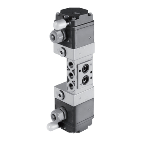
Samson 3969 Service manual

Translation of original instructions
EB 3969 EN
Edition June 2018
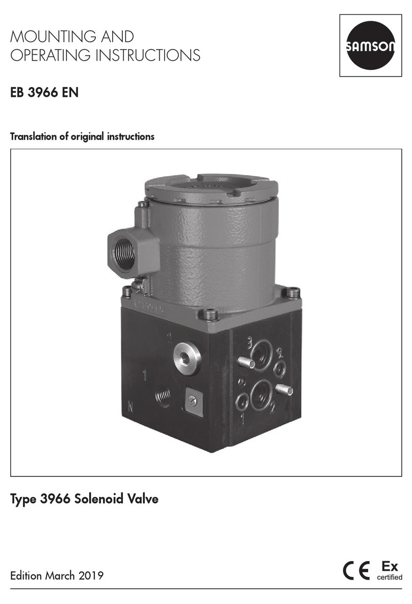
Type3969 Solenoid Valve

Note on these mounting and operating instructions
These mounting and operating instructions assist you in mounting and operating the device
safely. The instructions are binding for handling SAMSON devices.
ÎFor the safe and proper use of these instructions, read them carefully and keep them for
later reference.
ÎIf you have any questions about these instructions, contact SAMSON‘s After-sales Service
Department (aftersalesser[email protected]).
The mounting and operating instructions for the devices are included in
the scope of delivery. The latest documentation is available on our website
at www.samson.de > Service & Support > Downloads > Documentation.
Denition of signal words
Hazardous situations which, if not avoided,
will result in death or serious injury
Hazardous situations which, if not avoided,
could result in death or serious injury
Property damage message or malfunction
Additional information
Recommended action
DANGER
!
WARNING
!
NOTICE
!
Note
Tip
2 EB 3969 EN

Contents
EB 3969 EN 3
1 Safety instructions and measures ...................................................................5
1.1 Notes on possible severe personal injury .........................................................8
1.2 Notes on possible personal injury ...................................................................8
1.3 Notes on possible property damage................................................................9
2 Markings on the device ...............................................................................10
2.1 Nameplate..................................................................................................10
2.2 Article code.................................................................................................11
2.3 Summary of explosion protection approvals...................................................13
3 Design and principle of operation ................................................................14
3.1 Accessories and spare parts .........................................................................15
3.2 Technical data .............................................................................................18
3.3 Dimensions in mm........................................................................................22
4 Measures for preparation............................................................................27
4.1 Unpacking ..................................................................................................27
4.2 Transporting ................................................................................................27
4.3 Storage.......................................................................................................27
5 Mounting and start-up.................................................................................28
5.1 Installation...................................................................................................28
5.1.1 DirectattachmentaccordingtoVDI/VDE3847 ..............................................29
5.1.2 RotaryactuatorsaccordingtoVDI/VDE3845................................................30
5.1.3 AttachmentaccordingtoIEC60534-6...........................................................31
5.2 Exhaust air feedback for single-acting actuators.............................................32
5.2.1 DirectattachmentaccordingtoVDI/VDE3847 ..............................................32
5.2.2 RotaryactuatorsaccordingtoVDI/VDE3845................................................32
5.2.3 AttachmentaccordingtoIEC60534-6...........................................................32
5.3 Pneumatic connections..................................................................................32
5.3.1 Connecting the supply air.............................................................................32
5.3.2 Port labeling................................................................................................33
5.3.3 Sizing of the connecting line .........................................................................33
5.3.4 Compressed air quality.................................................................................34
5.3.5 Pilot supply..................................................................................................34
Contents
4 EB 3969 EN
5.4 Electrical connections ...................................................................................36
5.4.1 Cable entry with cable gland........................................................................36
5.4.2 Connecting the power supply........................................................................37
6 Operation...................................................................................................38
7 Servicing.....................................................................................................38
7.1 Preparation for return shipment.....................................................................38
8 Malfunctions ...............................................................................................39
8.1 Troubleshooting ...........................................................................................39
8.2 Emergency action ........................................................................................39
9 Decommissioning and removal ....................................................................40
9.1 Decommissioning.........................................................................................40
9.2 Removing the solenoid valve.........................................................................40
9.3 Disposal......................................................................................................40
10 Appendix....................................................................................................41
10.1 After-sales service........................................................................................41

EB 3969 EN 5
Safety instructions and measures
1 Safety instructions and measures
Intended use
TheType3969SolenoidValveismountedontopneumaticlinearorrotaryactuatorstocon-
trol them. Upon failure of the air supply, the solenoid valve vents the actuator, causing the
valve to move to the fail-safe position determined by the actuator. The device is designed to
operateunderexactlydenedconditions(e.g.operatingpressure,temperature).Therefore,
operators must ensure that the solenoid valve is only used in applications where the operat-
ing conditions correspond to the technical data. In case operators intend to use the solenoid
valveinotherapplicationsorconditionsthanspecied,contactSAMSON.
SAMSON does not assume any liability for damage resulting from the failure to use the de-
vice for its intended purpose or for damage caused by external forces or any other external
factors.
ÎRefertothetechnicaldataforlimitsandeldsofapplicationaswellaspossibleuses.
Reasonably foreseeable misuse
The solenoid valve is not suitable for the following applications:
−Useoutsidethelimitsdenedduringsizingandbythetechnicaldata
Furthermore, the following activities do not comply with the intended use:
−Use of non-original spare parts
−Performingmaintenanceactivitiesnotspecied
Qualications of operating personnel
Thesolenoidvalvemustbemounted,startedupandservicedbyfullytrainedandqualied
personnel only; the accepted industry codes and practices are to be observed. According to
these mounting and operating instructions, trained personnel refers to individuals who are
able to judge the work they are assigned to and recognize possible hazards due to their spe-
cialized training, their knowledge and experience as well as their knowledge of the applica-
ble standards.
Explosion-protected versions of this device must be operated only by personnel who has un-
dergone special training or instructions or who is authorized to work on explosion-protected
devices in hazardous areas.

6 EB 3969 EN
Safety instructions and measures
Personal protective equipment
No personal protective equipment is required for the direct handling of the solenoid valve.
Work on the control valve may be necessary when mounting or removing the device.
ÎObservetherequirementsforpersonalprotectiveequipmentspeciedinthevalvedocu-
mentation.
ÎCheck with the plant operator for details on further protective equipment.
Revisions and other modications
Revisions,conversionsorothermodicationsoftheproductarenotauthorizedbySAMSON.
They are performed at the user's own risk and may lead to safety hazards, for example. Fur-
thermore, the product may no longer meet the requirements for its intended use.
Warning against residual hazards
The solenoid valve has a direct effect on the control valve. To avoid personal injury or prop-
erty damage, plant operators and operating personnel must prevent hazards that could be
caused in the control valve by the process medium, the operating pressure, the signal pres-
sure or by moving parts by taking appropriate precautions. They must observe all hazard
statements, warning and caution notes in these mounting and operating instructions, espe-
cially for installation, start-up and service work.
If inadmissible motions or forces are produced in the pneumatic actuator as a result of the
supply pressure, it must be restricted using a suitable supply pressure reducing station.
Responsibilities of the operator
The operator is responsible for proper operation and compliance with the safety regulations.
Operators are obliged to provide these mounting and operating instructions to the operating
personnel and to instruct them in proper operation. Furthermore, the operator must ensure
that operating personnel or third persons are not exposed to any danger.
Responsibilities of operating personnel
Operating personnel must read and understand these mounting and operating instructions as
wellasthespeciedhazardstatements,warningandcautionnotes.Furthermore,theoperat-
ing personnel must be familiar with the applicable health, safety and accident prevention
regulations and comply with them.

EB 3969 EN 7
Safety instructions and measures
Servicing explosion-protected devices
If a part of the device on which the explosion protection is based needs to be serviced, the
devicemustnotbeputbackintooperationuntilaqualiedinspectorhasassesseditaccord-
ingtoexplosionprotectionrequirements,hasissuedaninspectioncerticate,orgiventhe
deviceamarkofconformity.Inspectionbyaqualiedinspectorisnotrequiredifthemanu-
facturer performs a routine test on the device before putting it back into operation. Document
the passing of the routine test by attaching a mark of conformity to the device. Replace ex-
plosion-protected components only with original, routine-tested components by the manufac-
turer.
Devices that have already been operated outside hazardous areas and are intended for fu-
ture use inside hazardous areas must comply with the safety requirements placed on serviced
devices. Before being operated inside hazardous areas, test the devices according to the
specicationsforservicingexplosion-protecteddevices.
Maintenance, calibration and work on equipment
ÎOnly use intrinsically safe current/voltage calibrators and measuring instruments for in-
terconnection with intrinsically safe circuits to check or calibrate the equipment inside or
outside hazardous areas.
ÎObservethemaximumpermissiblevaluesspeciedintheappendixofthisdocumentfor
the intrinsically safe circuit.
Referenced standards and regulations
DeviceswithaCEmarkingfullltherequirementsoftheDirectives2014/30/EUand
2014/34/EU. This EU declaration of conformity is included in the appendix of this docu-
ment.
Referenced documentation
The following documents apply in addition to these mounting and operating instructions:
−The mounting and operating instructions of the components on which the solenoid valve
is mounted (valve, actuator, valve accessories etc.)
−Safety manual of the solenoid valve uSH3969
−Safety manual of the restrictor plates uSH3967-2

8 EB 3969 EN
Safety instructions and measures
1.1 Notes on possible severe personal injury
DANGER
!
Risk of fatal injury due to the formation of an explosive atmosphere.
Incorrect installation, operation or maintenance of the solenoid valve in potentially ex-
plosive atmospheres may lead to ignition of the atmosphere and cause death.
ÎFor mounting and electrical installation in hazardous areas, observe the explosion
protection approvals as well as the relevant electrotechnical regulations and the ac-
cident prevention regulations that apply in the country of use.
ÎEN60079-14appliesinEurope:Electricalinstallationsdesign,selectionanderec-
tion
ÎObservethetypeofprotectionandthespecicconditionsforthetypeofprotection
according to the instructions for explosion protection in the appendix of this docu-
ment.
Risk of fatal injury as a result of electrostatic discharge at the device.
ÎInhazardousareas(withtypeofprotectionExt),mountthedeviceinsuchawaythat
electrostatic charging cannot take place.
1.2 Notes on possible personal injury
WARNING
!
Incorrect electrical connection will render the explosion protection unsafe.
ÎAdhere to the terminal assignment and observe correct polarity.
ÎDo not undo the enameled screws.
ÎDonotexceedthemaximumpermissiblevalues(Ui,li,Pi,Ci,Li)speciedintheEC
typeexaminationcerticateswheninterconnectingintrinsicallysafeelectricalequip-
ment.
Risk of personal injury due to moving parts on the valve.
During operation and when the solenoid valve is triggered, the actuator stem moves
throughitsentiretravelrange.Injurytohandsorngersispossibleiftheyareinserted
into the valve.
ÎWhilethevalvemoves,donotinserthandsorngersintothevalveyokeanddonot
touch any moving valve parts.

EB 3969 EN 9
Safety instructions and measures
1.3 Notes on possible property damage
NOTICE
!
Risk of damage to the solenoid valve due to incorrect mounting position.
ÎDo not seal the vent opening when the device is installed on site.
Risk of damage to the solenoid valve due to impermissible pressures.
ÎDo not connect a supply pressure to the solenoid valve that exceeds the maximum
supply pressure.
Incorrect assignment of the terminals will damage the solenoid valve and will lead to
malfunction.
For the solenoid valve to function properly, the prescribed terminal assignment must be
observed.
ÎConnect the electrical wiring to the solenoid valve according to the prescribed termi-
nal assignment.

10 EB 3969 EN
Markings on the device
2 Markings on the device
2.1 Nameplate
1 Article code
2CongurationID
3 Serial number
4 Order number
5 Device index
6Safety approval
1
2
3
4
56
Version without explosion protection
1
2
3
456
Version with explosion protection

EB 3969 EN 11
Markings on the device
2.2 Article code
Solenoid valve Type3969- x x x x x x x x x x x x x x x x x x x x x x x
Type of protection
Without explosion protection 0 0 0
ATEX II2GExiaIICT4/T6Gb
II 2D Ex ia IIIC T85 °C Db 110
IECEx ExiaIICT4/T6Gb
Ex ia IIIC T85°C Db 111
ATEX
II3GExecIICT4/T6Gcor
II3GExnAIICT4/T6
II 2 D Ex tb IIIC T85°C Db 810
IECEx Exec(ornA)IICT4/T6Gc
Ex tb IIIC T85°C Db 811
Nominal signal
14.7to24VDC 3
Manual override
Without 0
Pushbutton underneath the enclosure cover 1
Switching function
3/2-way function with spring-return mechanism 0 0
Mounting
NAMURinterface¼accordingtoVDI/VDE3845forrotary
actuators 0
NAMURribaccordingtoIEC60534-6forlinearactuators/
threaded connection 2
Direct attachment to mounting block with positioner according to
VDI/VDE3847 3
NAMURinterface½accordingtoVDI/VDE3845forrotary
actuators 4
NAMURinterface¼accordingtoVDI/VDE3845forrotary
actuators with adapter plate for external air connections 5
1) Theairowratewhenp1=2.4barandp2=1.0bariscalculatedusingthefollowingformula:
Q = KVSx36.22inm³/h.

12 EB 3969 EN
Markings on the device
Solenoid valve Type3969- x x x x x x x x x x x x x x x x x x x x x x x
KVS1)
0.3 0
2.0 2
4.3 4
Material
Aluminum 1
Pneumatic connection
G¼ 1
¼NPT 2
G½ 3
½NPT 4
Pilot valve connection
Without (ports sealed by two blanking plugs) 0
1 (with internal pilot supply) 1
2 (with external pilot supply) 2
Pilot supply
Internal pilot supply for actuators for on/off service 1
External pilot supply for actuators for throttling service 2
Electrical connection
Without cable gland 0 0
Cable gland M20x1.5 made of black polyamide 0 1
Cable gland M20x1.5 made of blue polyamide 1 1
CableglandM20x1.5madeofblackpolyamide(Exe,CEAG) 1 3
CableglandM20x1.5madeofbluepolyamide(Exe,CEAG) 1 4
Cable gland M20x1.5, nickel-plated brass 1 5
Cable gland M20x1.5, brass, blue 1 6
Degree of protection
IP65 0
1) The maximum permissible ambient temperature depends on the permissible ambient temperature of the compo-
nents, type of protection and temperature class.
2) SILaccordingtoIEC61508

EB 3969 EN 13
Markings on the device
Solenoid valve Type3969- x x x x x x x x x x x x x x x x x x x x x x x
Ambient temperature 1)
–20to+80°C 0
–45to+80°C 1
Safety function
Without 0
SIL2) 1
Restrictor plate
Without 0 0 0
With exhaust air restrictor plate 1 0 0
With supply air restrictor plate 2 0 0
With exhaust air and supply air restrictor plates 3 0 0
2.3 Summary of explosion protection approvals
Type Certication Type of protection/comments
3969 SIL Number 968/V1034.0017 Certicationforsafety-instrumented
systemsaccordingtoIEC61508
Date 2017-04-12
3969-1
EU type examina-
tioncerticate
Number TÜV 17 ATEX 8047 X II2GExiaIICT4/T6Gb
II 2 D Ex ia IIIC T85°C Db
Date 2019-03-12
IECEx Number IECEx TUR 17.0027X ExiaIICT4/T6Gb
Ex ia IIIC T85°C Db
Date 2019-03-12
3969-8
EU type examina-
tioncerticate
Number TÜV 17 ATEX 8048 X II3GExecIICT4/T6Gc
II3GExnAIICT4/T6Gc
II 2 D Ex tb IIIC T85°C Db
Date 2019-03-12
IECEx Number IECEx TUR 17.0027X Exec(ornA)IICT4/T6Gc
Ex tb IIIC T85°C Db
Date 2019-03-12

14 EB 3969 EN
Design and principle of operation
3 Design and principle of oper-
ation
The solenoid valve consists of an electro-
pneumatic binary converter with manual
override and integrated poppet valve actuat-
ed on one side with return spring.
The pilot supply for the electropneumatic bi-
nary converter is fed internally through port
1 or externally through port 9. By turning the
turnable gasket, the pilot supply can be
changed.
In the idle position, the armature is pressed
against the seat of the supply air port by the
spring. This causes the ball to close the hole
for the pilot supply port and prevents the so-
lenoid valve from consuming air.
The solenoid coil is energized by an electric
binary signal which causes the armature to
be lifted out of the seat of the supply air port
against the force of the spring and drawn in-
to the exhaust air port. This causes the pres-
sure to rise above the activation pressure of
the integrated poppet valve and switches it
to the operating position. After the solenoid
coil is de-energized, the integrated poppet
valve is switched to the idle position again
by a return spring.
Optionally, the solenoid valve can be up-
graded to become a pneumatic poppet valve
actuated on one side. This results in higher
KVScoefcients(seeDataSheetuT3756).
+
–
Nominal
signal
External pilot
supply
Port 9
Port 1
Port 3
Port 2
Fig.1: Solenoid valve with seat/plug switching
element as a booster valve (KVS0.3)

EB 3969 EN 15
Design and principle of operation
3.1 Accessories and spare parts
General
Designation Order no.
Enclosure cover 1380-2978
Gasket (for enclosure cover) 0430-3601
BlankingplugG¼,stainlesssteel1.4571(forthreadedconnections) 0070-0858
Blankingplug¼NPT,stainlesssteel1.4571(forthreadedconnections) 0070-0862
O-ring 14x1.5 made of nitrile butadiene rubber (for blanking plug) 8421-0070
Turnable gasket (for connecting plate) 0430-3595
Fastening screw (for connecting plate) A4-90, 45x20 (1 pc.) 0180-1523
Fastening screw (for connecting plate) A4-90, 45x35 (2 pcs.) 0180-1524
Filter ¼ (for connecting plate) 0550-0213
Molded seal (for NAMUR interface ¼, KVS 0.3) 0430-1883
O-ring16×2,–20to+80°C(forpoppetvalveswithNAMURinterface¼,KVS2.0) 8421-0364
O-ring16×2,–45to+80°C(forboostervalveswithNAMURinterface¼,KVS2.0) 8421-0368
O-ring24×2,–20to+80°C(forpoppetvalveswithNAMURinterface½,KVS4.3) 8421-1077
O-ring24×2,–45to+80°C(forpoppetvalveswithNAMURinterface½,KVS4.3) 8421-0425
ScrewM5×60A4(forpoppetvalveswithNAMURinterface,KVS 2.0) 8333-1303
Spring washer A5-A4 (for poppet valves with NAMUR interface, KVS 2.0) 8392-0651
ScrewM5×60A4(forpoppetvalveswithNAMURinterface,KVS 4.3) 8333-0538
Spring washer A5-A4 (for booster valves with NAMUR interface, KVS 4.3) 8392-0658
CableglandM20x1.5madeofblackpolyamide,6to12mmcablediameter 8808-1011
CableglandM20x1.5madeofbluepolyamide,6to12mmcablediameter 8808-1012
NBR O-ring 18x2 (for cable gland) 8421-0067
CableglandM20x1.5madeofblackpolyamide,5to13mmcablediameter(Exe,CEAG) 8808-0178
CableglandM20x1.5madeofbluepolyamide,5to13mmcablediameter 8808-0179
CableglandM20x1.5,nickel-platedbrass,6to12mmcablediameter 8808-0138
CableglandM20x1.5,brass,blue,6to12mmcablediameter 1890-4876
CableglandM20x1.5,nickel-platedbrass,7to12mmcablediameter(Exe,CEAG) 8808-2043
CableglandM20x1.5madeofbluepolyamide,10to14mmcablediameter 8808-2016
Blanking plug M20x1.5, black polyamide (for cable entry) 8808-1025
NBR O-ring 18x2 (for blanking plug) 8421-0067

16 EB 3969 EN
Design and principle of operation
Designation Order no.
BlankingplugM20x1.5,nickel-platedbrass(Exe,CEAG)(forcableentry) 8808-3513
ScrewplugG¼(forpneumaticconnection) 0070-0858
Screwplug¼NPT(forpneumaticconnection) 0070-0862
NBR O-ring 14x1.5 (for screw plug) 8421-0067
Accessories for KVS 0.3
Designation Order no.
MountingblockforSAMSONType3277PneumaticActuator
G¼connection 1400-8817
¼NPTconnection 1400-8818
Pressure gauge mounting block, 1x Output and 1x Supply, made of stainless steel/brass (for
mounting block) 1400-6950
Piping for actuator with "stem retracts" fail-safe action
240cm²actuatorarea,zinc-platedsteel 1400-6444
240cm²actuatorarea,CrNiMosteel 1400-6445
350cm²actuatorarea,zinc-platedsteel 1400-6446
350cm²actuatorarea,CrNiMosteel 1400-6447
700cm²actuatorarea,zinc-platedsteel 1400-6448
700cm²actuatorarea,CrNiMosteel 1400-6449
Accessories for KVS 2.0
Designation Order no.
AdapterplateforNAMURribacc.toIEC60534-6-1
Aluminum,powdercoated,graybeigeRAL1019,G¼connection 1400-6751
Aluminum,powdercoated,graybeigeRAL1019,¼NPTconnection 1400-9924
AdapterplateforNAMURinterface¼onNAMURrib½
Aluminum,powdercoated,graybeigeRAL1019 1380-1652
Stainless steel 1.4404 1380-1797

EB 3969 EN 17
Design and principle of operation
Accessories for KVS 4.3
Designation Order no.
Adapter plate for NAMUR interface ½ to thread ½
Aluminum,powdercoated,graybeigeRAL1019,G½connection 0360-3945
Aluminum,powdercoated,graybeigeRAL1019,½NPTconnection 0360-3946
Stainlesssteel1.4404,G½connection 0360-3947
Stainlesssteel1.4404,½NPTconnection 0360-3948
Adapter plate for NAMUR interface ½ on NAMUR rib ½
Aluminum,powdercoated,graybeigeRAL1019 1380-1795
Stainless steel 1.4404 1380-1796
AdapterplateforNAMURribacc.toIEC60534-6-1
Aluminum,powdercoated,graybeigeRAL1019,G½connection 1402-0827
Aluminum,powdercoated,graybeigeRAL1019,½NPTconnection 1402-0829
Stainlesssteel1.4404,G½connection 1402-0828
Stainlesssteel1.4404,½NPTconnection 1402-0830
Double-axial adapter
90°,aluminum,powdercoated,graybeigeRAL1019 1402-0602
90°, stainless steel 1.4404 1402-0603

18 EB 3969 EN
Design and principle of operation
3.2 Technical data
General data
Design Solenoid with armature and ball/seat valve with return spring
Degree of protection IP65withltercheckvalve
Compliance CE •RoHS
Materials Enclosure Black anodized aluminum (C35)
Connecting
plate Black anodized aluminum (C35)
Adapter plate Aluminum,powdercoated,graybeigeRAL1019
Screws Stainless steel A4-70
Springs Stainless steel 1.4310
Seals Silicone rubber
Environmental
conditions
according to
EN60721-3
Storage 1K5(relativehumidity≤95%)
Transport 2K4
Operation 4K3
–45to+80°C
Ambient temperature 1) –45to+80°C
Mounting position Any desired position
Resistance to vibration AccordingtoEN60068-2-27
AccordingtoEN60068-2-47
Recommendedcontinuousduty≤150m/s²
1) The maximum permissible ambient temperature depends on the permissible ambient temperature of the
components, type of protection and temperature class.

EB 3969 EN 19
Design and principle of operation
Electric data
Nominal signal UN14to24VDC2)
Switching
point ON U80°C ≥14.1V
I≥6.1mA
P20°C ≥71.6mW
OFF I ≤0.5mA
Input impedance R20°C 1.87kΩ
Temperatureinuence 0.39%/°C
Typeofprotection3) Intrinsic safety: II2GExiaIICT4/T6Gb
II 2D Ex ia IIIC T85 °C Db
Non-sparking: II3GExecIICT4/T6GcorII3GnAIICT4/T6Gc
II 2 D Ex tb IIIC T85°C Db
Output voltage 4) Ui(V) 28
Output current 4) Ii(mA) 115
Power dissipation 4) Pi(W) 1
Outer capacitance 4) Ci(nF) Negligibly small
Outer inductance 4) Li(mH) Negligibly small
Ambient temperature 1) –45to+80°C(temperatureclassT4)
Electrical connection Screw terminal, 2-pole, with cable gland M20x1.5
Grounding terminal External (Amax=4mm²)
1) The maximum permissible ambient temperature depends on the permissible ambient temperature of the compo-
nents, type of protection and temperature class.
2) Maximumpermissiblevalueat100%dutycycle.ThemaximumpermissiblevalueUiapplies to explosion-protected
versions.
3) AccordingtoEUtypeexaminationcerticateandstatementofconformity
4) Permissiblemaximumvalueswhenconnectedtoacertiedintrinsicallysafecircuit.

20 EB 3969 EN
Design and principle of operation
Pneumatic data for solenoid valve with KVS0.3, actuated on one side
Switching function 3/2-way function with exhaust air feedback
KVS 1) 0.3
Safety approval SIL2)
Compressed air quality
accordingtoISO8573-1
Max. particle size and density: Class 4
Oil content: Class 3
Pressuredewpoint:Class3oratleast10Kbelowthelowestambienttemperature
to be expected
Pilot supply Medium Instrument air (free from corrosive substances) oil or non-corrosive gases
Pressure3) 1.4to10bar
Operating medium Instrument air, free from corrosive substances
Operating pressure Max. 10 bar
Switching time ≤60ms
Connection G¼,¼NPTorNAMURinterface¼4)
Weight 0.7kg
1.05kg(withadapterplate)
1) Theairowratewhenp1=2.4barandp2=1.0bariscalculatedusingthefollowingformula:
Q = KVSx36.22inm³/h.
2) SILaccordingtoIEC61508
3) Whenusingthesolenoidvalvewithanoperatingpressureof10bar,aminimumpilotpressureof1.9baris
required.
4) NAMURinterfaceaccordingtoVDI/VDE3845andVDI/VDE3847
Table of contents
Other Samson Control Unit manuals

Samson
Samson 2333 series Service manual

Samson
Samson 3963 Series Service manual

Samson
Samson 3241-1-Gas Service manual

Samson
Samson 3222 Series Service manual

Samson
Samson EB 14b Service manual

Samson
Samson 42-10 Service manual

Samson
Samson EB 3967 EN Service manual

Samson
Samson 3214 Service manual

Samson
Samson 33-7 Service manual

Samson
Samson 44-7 Service manual

Samson
Samson 3241 Service manual

Samson
Samson 3251 Service manual

Samson
Samson 3248 Service manual

Samson
Samson 3291 Setup guide

Samson
Samson 3251 Service manual

Samson
Samson 2357-1 Service manual

Samson
Samson 2406 Service manual

Samson
Samson 3331/BR 31a Service manual

Samson
Samson BR 14t - LTR 43 Service manual

Samson
Samson 3222 N Service manual