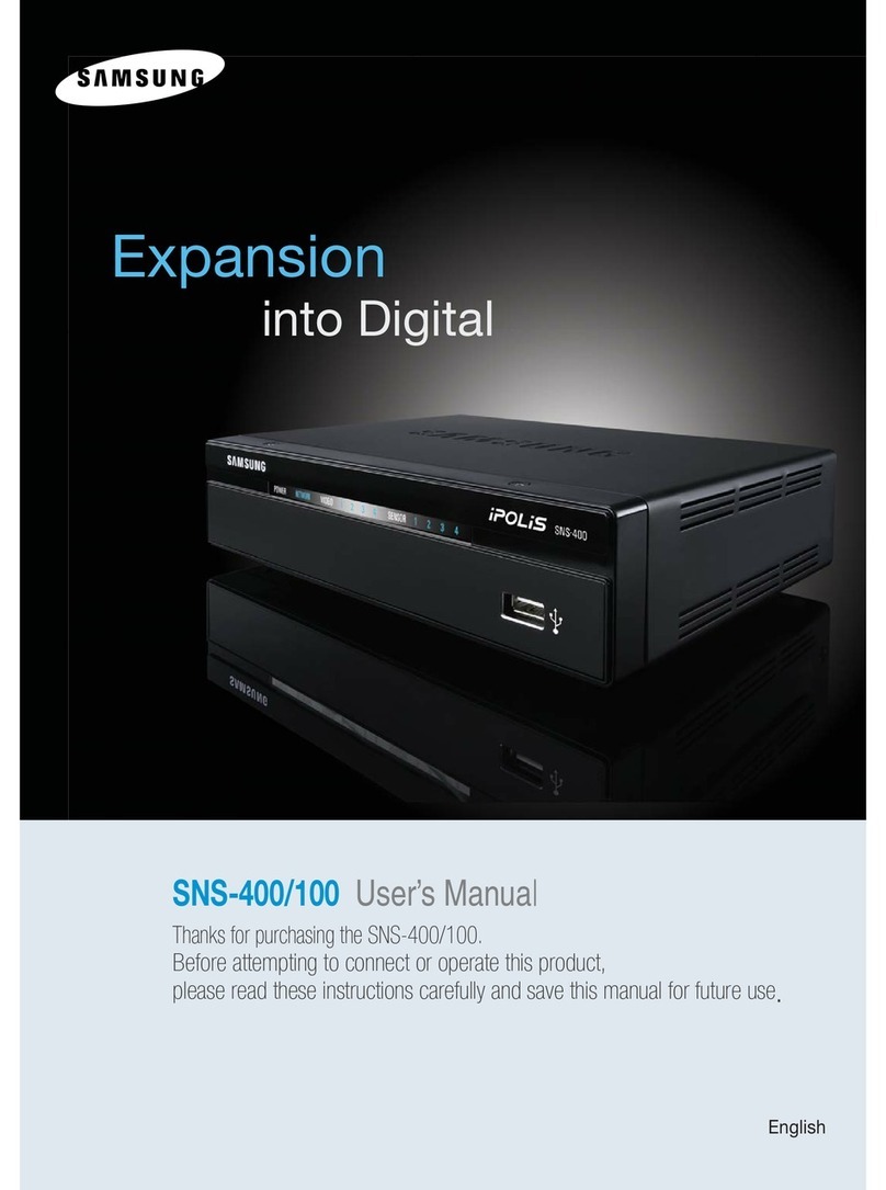
Samsung SmartServer 3840 User manual

Installation Guide

© Copyright SAMSUNG Electronics co., LTD. All rights reserved.

iii
Contents
Safety. . . . . . . . . . . . . . . . . . . . . . . . . . . . . . . . . . . . . . . . . . . . . . . . . . . . . . . . . . . . . v
Chapter 1. Introduction . . . . . . . . . . . . . . . . . . . . . . . . . . . . . . . . . . . . . . . . . . . . . . 1
Features and specifications . . . . . . . . . . . . . . . . . . . . . . . . . . . . . . . . . . . . . . . . . . . . 2
Notices and statements used in this book . . . . . . . . . . . . . . . . . . . . . . . . . . . . . . . . . 3
Before you begin. . . . . . . . . . . . . . . . . . . . . . . . . . . . . . . . . . . . . . . . . . . . . . . . . . . . . 3
Working inside a server with power on. . . . . . . . . . . . . . . . . . . . . . . . . . . . . . . . . . . . 4
Handling static-sensitive devices . . . . . . . . . . . . . . . . . . . . . . . . . . . . . . . . . . . . . . . . 4
Major components of the SS3840 server. . . . . . . . . . . . . . . . . . . . . . . . . . . . . . .5
Chapter 2. Installing options . . . . . . . . . . . . . . . . . . . . . . . . . . . . . . . . . . . . . . . . . . 7
Opening the cover. . . . . . . . . . . . . . . . . . . . . . . . . . . . . . . . . . . . . . . . . . . . . . . . . . . . 7
PCI and PCI-X adapters . . . . . . . . . . . . . . . . . . . . . . . . . . . . . . . . . . . . . . . . . . . . . . . 8
PCI and PCI-X adapter considerations. . . . . . . . . . . . . . . . . . . . . . . . . . . . . . . . . . . . 8
Installing adapters . . . . . . . . . . . . . . . . . . . . . . . . . . . . . . . . . . . . . . . . . . . . . . . . . 9
Cabling a ServeRAID adapter . . . . . . . . . . . . . . . . . . . . . . . . . . . . . . . . . . . . . . . 11
SMP Expansion Module . . . . . . . . . . . . . . . . . . . . . . . . . . . . . . . . . . . . . . . . . . . . . 13
Removing an SMP Expansion Module and cover . . . . . . . . . . . . . . . . . . . . . . . . . . 14
Installing and replacing a microprocessor . . . . . . . . . . . . . . . . . . . . . . . . . . . . . . 18
DIMMs . . . . . . . . . . . . . . . . . . . . . . . . . . . . . . . . . . . . . . . . . . . . . . . . . . . . . . . . . 23
Installing DIMMs. . . . . . . . . . . . . . . . . . . . . . . . . . . . . . . . . . . . . . . . . . . . . . . . . . 24
Reinstalling an SMP Expansion Module and cover . . . . . . . . . . . . . . . . . . . . . . . . . 26
Completing the installation . . . . . . . . . . . . . . . . . . . . . . . . . . . . . . . . . . . . . . . . . . . . 29
Working with cables . . . . . . . . . . . . . . . . . . . . . . . . . . . . . . . . . . . . . . . . . . . . . . . 30
SMP expansion cabling: . . . . . . . . . . . . . . . . . . . . . . . . . . . . . . . . . . . . . . . 31
Power cabling: . . . . . . . . . . . . . . . . . . . . . . . . . . . . . . . . . . . . . . . . . . . . . . . 31
RXE expansion cabling:. . . . . . . . . . . . . . . . . . . . . . . . . . . . . . . . . . . . . . . . 31
SCSI cabling:. . . . . . . . . . . . . . . . . . . . . . . . . . . . . . . . . . . . . . . . . . . . . . . . 32
USB cabling: . . . . . . . . . . . . . . . . . . . . . . . . . . . . . . . . . . . . . . . . . . . . . . . . 32
Video cabling: . . . . . . . . . . . . . . . . . . . . . . . . . . . . . . . . . . . . . . . . . . . . . . . 32
Auxiliary pointing device cabling:. . . . . . . . . . . . . . . . . . . . . . . . . . . . . . . . . 32
Keyboard cabling: . . . . . . . . . . . . . . . . . . . . . . . . . . . . . . . . . . . . . . . . . . . . 32
Gigabit Ethernet cabling: . . . . . . . . . . . . . . . . . . . . . . . . . . . . . . . . . . . . . . . 32
RXE Management cabling: . . . . . . . . . . . . . . . . . . . . . . . . . . . . . . . . . . . . . 32
Remote Supervisor Adapter cabling:. . . . . . . . . . . . . . . . . . . . . . . . . . . . . . 33
Chapter 3. Server power, controls, and options . . . . . . . . . . . . . . . . . . . . . . . . . 35
Server controls and indicators . . . . . . . . . . . . . . . . . . . . . . . . . . . . . . . . . . . . . . . . . 35
Front view. . . . . . . . . . . . . . . . . . . . . . . . . . . . . . . . . . . . . . . . . . . . . . . . . . . . . . . 35
Rear view . . . . . . . . . . . . . . . . . . . . . . . . . . . . . . . . . . . . . . . . . . . . . . . . . . . . . . . 37
Turning on the server . . . . . . . . . . . . . . . . . . . . . . . . . . . . . . . . . . . . . . . . . . . . . . 39
Turning off the server . . . . . . . . . . . . . . . . . . . . . . . . . . . . . . . . . . . . . . . . . . . . . . 40
Standby mode . . . . . . . . . . . . . . . . . . . . . . . . . . . . . . . . . . . . . . . . . . . . . . . . . . . 41
Chapter 4. Configuring your server . . . . . . . . . . . . . . . . . . . . . . . . . . . . . . . . . . . 43
Using the Configuration/Setup Utility program . . . . . . . . . . . . . . . . . . . . . . . . . . . . . 44
Using the SCSISelect utility program . . . . . . . . . . . . . . . . . . . . . . . . . . . . . . . . . . . . 44
Using the ServerGuide CD . . . . . . . . . . . . . . . . . . . . . . . . . . . . . . . . . . . . . . . . . . . . 45
Using the Remote Supervisor Adapter. . . . . . . . . . . . . . . . . . . . . . . . . . . . . . . . . . . 45
Using the ServeRAID configuration programs . . . . . . . . . . . . . . . . . . . . . . . . . . . . . 46
Chapter 5. Solving problems. . . . . . . . . . . . . . . . . . . . . . . . . . . . . . . . . . . . . . . . . 47
Diagnostic tools overview . . . . . . . . . . . . . . . . . . . . . . . . . . . . . . . . . . . . . . . . . . . . . 47
POST beep codedescriptions.. . . . . . . . . . . . . . . . . . . . . . . . . . . . . . . . . . . . . . . .47
iv Installation Guide
ServerGuide startup problems . . . . . . . . . . . . . . . . . . . . . . . . . . . . . . . . . . . . . . . . . 48
Troubleshooting charts . . . . . . . . . . . . . . . . . . . . . . . . . . . . . . . . . . . . . . . . . . . . . . . 49
Light Path Diagnostics feature overview. . . . . . . . . . . . . . . . . . . . . . . . . . . . . . . . . . 52
Identifying problems using the Light Path Diagnostics. . . . . . . . . . . . . . . . . . . . . 54
Light Path Diagnostics table. . . . . . . . . . . . . . . . . . . . . . . . . . . . . . . . . . . . . . . . . 55

v
Safety
Before installing this product, read the Safety Information.
Antes de instalar este produto, leia as Informações de Segurança.
Læs sikkerhedsforskrifterne, før du installerer dette produkt.
Lees voordat u dit product installeert eerst de veiligheidsvoorschriften.
Ennen kuin asennat tämän tuotteen, lue turvaohjeet kohdasta Safety Information.
Avant d'installer ce produit, lisez les consignes de sécurité.
Vor der Installation dieses Produkts die Sicherheitshinweise lesen.
Prima di installare questo prodotto, leggere le Informazioni sulla Sicurezza.
Les sikkerhetsinformasjonen (Safety Information) før du installerer dette produktet.
Antes de instalar este produto, leia as Informações sobre Segurança.
Pred instalací tohoto produktu si prectete prírucku bezpecnostních instrukcí.

vi Installation Guide
Antes de instalar este producto, lea la información de seguridad.
Läs säkerhetsinformationen innan du installerar den här produkten.
Statement 1:
DANGER
To Connect: To Disconnect:
1. Turn everything OFF.
2. First, attach all cables to devices.
3. Attach signal cables to connectors.
4. Attach power cords to outlet.
5. Turn device ON.
1. Turn everything OFF.
2. First, remove power cords from outlet.
3. Remove signal cables from connectors.
4. Remove all cables from devices.
Electrical current from power, telephone, and communication cables is
hazardous.
To avoid a shock hazard:
• Do not connect or disconnect any cables or perform installation,
maintenance, or reconfiguration of this product during an electrical
storm.
• Connect all power cords to a properly wired and grounded electrical
outlet.
• Connect to properly wired outlets any equipment that will be attached
to this product.
• When possible, use one hand only to connect or disconnect signal
cables.
• Never turn on any equipment when there is evidence of fire, water, or
structural damage.
• Disconnect the attached power cords, telecommunications systems,
networks, and modems before you open the device covers, unless
instructed otherwise in the installation and configuration procedures.
• Connect and disconnect cables as described in the following table
when installing, moving, or opening covers on this product or
attached devices.

Safety vii
Statement 2:
CAUTION:
When replacing the lithium battery,use onlyan equivalent type battery
recommended by the manufacturer.If your system has a module
containing a lithium battery,replace it only with the same module type
made by the same manufacturer. The battery contains lithium and can explode
if not properly used, handled, or disposed of.
Do not:
• Throw or immerse into water
• Heat to more than 100°C (212°F)
• Repair or disassemble
Dispose of the battery as required by local ordinances or regulations.
Statement 3:
CAUTION:
When laser products (such as CD-ROMs, DVD drives, fiber optic devices, or
transmitters) are installed, note the following:
• Do not remove the covers. Removing the covers of the laser product could
result in exposure to hazardous laser radiation. There are no serviceable
parts inside the device.
• Use of controls or adjustments or performance of procedures other than
those specified herein might result in hazardous radiation exposure.
DANGER
Some laser products contain an embedded Class 3A or Class 3B laser
diode. Note the following.
Laser radiation when open. Do not stare into the beam, do not view
directly with optical instruments, and avoid direct exposure to the beam.

viii Installation Guide
Statement 4:
CAUTION:
Use safe practices when lifting.
Statement 5:
CAUTION:
The power control button on the device and the power switch on the power sup-
ply do not turn off the electrical current supplied to the device. The device also
might have more than one power cord. To remove all electrical current from the
device, ensure that all power cords are disconnected from the power source.
≥18 kg (39.7 lb) ≥32 kg (70.5 lb) ≥55 kg (121.2 lb)
1
2

Safety ix
Statement 8:
CAUTION:
Never remove the cover on a power supply or any part that has the following
label attached.
Hazardous voltage, current, and energy levels are present inside any compo-
nent that has this label attached. There are no serviceable parts inside these
components. If you suspect a problem with one of these parts, contact a ser-
vice technician.

x Installation Guide

1
Chapter 1. Introduction
Thank youforpurchasing an SAMSUNG SmartServer 3840.
This Installation Guide provides the information that is needed to:
•Set up and cable your server
• Start and configure your server
• Install options
• Install your network operating system (NOS)
• Perform basic troubleshooting of your server
Your server comes with a limited warranty. If you have access to the World Wide Web,
you can obtain up-to-date information about your SmartServer 3840 model and other
SAMSUNG serverproducts at http://www.sec.co.kr/
The machine type and serial number are located on the ID label located on the left
side of the bezel just above the hard disk drives.
Record your product information in this table.
Product name _________________________________________________
Type _________________________________________________
Model number _________________________________________________
Serial number _________________________________________________
NOTE:FORPROPERAIRFLOW, REPLACEFANWITHIN2 MINUTES
FRONTOFBOX
NOTE:FORPROPERAIRFLOW, REPLACEFANWITHIN2 MINUTES
FRONTOFBOX
ID Label
5System Management Board
PCI Board
4
6I/O Board
CommonFRUNumbers
Midplane Board
3
Lower CEC
2
Upper CEC
1
Light-Path Diagnostics

2 Installation Guide
Features and specifications
The following table provides a summary of the features and specifications for your
SS3840.
Microprocessor:
• Supports the following
microprocessors (depending on
your configuration):
— Up to 8 Intel™Xeon™MP 1.4
GHz with 512 KB,1.5 GHz with
512 KB, 1.6 GHz with 1 MB
Level-3 cache
• IBM XA-32™chip set with
integrated memory, I/O, system
cache, and remote I/O controllers
Memory:
• Minimum: 2 GB
• Maximum: 32 GB (depending on
your configuration)
• Type: 4-way interleaved PC133
MHz, ECC SDRAM, registered
DIMMs only
• Supports 512 MB and 1GB dual
inline memory modules (DIMMs)
•XceL4
™Server Accelerator Cache
(up to 64 MB depending on your
configuration)
Drives:
• Diskette: 1.44 MB
• CD-ROM: 24X IDE
• Supports up to two internal
Ultra160 SCSI hard disk drives
Active™PCI-X expansion slots:
Six 64-bit Active PCI-X expansion
slots:
• Two 66 MHz PCI-X slots
• Two 100 MHZ PCI-X slots
• Two 133 MHZ PCI-X slots
• Additional PCI-X slots available in
an optional remote I/O expansion
enclosure
Cooling:
Four hot-swap fans
• Two 150 mm x 51 mm redundant
fans
• Two 150 mm x 38 mm fans
Power supply:
Two hot-swap power supplies (550
watts at 110 V ac or 1050 watts at 220
V ac)
Video:
• S3 Savage4 Pro video on system
board
• PCI bus interface
• Compatible with SVGA
• 8 MB SDRAM video memory at
125 MHz
Size (4U):
• Height: 17.8 cm (7 inches, 4U)
• Depth: 69.85 cm (27.5 inches)
• Width: 48.3 cm (19 inches)
• Maximum weight: 50 kg (110 lb)
depending on your configuration
Integrated functions:
• Broadcom 5700 10/100/1000
Ethernet controller
• Light Path Diagnostics™
• Adaptec 7899W Dual Ultra160
SCSI controller
• Remote Supervisor Adapter
(service processor)
— ASM interconnect (peer-to-
peer) port
— Ethernet port
— Serial port
• IDE controller
• RXE Management Port
• Three USB ports
• Keyboard port
• SCSI port
•Mouseport
• Symmetrical multiprocessor
(SMP) Expansion Ports (up to six
ports depending on your
configuration)
• Two remote I/O expansion
enclosure (RXE) Expansion Ports
Acoustical noise emissions:
• Sound power, idling: 6.2 bel
maximum
• Sound power, operating: 6.2 bel
maximum
Environment:
• Air temperature:
— Server on: 10°to 35°C (50.0°to
95.0°F). Altitude: 0 to 914 m
(2998.7 ft)
— Server on: 10°to 32°C (50.0°to
89.6°F). Altitude: 914 m
(2998.7 ft) to 2133 m (6998.0 ft)
— Server off: -40°to 60°C
(-104°to 140°F). Maximum
altitude: 2133 m (6998.0 ft)
• Humidity:
— Server on: 8% to 80%
— Server off: 5% to 100%
Heat output:
Approximate heat output in British
thermal units (Btu) per hour
• Minimum configuration: 855 Btu
(250 watts)
• Maximum configuration: 2726 Btu
(800 watts)
Electrical input:
• Sine-wave input (47-53 or 57-63 Hz)
required
• Input voltage low range:
— Minimum: 100 V ac
— Maximum: 127 V ac
• Input voltage high range:
— Minimum: 200 V ac
— Maximum: 240 V ac
• Input kilovolt-amperes (kVA)
approximately:
— Minimum: 0.250 kVA
— Maximum: 0.800 kVA

Chapter 1. Introduction 3
Notices and statements used in this book
The caution anddanger statementsusedin this bookalso appear in theSafety
Information book with the enclosure. Each caution and danger statement
is numbered for easy referenceto the corresponding statement in the safety book.
The notice and statement definitions are as follows:
•Note: These notices provide important tips, guidance, or advice.
•Important: These notices provide information or advice that might help you avoid
inconvenient or problem situations.
•Attention: These notices indicate possible damage to programs, devices, or
data. An attention notice is placed just before the instruction or situation in which
damage could occur.
•Caution: These statements indicate situations that can be potentially hazardous
to you. A caution statement is placed just before the description of a potentially
hazardous procedure step or situation.
•Danger: These statements indicate situations that can be potentially lethal or
extremely hazardous to you. A danger statement is placed just before the
description of a potentially lethal or extremely hazardous procedure step or
situation.
Before you begin
Before you begin to install options in your server, read the following information:
• Become familiar with the information provided in “Safety” on page v, and “Han-
dling static-sensitive devices” on page 4. These guidelines will help you work
safely while working with your server or options.
• Make sure that you have an adequate number of properly grounded electrical out-
lets for your server, monitor, and any other options that you intend to install.
• Back up all important data before you make changes to disk drives.
•For a list ofsupported options for the SS3840, refer to
http://www.sec.co.kr/ on the WorldWideWeb.
Note: Some preconfigured servers have a unique list of supported options. See the
software documentation provided with those servers for more information.

4 Installation Guide
Working inside a server with power on
Your server supports hot-swap devices and is designed to operate safely while turned
on with the cover removed. Follow these guidelines when you work inside a server
that is turned on:
• Avoid loose-fitting clothing on your forearms. Button long-sleeved shirts before
working inside the server; do not wear cuff links while you are working inside the
server.
• Do not allow your necktie or scarf to hang inside the server.
• Remove jewelry, such as bracelets, rings, necklaces, and loose-fitting wrist
watches.
• Remove items from your shirt pocket (such as pens or pencils) that could fall into
the server as you lean over it.
• Take care to avoid dropping any metallic objects, such as paper clips, hair pins, or
screws, into the server.
Handling static-sensitive devices
Attention: Static electricity can damage electronic devices and your system. To
avoid damage, keep static-sensitive devices in their static-protective package until you
are ready to install them.
To reduce the possibility of electrostatic discharge, observe the following precautions:
• Limit your movement. Movement can cause static electricity to build up around
you.
• Handle the device carefully, holding it by its edges or its frame.
• Do not touch solder joints, pins, or exposed printed circuitry.
• Do not leave the device where others can handle and possibly damage the device.
• While the device is still in its anti-static package, touch it to an unpainted metal
part of the system unit for at least 2 seconds. (This drains static electricity from the
package and from your body.)
• Remove the device from its package and install it directly into your system unit
without setting it down. If it is necessary to set the device down, place it in its
static-protective package. Do not place the device on your system unit cover or on
a metal table.
• Take additional care when handling devices during cold weather as heating
reduces indoor humidity and increases static electricity.

Chapter 1. Introduction 5
Major components of the SS3840 server
The following illustration shows the locations of major components in your server.
Note: The illustrations in this document might differ slightly from your hardware.
NOTE:FORPROPERAIRFLOW, REPLACEFANWITHIN2 MINUTES
FRONTOFBOX
NOTE:FORPROPERAIRFLOW, REPLACEFANWITHIN2 MINUTES
FRONTOFBOX
EMC Shield
(For single SMP Module)
SMP baffle
Retention bracket
SMP
Expansion
Module
DIMM
Heat-sink
Microprocessor
Fan 4
Hard disk
drive
CD-ROM
drive
VRM
Cover
Thumbscrews
DIMM
access
doors
Fan 3
Fan 1 Fan 2
Hot-swap
power supply
Bezel
Shipping thumbscrews
Center
plane

6 Installation Guide

7
Chapter 2. Installing options
This section provides basic information thatis needed to install PCI orPCI-X adapt-
ers, symmetrical multiprocessor (SMP) Expansion Modules, microprocessors, and
DIMMs; properly cable your server; and prepare your server for installation into a rack
cabinet.
Opening the cover
Complete the following steps to open the server cover:
Note: Before opening the top cover, you must remove the rack-support wheels and
handles from the server. Refer to the Rack Installation Instructions for informa-
tion on how to remove them.
1. Review the information in “Before you begin” on page 3, “Working inside a server
with power on” on page 4, and “Handling static-sensitive devices” on page 4.
2. Press the release latch on the left half of the top cover to the left.
3. Using the finger hole in the release latch, open the left half of the cover; then,
open the right half of the cover.
Attention: For proper cooling and airflow, close the cover before turning on the
server. Operating the server for extended periods of time (over 30 minutes) with
the cover open might damage server components.
NOTE:FORPROPERAIRFLOW, REPLACEFANWITHIN2 MINUTES
FRONTOFBOX
NOTE:FORPROPERAIRFLOW, REPLACEFANWITHIN2 MINUTES
FRONTOFBOX
Latch

8 Installation Guide
PCI and PCI-X adapters
This section provides information aboutthePCI-X expansion slots onthe I/Oboard,
and peripheral component interconnect (PCI) adapters.
The following illustration shows the location and bus speeds of the PCI-X expansion
slots on the I/O board.
Note: The illustrations in this document might differ slightly from your hardware.
PCI and PCI-X adapter considerations
Before you install adapters, review the following:
• Locate the documentation that comes with the adapter and follow those instruc-
tions in addition to the instructions in this chapter.
• If you need to change the switch settings or jumper settings on your adapter, fol-
low the instructions that come with the adapter.
• Video adapters are not supported.
• Some long adapters have extension handles or brackets installed. Before install-
ing the adapter, you must remove the extension handle or bracket.
• You can install both PCI and PCI-X adapters in the same bus. However, if you
install a PCI adapter and a PCI-X adapter in the same bus, the PCI-X features of
the PCI-X adapter will be disabled and the adapter will function as a PCI adapter.
• You can install PCI or PCI-X adapters of speeds faster than what is labeled for a
particular PCI-X bus. For example, if you install two 133 MHz adapters into slots
that are labeled as 100 MHz slots, the adapters will operate at 100MHz.
PCI-X slot 1
(66 )MHz
PCI-X slot 2
(66 )MHz
PCI-X slot 3
(100 )MHz
PCI-X slot 4
(100 )MHz
PCI-X slot 5
(133 )MHz
PCI-X slot 6
(133 MHz) Attention LED
Power LED

Chapter 2. Installing options 9
• If you install a 33 MHz and a 66 MHz adapter in the same bus, the bus speed will
match that of the slowest adapter.
• If a single 133 MHz adapter is installed in PCI-X Bus B (slot 3 and 4), and the
other slot in PCI-X Bus B is empty, the adapter will operate at 133 MHz.
• Your server supports six hot-plug 64-bit adapters in the expansion slots located on
the PCI-X board.
Note: You can add up to 12 additional PCI-X slots to your server by connecting
your server to a remote I/O expansion enclosure. For more information
about the expansion enclosure and how to connect your server to it, refer
to the documentation that comes with your expansion enclosure.
• Your server supports 3.3 V adapters; it does not support 5.0 V adapters.
• Your server uses a rotational interrupt technique to configure PCI-X adapters. You
can use this technique to install PCI-X adapters that currently do not support shar-
ing of PCI-X interrupts.
• The system scans PCI-X slots to assign system resources. The system attempts
to start the first device found. The search order is: CD-ROM, disk drives, inte-
grated SCSI devices, PCI-X slots (1, 2, 6, 5, 3, 4), and the integrated Ethernet
controller.
Note: You can use the Configuration/Setup Utility program to change the boot
precedence for your server. Select Start Options from the Configura-
tion/Setup Utility program main menu.
Installing adapters
The Active PCI-X slots in your server must be disabled by the operating system before
you insert or remove a PCI or PCI-X adapter.
Note: Before hot-swapping any of the PCI-X adapters, read the information in
“Working inside a server with power on” on page 4.
Complete the following steps to install an adapter:
1. Review the information in “Safety” on page v, “Before you begin” on page 3,
“Working inside a server with power on” on page 4, and “Handling static-sensitive
devices” on page 4.
2. Open the top cover.
Note: Inside your server there are six PCI-X slots: two 66 MHz, two 100 MHz,
and two 133 MHz. Before attempting to install a new adapter, be sure that
there is an available slot for it. If you need additional PCI-X slots, you can
purchase aremote I/O expansion enclosure either from your SAMSUNG
marketing representativeor authorized reseller.

10 Installation Guide
3. Refer to the documentation that comes with your adapter for any cabling instruc-
tions.
Note: Route adapter cables before you install the adapter.
4. Set any jumpers or switches as described by the adapter manufacturer.
5. Install the adapter:
a. Open the blue adapter guide by lifting the front edge, as shown in the illustra-
tion.
b. Carefully grasp the adapter by its top edge or upper corners, and align it with
the connector on the I/O board.
c. Press the adapter firmly into the adapter connector.
Attention: When you install an adapter, be sure the adapter is correctly
seated in the connector. Improperly seated adapters might cause damage to
the I/O board or to the adapter.
d. Push down on the blue adapter guide to keep the adapter steady.
e. Close the tab; then, push down on the blue adapter retention latch until it
clicks into place, securing the adapter.
6. Connect the internal cables to the adapter.
7. If you have other options to install or remove, do so now.
8. Go to “Completing the installation” on page 29.
NOTE: FOR PROPERAIRFLOW, REPLACE FAN WITHIN 2 MINUTES
FRONT OF BOX
NOTE: FOR PROPERAIRFLOW, REPLACE FAN WITHIN 2 MINUTES
FRONT OF BOX
Tab
Ad
apter
retention
latch
Attention
LED
Power
LED
Adapter guide
PCI-X
divider
This manual suits for next models
1
Table of contents
Other Samsung Server manuals

Samsung
Samsung MIM-D00 User manual

Samsung
Samsung MIM-D00 User manual

Samsung
Samsung MIM-D00 User manual

Samsung
Samsung Webthru SWC 306 User manual

Samsung
Samsung TC222L User manual

Samsung
Samsung ML-2010 - B/W Laser Printer User manual

Samsung
Samsung SNT-1010 User manual

Samsung
Samsung SBB-SNOWJAU User manual

Samsung
Samsung SPE-400 User manual

Samsung
Samsung SMARTSERVER 370 User manual