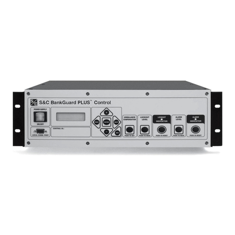
S&C IntelliTEAM II User manual

S&C IntelliTEAM II®Universal Interface Module
Instruction Sheet 1043-550
November 17, 2008© S&C Electric Company
Troubleshooting Instructions
Table of Contents
Section Page Section Page
Introduction
Qualified Persons . . . . . . . . . . . . . . . . . . . . . . . . . . 2
Read this Instruction Sheet . . . . . . . . . . . . . . . . . . 2
Retain this Instruction Sheet . . . . . . . . . . . . . . . . . . 2
Latest Document Release . . . . . . . . . . . . . . . . . . . . 2
Warranty . . . . . . . . . . . . . . . . . . . . . . . . . . . . . . . . . 2
Safety Information
Understanding Safety-Alert Messages . . . . . . . . . . 3
Following Safety Instructions. . . . . . . . . . . . . . . . . . 3
Replacement Instructions and Labels . . . . . . . . . . 3
Troubleshooting Problems
Applicable Software. . . . . . . . . . . . . . . . . . . . . . . . . 4
Troubleshooting Overview . . . . . . . . . . . . . . . . . . . . 4
Display Problems. . . . . . . . . . . . . . . . . . . . . . . . . . . 6
Error Messages . . . . . . . . . . . . . . . . . . . . . . . . . . . . 6
Software Troubleshooting . . . . . . . . . . . . . . . . . . . . 7
Using IntelliLINK to Locate Problems . . . . . . . . . . . 9
Navigating the IntelliLINK Screens . . . . . . . . . . . . 10
Communication Diagnosis. . . . . . . . . . . . . . . . . . . 13
Team Problems
Team Operation Screens. . . . . . . . . . . . . . . . . . . . 17
Individual Team Member Status . . . . . . . . . . . . . . 21
Team Member Task Operations. . . . . . . . . . . . . . . 27
Contract Status . . . . . . . . . . . . . . . . . . . . . . . . . . . 28
Team Member Action Path . . . . . . . . . . . . . . . . . . 31
Coach Activity . . . . . . . . . . . . . . . . . . . . . . . . . . . . 33
Data Logging
Data Logging Setup. . . . . . . . . . . . . . . . . . . . . . . . 34
Historic Event View . . . . . . . . . . . . . . . . . . . . . . . . 39
Logging Status Points . . . . . . . . . . . . . . . . . . . . . . 65
Special Event Counters . . . . . . . . . . . . . . . . . . . . 72
System Startup History . . . . . . . . . . . . . . . . . . . . . 75
Historic Event Log . . . . . . . . . . . . . . . . . . . . . . . . . 76
Compact Flash Log . . . . . . . . . . . . . . . . . . . . . . . . 77
Viewing Compact Flash Data . . . . . . . . . . . . . . . . 77

2 S&C Instruction Sheet 1043-550
Qualified Persons ÇWARNING
The equipmentcoveredby thispublication mustbe installed,operated,and maintainedby
qualified persons who are knowledgeable in the installation, operation, and maintenance
of overhead electric power distribution equipment along with the associated hazards.
A qualified person is one who is trained and competent in:
• The skills and techniques necessary to distinguish exposed live parts from non-
live parts of electrical equipment.
• The skills and techniques necessary to determine the proper approach distances
corresponding to the voltages to which the qualified person will be exposed.
• The proper use of the special precautionary techniques, personal protective
equipment, insulating and shielding materials, and insulated tools for working on
or near exposed energized parts of electrical equipment.
These instructions are intended only for such qualified persons. They are not
intended to be a substitute for adequate training and experience in safety procedures
for this type of equipment.
Read this Instruction
Sheet
Thoroughly and carefully read this instruction sheet before programming, operating, or
maintaining your S&C Universal Interface Module. Familiarize yourself with the safety
information on page 3. The latest version of this instruction sheet is available online in
PDF format at www.sandc.com. Select: Support/Product Literature Library.
Retain this Instruction
Sheet
This instruction sheet is a permanent part of your S&C IntelliRupter. Designate a location
where you can easily retrieve and refer to this publication.
Warranty The standard warranty contained in S&C’s standard conditions of sale, as set forth in
Price Sheet 150, applies to the Universal Interface Module, except that the first paragraph
of said warranty is replaced by the following:
(1) General: Seller warrants to immediate purchaser or end user for a period of 10
years from the date of shipment that the equipment delivered will be of the kind and
quality specified in the contract description and will be free of defects of workmanship
and material. Should any failure to conform to this warranty appear under proper and
normal use within ten years after the date of shipment the seller agrees, upon prompt
notification thereof and confirmation that the equipment has been stored, installed, oper-
ated, inspected, and maintained in accordance with recommendations of the seller and
standard industry practice, to correct the nonconformity either by repairing any dam-
aged or defective parts of the equipment or (at seller’s option) by shipment of necessary
replacement parts. The seller’s warranty does not apply to any equipment that has been
disassembled, repaired, or altered by anyone other than the seller. This limited warranty
is granted only to the immediate purchaser or, if the equipment is purchased by a third
party for installation in third-party equipment, the end user of the equipment. The seller’s
duty to perform under any warranty may be delayed, at the seller’s sole option, until the
seller has been paid in full for all goods purchased by the immediate purchaser. No such
delay shall extend the warranty period.
Replacement parts provided by seller or repairs performed by seller under the war-
ranty for the original equipment will be covered by the above special warranty provision
for its duration. Replacement parts purchased separately will be covered by the above
special warranty provision.
Warranty of the Universal Interface Module is contingent upon the installation, configu-
ration, and use of the control or software in accordance with S&C’s applicable instruction
sheets. This warranty does not apply to major components not of S&C manufacture, such
as batteries, and communication devices. However, S&C will assign to immediate pur-
chaser or end user all manufacturer’s warranties that apply to such major components.
Introduction

S&C Instruction Sheet 1043-550 3
Understanding
Safety-Alert Messages
There are several types of safety-alert messages which may appear throughout this
instruction sheet as well as on labels attached to the Universal Interface Module.
Familiarize yourself with these types of messages and the importance of the various
signal words, as explained below.
ÇDANGER
“DANGER” identifies the most serious and immediate hazards which will likely
result in serious personal injury or death if instructions, including recommended
precautions, are not followed.
ÇWARNING
“WARNING” identifies hazards or unsafe practices which can result in serious
personal injury or death if instructions, including recommended precautions, are
not followed.
ÇCAUTION
“CAUTION” identifies hazards or unsafe practices which can result in minor per-
sonal injury or product or property damage if instructions, including recommended
precautions, are not followed.
NOTICE
“NOTICE” identifies important procedures or requirements that can result in product
or property damage if instructions are not followed.
Following
Safety Instructions
If you do not understand any portion of this instruction sheet and need assistance,
contact your nearest S&C Sales Office or S&C Authorized Distributor. Their tele-
phone numbers are listed on S&C’s website www.sandc.com. Or call S&C Headquarters
at (773) 338-1000; in Canada, call S&C Electric Canada Ltd. at (416) 249-9171.
NOTICE
Read this instruction sheet thoroughly and carefully
before installing or operating your S&C Universal
Interface Module.
Replacement
Instructions and Labels
If you need additional copies of this instruction sheet, contact your
nearest S&C Sales Office, S&C Authorized Distributor, S&C Headquarters, or S&C Elec-
tric Canada Ltd.
It is important that any missing, damaged, or faded labels on the equipment be replaced
immediately. Replacement labels are available by contacting your nearest S&C Sales
Office, S&C Authorized Distributor, S&C Headquarters, or S&C Electric Canada Ltd.
Safety Information

4 S&C Instruction Sheet 1043-550
Applicable Software These instructions were prepared for use with software UIMD3C1X, Rev. 1.3.
You can find the revision number on the Setup disk label and on the main screen of the UIM,
called the PRESENT CONDITIONS screen. For questions regarding the applicability of
information in this chapter to future software releases, please contact S&C.
ÇWARNING
These instructions do NOT replace the need for utility operation standards. Any
conflict between the information in this document and utility practices should be
reviewed by appropriate utility personnel and a decision made as to the correct
procedures to follow.
Serious risk of personal injury or death may result from contact with electric distribu-
tion equipment when electrical isolation and grounding procedures are not followed.
The equipment described in this document must be operated and maintained by
qualified persons who are thoroughly trained and understand any hazards that may
be involved. This document is written only for such qualified persons and is not a
substitute for adequate training and experience in safety procedures for accessing
high voltage equipment.
The Universal Interface Module and host control are connected to switchgear operat-
ing at primary voltage levels. High voltage may be present in the wiring to the switch
control or the switch control itself during certain failures of the switchgear wiring
or grounding system, or due to a failure of the switch itself. For this reason, access
to the switch control should be treated with the same safety precautions that would
be applied when accessing other high voltage lines and equipment. Follow all locally-
approved safety procedures when working on or around this switch control.
Before attempting to access an existing switch installation, check carefully for vis-
ible or audible signs of electrical or physical malfunction (do this before touching
or operating the switch control or any other part of the installation). These warning
signs include such things as smoke, fire, open fuses, crackling noises, loud buzzing,
etc. If a malfunction is suspected, treat all components of the installation, including
the switch control and associated mounting hardware, as if they were elevated to
primary (high) voltage.
Whenever you are manually reconfiguring the circuit (for example, during repairs),
follow your company’s operating procedures to disable automatic operation of the
IntelliTEAM II system. This prevents any unexpected operation of a team member.
You can disable the IntelliTEAM II system by pressing the automatic operation
ENABLE/DISABLE faceplate button to DISABLE on the faceplate of any active
5800 based team member of the team you want to disable, or turn on Prohibit Res-
toration on the UIM faceplate.
Troubleshooting
Overview
The following tools and Interface Module features are used to diagnose and correct
problems.
LCD
The LCD on the faceplate provides information about the present state of the team. For
an explanation of the faceplate and the LCD, see Instruction Sheet 1043-540.
Troubleshooting Problems

S&C Instruction Sheet 1043-550 5
NOTICE
If the suggested troubleshooting steps do not resolve the problem, call S&C at (773)
338-1000 for assistance.
Figure 1. Rack-Mounted Universal Interface Module.
LEDs
The LEDs on the Interface Module faceplate provide information about the state of the
control. For an explanation of the faceplate LEDs, see Instruction Sheet 1043-540.
IntelliLINK software
The OPERATION screens and TROUBLESHOOTING screens display information about
the Interface Module and its operation. For an explanation of these screens, see Using
IntelliLINK to Locate Problems on page 9.
To view these screens, you need a portable IBM/PC-compatible computer, a serial cable, and
the IntelliLINK version for the Interface Module. For more information about the equipment
required and how to use the IntelliLINK software, see Instruction Sheet 1043-540.
Figure 2. Panel-Mounted Universal Interface Module.
Troubleshooting Problems

6 S&C Instruction Sheet 1043-550
LCD is blank or you cannot scroll the data, or is not lighted
Check the LEDs. If all the Interface Module LEDs are OFF, the Interface Module is not
receiving power.
Check control power. Following utility-approved work procedures and safety practices,
verify that there is correct voltage in the line which provides control power.
The IntelliLINK software may display an error message while trying to establish commu-
nications with the Interface Module or a snapshot. If an error message appears, follow the
corrective action given below for that message.
IntelliLINK software won’t start
A. Close other software programs. Some software applications (such as HotSync®
technology for Palm™ handhelds) may interfere with the IntelliLINK software being
able to access your computer’s serial port. You should exit any program that might
take control of a serial port while using the IntelliLINK software.
B. Reinstall the IntelliLINK software on your computer. There may be a problem
with one of the files. See To Install the IntelliLINK Software in 1043-530.
“Could not connect to control on COM1”
See Opening port COM1... Trying 38400 BAUD... Connection Failed below.
“Incompatible Ident”
The IntelliLINK software uses a different screenset (WMN file) for each type of control and
normally selects the screenset for you. This message appears when you have a screenset
selected (displayed) and try to connect to a snapshot that requires a different screenset.
Use the correct screenset. To close the open screenset, click File > Close Screenset. Then
click File > Open Snapshot. In the Open Controller Data File dialog box, select the snapshot
you want to view, then click OK to open both the snapshot and the correct screenset.
“IntelliLINK setup incorrect or incomplete“
Reinstall the IntelliLINK software on your computer. There may be a problem with
one of the files. See To Start the IntelliLINK Software in 1043-530 for details.
“Opening port COM1... Trying 38400 BAUD... Connection Failed”
These messages appear in the Connect dialog box when the IntelliLINK software in your
computer cannot establish communication with the software in the Interface Module.
A. Check that the Interface Module has power. If the LCD is blank, the Interface
Module may have no power and cannot communicate with your portable computer.
See LCD is blank or you cannot scroll the data on page 7.
B. Check the serial cable connections. Check that you plugged your serial cable
into the LOCAL COMM. PORT on the Interface Module faceplate. Check that you
plugged the cable into the correct port on your computer (usually COM1 on portable
computers).
C. Try another communications port. The COM1 port on your computer may be
broken or assigned to a different device. Connect the cable to another comm port.
In the Connect dialog box, click the Change Setup button. From the pull-down list,
select the name of the port where you connected the cable. Click Connect.
Display Problems
Error Messages
Troubleshooting Problems

S&C Instruction Sheet 1043-550 7
D. Use a different serial cable. The serial cable between your computer and the
switch control may have a broken wire or pin. The cable may be wired for use with
a different kind of computer, or it may be a null-modem cable.
E. Check the serial port on your computer. Test the serial port by trying to com-
municate with a modem or other serial device.
“Program in the control: XXXX... not configured for this program”
Reinstall the IntelliLINK software on your computer. Make sure that you are install-
ing the correct IntelliLINK software for this Interface Module. For details, see To Install
The IntelliLINK Software in 1043-530.
“Software in control incompatible with open screenset... cannot be established”
The IntelliLINK software uses a different screenset (WMN file) for each type of control and
normally selects the screenset for you. This message appears when you have a screenset
selected (displayed) and try to connect to a control that requires a different screenset.
Use the correct screenset. To close the open screenset, click File > Close Screenset. Then
click File > Open Screenset and choose the correct screenset for the Interface Module.
Once the screenset opens, click Connection > Connect to Device.
“Software in control is XXXX... not properly configured for this product”
Reinstall the Setup software on your computer. There may be a problem with one of
the files. For details, see To Install The IntelliLINK Software in 1043-530.
“Times New Roman font is not on your system. The project requires it.”
Click OK to close the dialog box. If the program cannot find the desired font, it warns
you and then uses a different font.
Team Does Not Communicate
IMPORTANT: Carry out the following general procedure at each member of the team
– starting at the team member that is the most likely source of the problem.
A. Check the link between the switch control and its team communications
device. Check that the communications cabling is firmly in place at both ends, and
that the communications device has power.
B. Check all other communications ports that are being used. If the interface
module is directly connected to another team member, Interface Module connected
to host control device, or there is a radio or cable connection to a SCADA master
station, check all those cable connections. Test communication between the interface
module and the other devices.
C. Check the SETUP: Communications screen settings. Make sure the baud rates,
RTS active durations, and duplex settings are correct for the installed communica-
tions hardware.
D. If this switch control/Interface Module uses a radio, check the radio antenna.
Check that the radio antenna is in place and that the antenna cable is attached at
both ends.
E. If this switch control/Interface Module uses a radio, check radio connectiv-
ity. Check that the radio at this location can see all the other radios that it should
see. For more details, see the manufacturer’s documentation.
Software
Troubleshooting
Troubleshooting Problems

8 S&C Instruction Sheet 1043-550
Team does not reconfigure the circuit
A. Check the Team Logic setpoint. Connect your computer to the switch control/
Interface Module and start the IntelliLINK software. On the SETUP: Team screen,
check that the Team Logic setpoint is enabled for this team.
B. Check the other SETUP: Team screen settings. Make sure the DNP/RTU Address
is correct for each team member. Also, check that the normal switch position in the
Normal Open/Close setpoint is correct for each switch in the team, and that the
normal switch function is correct in the Normal Sw Func setpoint. Make sure that
the Maximum Capacity settings are appropriate for the circuit conditions.
C. Check the values on the TEAM OPERATION screen. Make sure that the Ready
Status reads READY. If not, check the Operational Status, Line Status, and Con-
figuration Status fields for reasons that the team may not be ready.
D. Check team communications. See Team Does Not Communicate on page 7.
E. Check the circuit configuration. Make sure that the circuit has not been temporar-
ily reconfigured due to construction or maintenance.
F. Check whether an event was logged. Check the DATA LOGGING HISTORIC
EVENTS screen to see whether the switch control detected and took action on an
event.
Team does not return the circuit to normal
A. Check the Return to Norm Mode setpoints. Connect your computer to the
Universal Interface Module and start the IntelliLINK software. On the SETUP: Team
screen, check that the “Rtn to Norm Mode” setpoint is set properly for this team (Open
or Closed).
B. Check the present operation mode for each team member. On the TEAM
OPERATION screen, make sure that the Ready Status reads READY. If not, check
the Operational Status, Line Status, and Configuration Status fields for reasons
that the team may not be ready.
C. Check team communications. See Team does not communicate on page 7.
D. Be sure automatic operation was not disabled. If automatic operation was dis-
abled at any team member while the circuit was in its reconfigured state, the Return
to Normal process is canceled.
LCD shows “ALARM” or “FAULT”
Check the TEAM OPERATION screen. Check the Operational Status, Line Status,
and Configuration Status fields for the reason(s) that the team is not ready.
DNP communications between PC and team members is not working
A. Check team communications. See Team does not communicate on page 7.
B. Check that the DNP cable is connected. Make sure that the serial cable from your
computer is connected to the cable from the DNP port (usually Port A). Also check
that the DB9 connector is fully seated in the DNP port.
C. Check the protocol and DNP address being used by the IntelliLINK software.
Start the IntelliLINK software on your computer. Select Tools > Options > Communi-
cation Setup. Make sure that DNP is the selected protocol. Also check that the Peer
Address matches the “DNP/RTU Address” for the team member with which you are
trying to communicate. Be sure the timeout and the baud rate are set appropriately
as well.
Troubleshooting Problems

S&C Instruction Sheet 1043-550 9
D. Check for error messages on the HISTORIC EVENT VIEW screen. To perform this
check, connect directly to the faceplate communications port and select “ICP” in
the IntelliLINK Communications Setup dialog box. See “HISTORIC EVENT VIEW
Screen” on page 35 for more details.
SCADA commands are ignored by the Interface Module/Host control device
A. Check for Interface Module power.
B. Check the RTU address. At the SETUP: Communications screen, check
which Communications RTU Address is used by this switch control. Make sure
the SCADA master station is sending commands for this control to the correct
address.
C. Check your communications hardware. See the manufacturer’s documentation
for details.
The LOCAL OPERATION, TEAM OPERATION, and TROUBLESHOOTING screens
can help you check the present status of:
• this Universal Interface Module
• other team members
• team operations
These screens can also help you locate the cause of various team and team member
problems.
Using IntelliLINK to
Locate Problems
Troubleshooting Problems

10 S&C Instruction Sheet 1043-550
IntelliLINK Menu
Navigation Buttons
The Tree button, at the right of the Main button, opens the Select Screen dialog box, and
presents an expandable tree view of the UIM Screenset, similar to Windows Explorer.
Double click on the screen name that you want to go to.
View the Present Conditions Screen
The PRESENT CONDITIONS screen (Figure 3) shows the present status of various switch
control settings, any existing fault and error conditions.
To display the PRESENT CONDITIONS screen:
Click the Main button at the bottom of any IntelliLINK screen to go to the PRESENT
CONDITIONS screen.
Navigating the
IntelliLINK Screens
The Main button, at the bottom of each screen, takes you back to the Present Conditions
screen, which is the main screen for UIM IntelliLINK Software. From this screen you can
get to all other screens. You can also return to the Present Conditions screen, by opening
the Window menu, and selecting Show Main Screen.
Troubleshooting Problems

S&C Instruction Sheet 1043-550 11
Figure 3. PRESENT CONDITIONS Screen.
This screen includes the following fields:
External Device Present Conditions
Switch Position
Once the binary status points are entered for switch position and the Interface Module is
polling the external device, the present switch position will be displayed here. Anything
other than open and close will be reported as bad contacts.
Remote Mode
Once the binary status point is entered for remote mode and the Interface Module is
polling the external device, the state of the remote mode will be displayed here. If not
programmed an N.A. will be displayed.
Fault Status
This field will follow the phase fault status points. If all points are inactive, Normal will be
displayed, Fault Detected will be displayed on any or all points that are active.
Error/Trouble Status
Any active alarms out in Data Logging, Logging Status Points will cause the message
“Problems Present - Check Data Logging Screens”.
Interface Module Present Conditions
Prohibit Restoration
When Prohibit Restoration becomes active from the front panel or from IntelliTEAM II,
Enabled will be displayed, else Disabled will be displayed.
Troubleshooting Problems

12 S&C Instruction Sheet 1043-550
Auto Operation Status
When IntelliTEAM initiates extended phase loss or 3 phase voltage loss open commands
to the external device, “Extended voltage loss trip” will be displayed, else “Idle” will be
displayed.
Interface Module Information
Software Product Name
This is the S&C name for the application software present in this Interface Module.
Product Version
The first two bytes 00.09 are the firmware revision bytes. 00 is the major version with 09
being the minor version. IntelliLINK uses these two bytes to match the screen set to the
application version loaded into the Interface Module. The remaining two bytes 00.02 are
the application build revision.
Product Version Codes
These eight bytes are unique to this firmware/product revision. These codes along with
the above Product Version are used to identify software installed in the field when trouble-
shooting concerns are being addressed.
EOS Version
The version of the operating system is displayed here.
Interface Module Commands
Clear Manual Switch Operations
When IntelliTEAM II has taken a team out of ready because of a manual operation, or a
NO OPERATION report was encountered, use this command to clear the internal error.
Troubleshooting Problems

S&C Instruction Sheet 1043-550 13
Figure 4. Communications Diagnostics for the Universal Interface Module.
To display the Communications Diagnostics screen:
From the PRESENT CONDITIONS screen select the Comm Menu button, and click the
Comm Stats button to display the Communications Diagnostics screen (Figure 4).
This screen contains counters and statistics associated with DNP communications
and the IntelliTEAM II system. This page tracks communications statistics for each
team member in the team(s) where this control is a member.
RTU Address
This field shows the “DNP/RTU Address” for the team member associated with the
counts in the column below.
Xmit Count
This field shows the number of original packets transmitted to a single team mem-
ber.
Retry Count
This field shows the number of packets transmitted to a single team member due to
a retry of an original packet.
Fail Count
This field shows the number of communications failures with a single team mem-
ber.
Last 2way
This field shows the latency (in seconds) associated with the last request sent to a
single team member.
Min 2way
This field shows the minimum latency (in seconds) recorded for a request sent to a
single team member.
Communication Diagnosis

14 S&C Instruction Sheet 1043-550
Max 2way
This field shows the maximum latency (in seconds) recorded for a request sent to a
single team member.
Avgd 2way
This field shows the average latency (in seconds) recorded for requests sent to a
single team member.
Last Cleared
A timestamp is displayed here that indicates the last time “Clear All” was performed.
This timestamp will assist you in determining the usefulness of the counters presented
on both Various Counters screens. If the counters have not been recently cleared,
then they may not represent present communications performance.
Figure 5. SETUP: Communications Diagnostics for the Universal Interface Module.
To display the Communications Diagnostics screen:
From the PRESENT CONDITIONS screen select the Comm Menu button, and click the
Comm Stats button to display the Communications Diagnostics screen, then click “Pg
Dn”.
This screen contains diagnostic information regarding communications related buffers
within this control. This information may be useful when talking with S&C personnel
about communications related issues.
Transport Function Receive List
This is the number of DNP frames that have been received and placed in the Transport
Function frame buffer. A frame may remain in this buffer if it is part of a multi-frame
fragment for which all frames have yet to be received, or it may remain in this buf-
fer for a limited time if the application layer is busy and can not yet accept the new
frame.
Communication Diagnosis

S&C Instruction Sheet 1043-550 15
Transport Function Transmit List
This is the number of DNP fragments that have been processed by the application
layer and are waiting for Data Link Layer service. A fragment may remain in this
buffer for a limited time if the Data Link Layer is busy.
Application Layer Message List
This is the number of application layer messages that are waiting to be processed
and/or serviced by the Transport Function. These messages primarily consist of
originated messages destined for team members for which responses are expected.
These originated messages will remain in the buffer until a response is received or
until the retry time and count have expired.
Peer Device List
This is the number of peer devices, or team members, that have been registered with
DNP and for which an association will be maintained.
Special Function List
This is the number of special functions that have been registered with DNP. Special
functions are application processes that will be triggered by read or write operations
to special predefined virtual memory locations.
URBE Function List
This is the number of functions, or application processes, that have been registered
with DNP which will be triggered by the reception of unsolicited event messages
from specific peer devices.
Binary Input Point List
This is the total number of binary input points that may be mapped to SCADA point
numbers. This is the size of the buffer rather than the actual number of mapped
points.
Analog Input Point List
This is the total number of analog input points that may be mapped to SCADA point
numbers. This is the size of the buffer rather than the actual number of mapped
points.
Counter Input Point List
This is the total number of counter input points that may be mapped to SCADA point
numbers. This is the size of the buffer rather than the actual number of mapped
points.
Control Output Point List
This is the total number of control output points that may be mapped to SCADA
point numbers. This is the size of the buffer rather than the actual number of mapped
points.
Analog Output Point List
This is the total number of analog output points that may be mapped to SCADA point
numbers. This is the size of the buffer rather than the actual number of mapped
points.
Binary Event List
This is the number of binary input events that are queued and ready to be sent in the
next event data request, or the next unsolicited event report.
Analog Event List
This is the number of analog input events that are queued and ready to be sent in the
next event data request, or the next unsolicited event report.
Communication Diagnosis

16 S&C Instruction Sheet 1043-550
Counter Event List
This is the number of counter input events that are queued and ready to be sent in
the next event data request, or the next unsolicited event report.
Route Table List
This is the number of routing table entries that have been registered with DNP. These
entries originate from the “SETUP: Communications Routing” screen.
Troubleshooting Problems

S&C Instruction Sheet 1043-550 17
Team Operation Screens The TEAM OPERATION screens show the present status of various team-related param-
eters for all members of the team.
To display the TEAM OPERATION MENU screen:
Click the Team Menu Button from the PRESENT CONDITIONS screen.
Figure 6. TEAM OPERATION MENU Screen.
The TEAM OPERATION MENU screen (Figure 6) shows a summary of the DNP/RTU
addresses for the teams where the Universal Interface Module is a member, and the pres-
ent Ready Status of each of the active teams.
To display one of the TEAM OPERATION screens:
At the TEAM OPERATION MENU screen, click the OPER button for the team you want to
access. The IntelliLINK software will display Page 1 of the corresponding TEAM OPERA-
TION screen.
Team Problems

18 S&C Instruction Sheet 1043-550
Figure 7. Page 1 of the TEAM OPERATION Screen.
Page 1 of the TEAM OPERATION screen (Figure 5) shows the present status of various
team-related parameters and information for each team member.
Team ID
This is the name you entered in the Team ID setpoint on the SETUP: Team screen.
Ready Status
If the Operational Status, Line Segment Status, and Configuration Status all indicate that
no errors are present, READY appears in this field. If errors are present, ALARM appears.
FAULT will be displayed if the team is isolating a faulted line segment.
Team Problems

S&C Instruction Sheet 1043-550 19
Operational Status
This is the operational status of the system. When the team members can perform team
operations, this field reads Good. Other Possible values are:
Coordination The team coach is not being passed throughout the team,
causing a lack of team coordination.
Remote Config The configuration of an adjacent team member is not consis-
tent with the local team member’s configuration.
Local Config There has been a change to the local team configuration on
the SETUP: Team screen that has not yet been accepted.
Remote Error An adjacent team member is indicating an error condition.
Local Error The local switch is disabled because Prohibit Restoration is
ON, or because the switch has changed state from a faceplate
or SCADA operation.
Logic Disabled The team logic has been disabled on the SETUP: Team
screen.
Not In Use This team is not in use.
No 2nd Contin. The team is in a transferred state, but if an additional event
occurs, no further transfer is allowed.
Configuration Status
This is the status of the user configuration parameters essential for team operation. Pos-
sible values are:
NoRTU Addr No RTU address was specified on the SETUP: Communica-
tions screen.
Stop + Data Chg The “Team Setup” setpoint is in a “Stopped” state follow-
ing a change made to the team parameters on the SETUP:
Team screen.
Stopped The “Team Setup” setpoint is disabled on the SETUP: Team
screen.
Data Change An unexpected change has been made to the team param-
eters on the SETUP: Team screen.
Record Count The count of team member records on the SETUP: Team
screen is incorrect. The team database must have at least
one record to be valid.
Not 1 Source An incorrect number of source switches was configured on
the SETUP: Team screen. A team may have one and only
one source switch.
No Local Rec No local record was found in the team database. One of the
team records must contain an RTU address that matches the
“DNP/RTU Address” entered on the SETUP: Communica-
tions screen.
Team Problems

20 S&C Instruction Sheet 1043-550
Line Segment Status
This is the fault and voltage loss status of the line segment protected by this team of con-
trols. If no fault or voltage loss is detected, this field reads “Good.” The field can include
a combination of possible values:
Segment Dead (Dd) The line segment is deenergized.
Segment Open (Op) All team switches are in the open position in preparation for
a circuit reconfiguration.
Overcurrent (OC) An overcurrent fault has been detected on the line segment
protected by this team of controls.
Voltage Loss (VL) A voltage loss event has been detected on this line segment
before this transfer event occurred.
Team Error (Er) An error has been detected within the team, affecting the
accuracy of the “Line Segment Status.”
Alt Source (AS) The line segment is being fed by an alternate source, either
directly from an adjacent line segment, or indirectly from
another location.
Local Real-Time Load
This is the 2-minute averaged measured 3-phase load (in amps) on the line segment pro-
tected by this team. This averaged load does not include the load measured beyond any
of the switches serving load outside of the local line segment.
Real Capacity
This is the loading capacity available on the line segment protected by this team. This value
takes into account the real capacity of any source-side teams, the maximum capacity of
the team’s present source switch, and any load that has already been transferred during
team circuit reconfiguration.
Team Problems
Table of contents
Other S&C Control Unit manuals
Popular Control Unit manuals by other brands

Pioneer
Pioneer CU-AV200 operating instructions

Watts
Watts iDROSET CF Series installation manual

ADTRAN
ADTRAN Quad T1 user manual

Metso
Metso jamesbury B Installation maintenance and operating instructions

Grundfos
Grundfos CIM 500 Installation and operating instructions

Festo
Festo VOFA-L26-T32C-M-G14-1C1 Series operating instructions