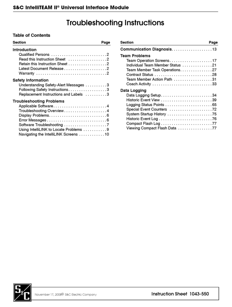
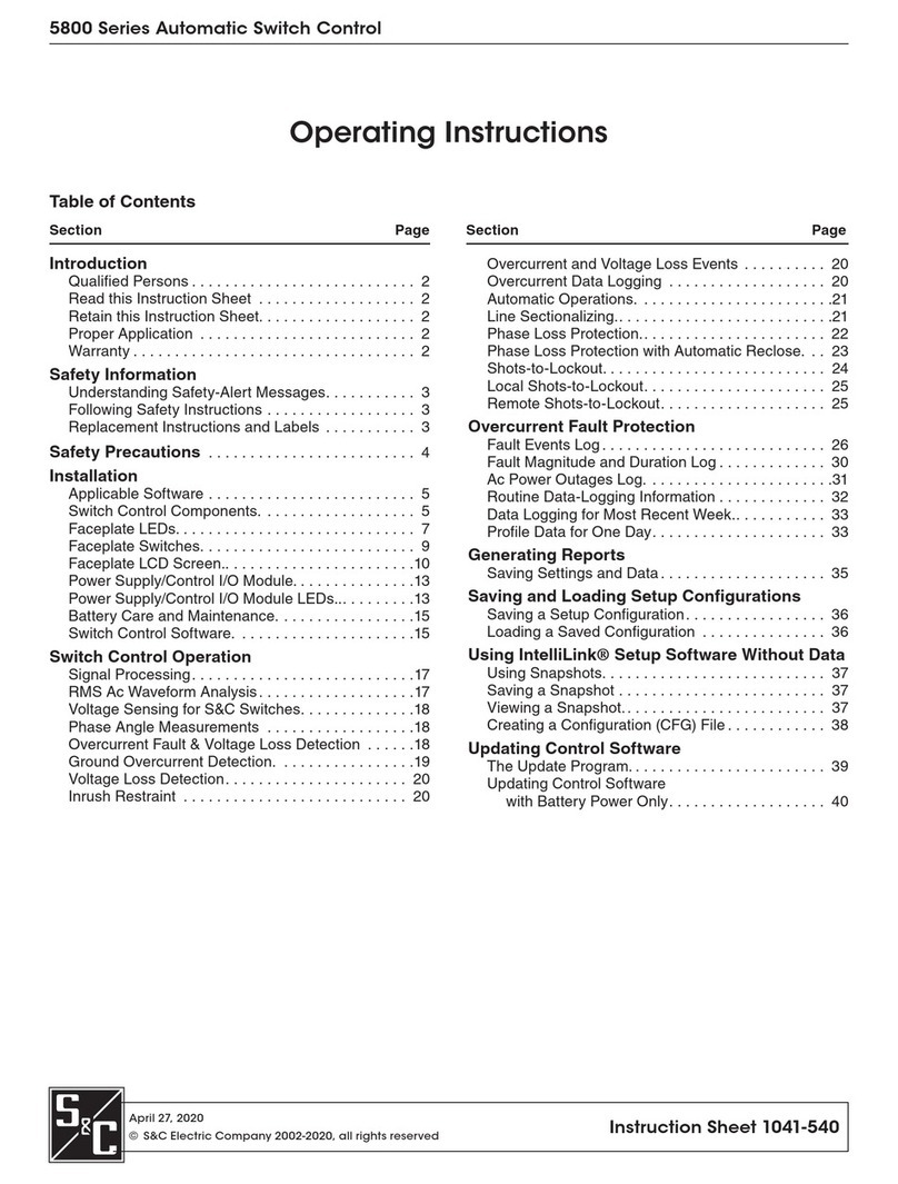
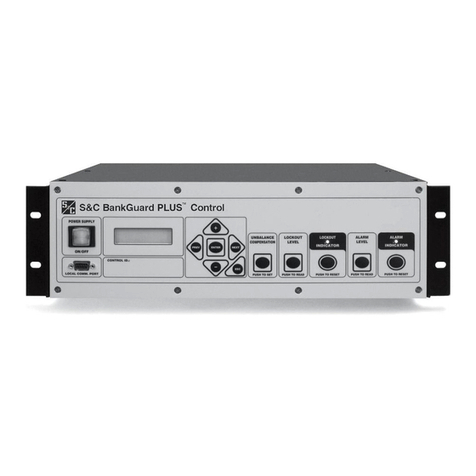
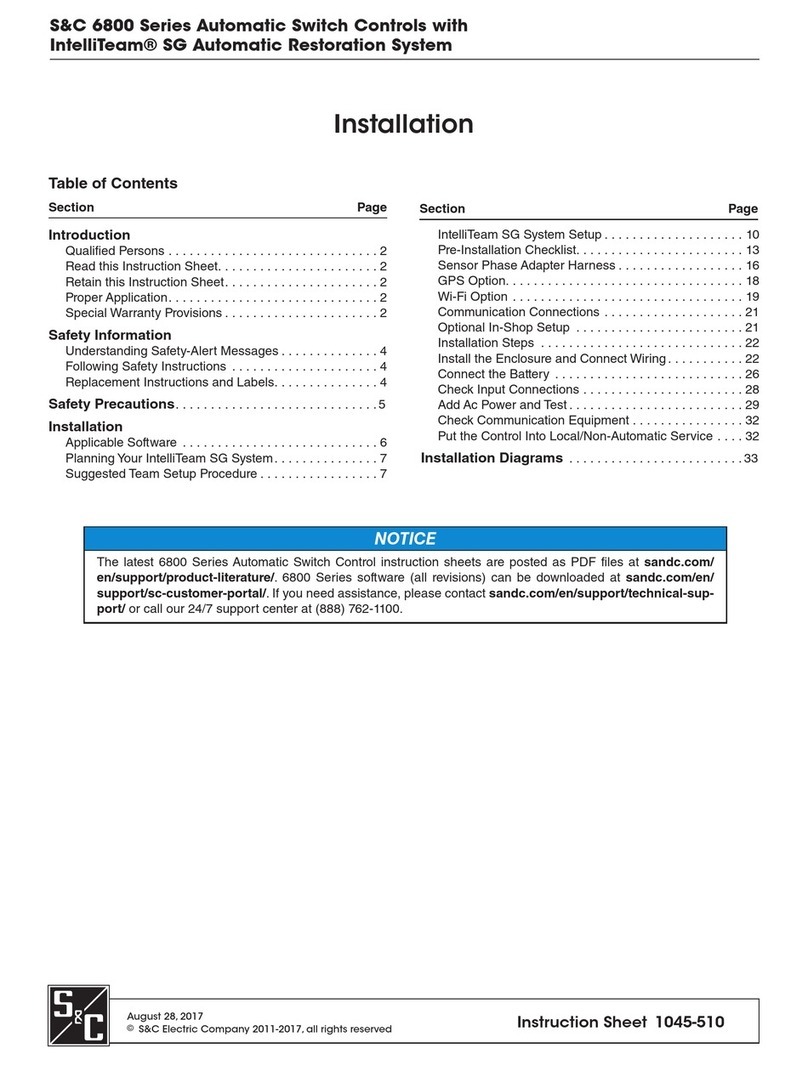
S&C Scada-Mate CCU-SP Maintenance manual

S&C Scada-Mate®Switching Systems Communication and Control Units
Types CCU-SP and CCU-XP Outdoor Distribution (14.4 kV through 34.5 kV)
Instruction Sheet 768-550
© S&C Electric Company 2001-2017, all rights reserved
December 11, 2017
Instructions for Installation, Operation,
Maintenance, and Conguration
Table of Contents
Section Page Section Page
Introduction
Qualified Persons ..............................2
Read this Instruction Sheet ......................2
Retain this Instruction Sheet .....................2
Proper Application .............................2
Warranty .....................................2
Safety Information
Understanding Safety-Alert Messages .............3
Following Safety Instructions .....................3
Replacement Instructions and Labels ..............3
Location of Safety Labels and Tags ...............4
Safety Precautions ............................5
Shipping and Handling
Inspection ....................................6
Packing......................................6
Storage ......................................6
Components ..................................7
Installation
Installing the Communication and Control Unit .......9
Connecting the Control Cable ...................11
Installing and Connecting a User-Supplied
Communication Device ......................13
Connecting an Antenna ........................14
Connecting a Land-Line Interface ................14
Connecting Control Power ......................15
Connecting Remote Terminal Unit Hardware Status
Inputs ....................................16
Testing the Remote Terminal Unit ................16
Placing the Communication and Control Unit into
Operation.................................17
Operation
Loss of Power Alarm ..........................18
Pushbutton Operation .........................18
Remote Operation ............................18
Disconnect Operation. . . . . . . . . . . . . . . . . . . . . . . . . . 19
Emergency Manual Operation ...................20
Maintenance
Periodic Battery and Battery Charger Inspection ....21
Charging Voltage .............................22
Charging the Battery Packs .....................23
Battery Pack Replacement......................24
Specifications
S&C Battery Charger ..........................25
Monobloc Battery Packs in Plastic Outer Case ......25
S&C 5800 Series Automatic Switch Control ........26
Cyclon Battery Packs in Metal Outer Case .........26
Calibration
Calibrating the Voltage- and Current-Sensor Outputs. 27
Alternate Location of Data ......................28
Additional Calibration Factors for Self-Powered Units. 29
For instructions on installation and operation of Scada-Mate
Switches, refer to S&C Instruction Sheet 768-500.

2 S&C Instruction Sheet 768-550
Introduction
WARNING
The equipment covered by this publication must be installed, operated, and
maintainedbyqualifiedpersonswhoareknowledgeableintheinstallation,operation,and
maintenance of overhead electric power distribution equipment along with the
associated hazards. A qualified person is one who is trained and competent in:
• The skills and techniques necessary to distinguish exposed live parts from nonlive
parts of electrical equipment
• The skills and techniques necessary to determine the proper approach distances
corresponding to the voltages to which the qualified person will be exposed
• The proper use of the special precautionary techniques, personal protective
equipment, insulating and shielding materials, and insulated tools for working on or
near exposed energized parts of electrical equipment
These instructions are intended only for such qualified persons. They are not intended
to be a substitute for adequate training and experience in safety procedures for this
type of equipment.
NOTICE
Read this instruction sheet thoroughly and carefully before installing or
operating the communication and control unit. Familiarize yourself with the Safety
Information and Safety Precautions on pages 3 through 5. The latest version of this
publication is available online in PDF format at sandc.com/en/support/
product-literature/.
This instruction sheet is a permanent part of your Scada-Mate Switching System
communication and control unit. Designate a location where you can easily retrieve and
refer to this publication.
WARNING
The equipment in this publication must be selected for a specific application.
The application must be within the ratings furnished for the selected equipment.
The warranty and/or obligations described in S&C’s Price Sheet 150 “Standard Conditions
of SaleImmediate Purchasers in the United States” (or Price Sheet 153, Standard Conditions
of Sale -Immediate Purchasers Outside the United States) plus any special warranty
provisions, as set forth in the applicable product-line specication bulletin, are exclusive.
The remedies provided in the former for breach of these warranties shall constitute the
immediate purchaser’s or end user’s exclusive remedy and a fulllment of the seller’s entire
liability. In no event shall the seller’s liability to the immediate purchaser or end user exceed
the price of the specic product that gives rise to the immediate purchaser’s or end user’s
claim. All other warranties, whether express or implied or arising by operation of law,
course of dealing, usage of trade or otherwise, are excluded. The only warranties are those
stated in Price Sheet 150 (or Price Sheet 153), and THERE ARE NO EXPRESS OR IMPLIED
WARRANTIES OF MERCHANTABILITY OR FITNESS FOR A PARTICULAR PURPOSE.
ANY EXPRESS WARRANTY OR OTHER OBLIGATION PROVIDED IN PRICE SHEET 150
(OR PRICE SHEET 153) IS GRANTED ONLY TO THE IMMEDIATE PURCHASER AND END
USER, AS DEFINED THEREIN. OTHER THAN AN END USER, NO REMOTE PURCHASER
MAY RELY ON ANY AFFIRMATION OF FACT OR PROMISE THAT RELATES TO THE
GOODS DESCRIBED HEREIN, ANY DESCRIPTION THAT RELATES TO THE GOODS,
OR ANY REMEDIAL PROMISE INCLUDED IN PRICE SHEET 150 (or PRICE SHEET 153.)
Qualified Persons
Read this
Instruction Sheet
Retain this
Instruction Sheet
Proper Application
Warranty

S&C Instruction Sheet 768-550 3
Safety Information
Understanding
Safety-Alert Messages
Following
Safety Instructions
Replacement
Instructions and
Labels
Several types of safety-alert messages may appear throughout this instruction sheet and
on labels attached to the communication and control unit. Familiarize yourself with these
types of messages and the importance of these various signal words:
DANGER
“DANGER” identifies the most serious and immediate hazards that will likely result in
serious personal injury or death if instructions, including recommended precautions,
are not followed.
WARNING
“WARNING” identifies hazards or unsafe practices that can result in serious personal
injury or death if instructions, including recommended precautions, are not followed.
CAUTION
“CAUTION” identifies hazards or unsafe practices that can result in minor personal
injury if instructions, including recommended precautions, are not followed.
NOTICE
“NOTICE” identifies important procedures or requirements that can result in product
or property damage if instructions are not followed.
If you do not understand any portion of this instruction sheet and need assistance,
contact your nearest S&C Sales Office or S&C Authorized Distributor. Their
telephone numbers are listed on S&C’s website sandc.com, or call S&C Headquarters
at (773) 338-1000; in Canada, call S&C Electric Canada Ltd. at (416) 249-9171.
NOTICE
Read this instruction sheet thoroughly and
carefully before installing or operating your Scada-
Mate Switching System communication and control
unit.
If you need additional copies of this instruction sheet, contact your nearest S&C Sales Ofce,
S&C Authorized Distributor, S&C Headquarters, or S&C Electric Canada Ltd.
It is important that any missing, damaged, or faded labels on the equipment be replaced
immediately. Replacement labels are available by contacting your nearest S&C Sales Office,
S&C Authorized Distributor, S&C Headquarters, or S&C Electric Canada Ltd.

4 S&C Instruction Sheet 768-550
Safety Information
Location of Safety Labels and Tags
Reorder Information for Safety Information
Location Safety Alert Message Description Part Number
AIMPORTANT Place in operation or charge batteries in this equipment . . . G-6227▲
BIMPORTANT Place in operation or charge batteries in this equipment . . . G-6226▲
CWARNING Electrical Shock—Before energization and at all times when
energized . . . G-6289▲
DWARNING Electrocution Hazard—Failure to follow these instructions can
cause serious injury or death . . . G-6815▲
EWARNING Electrocution Hazard—Failure to follow these instructions can
cause serious injury or death . . . G-6814
▲This part is a tag to be removed and discarded after the control unit is installed and adjusted.
AE
B
D
C

S&C Instruction Sheet 768-550 5
Safety Precautions
DANGER
S&C Scada-Mate Switching Systems contain high voltage. Failure to observe the
precautions below will result in serious personal injury or death.
Some of these precautions may differ from your company’s operating procedures and
rules. Where a discrepancy exists, follow your company’s operating procedures and rules.
1. QUALIFIED PERSONS.Access to switches and
controls must be restricted only to qualified persons.
See “Qualified Persons” on page 2.
2. SAFETY PROCEDURES. Always follow safe operating
procedures and rules.
3. PERSONAL PROTECTIVE EQUIPMENT. Always use
suitable protective equipment, such as rubber gloves,
rubber mats, hard hats, safety glasses, arc-flash
clothing, and fall protection, in accordance with safe
operating procedures and rules.
4. SAFETY LABELS. Do not remove or obscure any of
the “DANGER,” “WARNING,” “CAUTION,” or “NOTICE”
labels and tags. Remove tags ONLY if instructed to do
so.
5. OPERATING MECHANISM AND BASE.The stored-
energy operating mechanism and switch base contain
fast-moving parts that can severely injure fingers. Do
not remove or disassemble the operating mechanism
or remove access panel on the switch base unless
directed to do so by S&C Electric Company.
6. ENERGIZED COMPONENTS.Always consider all
parts live until de-energized, tested, and grounded.
7. GROUNDING. Before energization and at all times
when energized, the switch base and control unit
enclosure must be connected to suitable earth ground
at the pole base in accordance with the S&C instruction
sheet furnished with this device.
The switch base ground must also be connected
to the system neutral. If the system neutral is not
present, proper precautions must be taken to ensure
the local earth ground cannot be severed or removed.
8. LOAD-INTERRUPTER SWITCH POSITION. Always
confirm the Open/Close position of load-interrupter
switches by visually observing the indicator.
Interrupters and terminal pads may be energized from
either terminal.
Interrupters and terminal pads may be energized with
the interrupters in any position.
9. MAINTAINING PROPER CLEARANCE.Always
maintain proper clearance fromenergizedcomponents.

6 S&C Instruction Sheet 768-550
Shipping and Handling
Inspection
Examine the shipment for external evidence of damage as
soon after receipt as possible and preferably before removal
from the carrier’s vehicle. Check the bill of lading to make
sure that all shipping skids, crates, and containers listed are
present.
If there is visible loss and/or damage:
STEP 1. Notify the delivering carrier immediately.
STEP 2. Ask for a carrier inspection.
STEP 3. Note condition of shipment on all copies of the
delivery receipt.
STEP 4. File a claim with the carrier.
If concealed damage is discovered:
STEP 1. Notify the delivering carrier within 15 days of
receipt of shipment.
STEP 2. Ask for a carrier inspection.
STEP 3. File a claim with the carrier.
Also, notify S&C Electric Company in all instances of loss
and/or damage.
Packing
The communication and control unit is packaged and crated
appropriately to avoid damage during shipment. A catalog
drawing and wiring diagram for the communication and
control unit is located in a water-resistant envelope in the
instruction manual holder inside the control unit enclosure.
Similarly, a catalog drawing and wiring diagram for the
selected S&C Scada-Mate Switch is located in a water-
resistant envelope attached to the switch. Study these
drawings carefully and check the parts list to verify all parts
are at hand.
A complete S&C Scada-Mate Switching System includes
the following:
1. Switch
2. Communication and control unit
• Optional remote terminal unit
• Optional communication device
• Stainless steel enclosure
• Miscellaneous parts and pieces
3. Control cable
4. Optional features not assembled to switch
5. Yellow card—sensor data for switch
6. Instruction manual
Storage
If the communication and control unit will not be placed
into service by the date marked on the control, the batteries
will require charging. See the “Charging the Battery Packs”
section on page 25.

S&C Instruction Sheet 768-550 7
Components
CCU-SP—Communication and Control Unit
Self-Powered by S&C Voltage Sensor
See Figures 1 and 2.
User-specified communication device
User-specified remote terminal unit
Provisions for an external control source
include fuses and an isolation transformer
Optional extra dual-battery packs provide
additional power when required for a user-
specified RTU or communication device
Optional auxiliary battery charger float charges
extra battery packs needed for some Remote
Terminal Units and communication devices
Battery charger provides continuous float charge
to battery packs
Switch control includes OPEN/CLOSE
pushbuttons, switch-position indicating lamps,
a disconnect closed and latched indicating lamp, a
LOCAL/REMOTE switch, and an operation counter
Dual battery packs provide power for the
installation
316L stainless steel NEMA 4X enclosure with a
three-point door latch and a padlockable handle
Figure 1. The Type CCU-SP Unit component location.
Figure 2. The Type CCU-SP Unit with the weing-out panel open.

8 S&C Instruction Sheet 768-550
S&C Voltage Sensor Burden Assembly
Battery charger/switch control unit uses unique
high-output battery-management circuitry to provide a
continuous float charge to battery packs. Also includes
an integral switch control that has OPEN/CLOSE push-
buttons, switch-position indicating lamps, a disconnect
closed and latched indicating lamp, aLOCAL/REMOTE
switch, and an operation counter
Dual battery packs provide power for the
installation
316L stainless-steel NEMA 4X enclosure with
three-point door latch and padlockable handle
Components
CCU-XP—Communication and Control Unit
Externally Powered by Ac Source
See Figures 3 and 4.
Provisions for a user-specified communication
device
Provisions for a user-specified remote
terminal unit
Fuses and an isolation transformer for an external
ac source
Standard extra dual-battery packs provide
additional power when required for a user-specified
RTU or communication device
Figure 3. The Type CCU-XP Unit component location.
Figure 4. The Type CCU-XP Unit with the weing-out panel open.

S&C Instruction Sheet 768-550 9
Installation
Installing the Communication and Control
Unit
Before installing the communication and control unit, install
the S&C Scada-Mate Switch in accordance with Instruction
Sheet 768-500, shipped with the switch.
STEP 1. Drill two /-inch diameter holes 9⅜inches apart
in the center of the utility pole and at the desired
height for mounting the communication and control
unit. The communication and control unit should
be mounted at least 10-feet (305 cm) above
ground level to minimize exposure to vandals. See
Figure 5.
The maximum permissible distance between
the lower through-bolt of the switch and the top
through-bolt of the communication and control
unit, when using the standard 35-foot (1067-cm)
control cable, is 28 feet 4 inches (864 cm) for
switches in the upright, vertical, and pole-top
mounting configurations, or 32 feet 6 inches
(991 cm) for switches in the tiered-outboard
mounting configuration.
These dimensions should be increased by 10 feet
(305 cm) when the switch is supplied with optional
45-foot (1372 cm) length control cable (catalog
number suffixes “-C45” or “-G45”). The above
dimensions should be reduced by 10 feet (302 cm)
when the switch is supplied with an optional 25-foot
(762 cm) length control cable (catalog number
suffixes “-C25” or “-G25”).
Figure 5. To minimize exposure to vandals the communication
and control unit should be mounted at least 10 feet (305 cm)
above ground level.
CCU

10 S&C Instruction Sheet 768-550
Installation
STEP 2. Insert two /-inch diameter through-bolts (supplied
by others) in the holes drilled in Step 1. Secure these
bolts loosely with the necessary washers and nuts
so the heads of the bolts project sufciently
(approximately 3 inches (76 mm) from the face of
the pole) to engage the enclosure mounting frame.
For installation with a switch in the vertical
mounting conguration, mount the communiction
and control unit on the face of the pole opposite the
switch to allow space for the cable riser.
STEP 3. Attach an appropriate lifting sling and slowly raise
the sling so it becomes taut. Carefully raise the
control unit to the mounting height and guide it so
the through-bolts projecting from the utility pole
slip into the two keyholes in the enclosure mounting
frame. Lower the enclosure slightly so it bears on
the through-bolts. Fully tighten the bolts and make
sure the washer for each bolt is between the bolt
head and the mounting frame.
STEP 4. Ground the enclosure by solidly connecting one No.
6AWG wire (or wires of equivalent cross-sectional
area) to the ground lug on the back of the enclosure.
See Figure 6. Solidly connect the other end of the
enclosure ground wire to the switch ground wire(s).
Figure 6. The enclosure ground lug is on the pole side.
Ground lug

S&C Instruction Sheet 768-550 11
Installation
Connecting the Control Cable
STEP 5. A shielded control cable is included with the Scada-
Mate Switch for connecting the switch to the
communication and control unit. Remove the
control cable from its shipping carton. The control
cable is provided with multi-pin connector plugs—
male for connecting to the switch and female for
connectingtothecontrolunit.Locatethereceptacle
on the back of the switch base and remove the dust
cover. Remove the sensor shorting blocks from the
receptacle and attach the control cable plug. Secure
the plug with the connector clips. Refer to
Instruction Sheet 768-500. Retain the dust cover
and sensor shorting blocks for future use. See
Figure 7.
STEP 6. Locate the connector plug on the back of the
communication and control unit enclosure, remove
the dust cover, and attach the control cable plug.
Secure the plug with the connector clips. Retain the
dust cover for future use. See Figure 8.
Control cable
Connector clips
Connector
receptacle
Connector plug
Figure 7. Connect the control cable to the switch. (A Scada-Mate
Switch in the upright mounting configuration is shown.)
Connector plug
Connector clips
Control cable
Connector receptacle
Figure 8. Connect the control cable to the communication and
control unit.

12 S&C Instruction Sheet 768-550
Installation
STEP 7. A stainless steel security belt is included with the
communication and control unit for padlocking the
connector. Place the security belt around the
connector, between the connector clips and the
enclosure. Insert a padlock (not furnished) through
the security belt holes. See Figure 9.
STEP 8. Form a drip loop in the control cable where it
attaches to the control unit. Maintain a 9-inch (229-
mm) minimum radius when bending the control
cable at the drip loop and at the switch connection.
Adjust the control cable along the length of the
utility pole and form a coil with any excess cable
(maintaining a 9-inch (229-mm) minimum radius).
Secure the control cable to the utility pole using
suitable guards or clamps.See Figure 10.
Figure 10. Connecting the control cable to the utility pole.
Security belt
Padlock (provided
by others)
Drip loop
(maintain a 9-inch
(229-mm) minimum
radius when bending
the control cable)
Figure 9. Secure the connector at the control unit.
Security belt

S&C Instruction Sheet 768-550 13
Installation
Installing and Connecting a User-Supplied
Communication Device
STEP 9. Mounting provisions are provided inside the
communication and control unit for a user-spec-
ied communication device. Consult your nearest
S&C Sales Ofce for mounting-conguration
availability.
When installing a 12-volt dc communication
device in the field: Connect power to the
communication device by wiring terminals “37”
and “38” on terminal block T4 to the power input
terminals on the communication device. See
Figure 7.
When installing 24-volt dc communication
device in the field: Connect power to the
communication device by wiring terminals “37”
and “40” on terminal block T4 to the power input
terminals on the communication device. See
Figure 11. Figure 11. Connect power to the communication device using the
indicated terminal block.
NOTICE
The battery charger float charge is factory-calibrated to
accommodate the loads installed in the communication
and control unit at the time of shipment. If additional
loads are subsequently added, recalibration of char-
ger output is recommended to ensure optimal battery
life. Please refer to the included S&C Battery Charger
recalibration Procedure RD-3808.
NOTICE
Make sure the communication port on the RTU is
isolated from the power supply. Failure to do so can
result in a short circuit and cause equipment damage.
NOTICE
When the communication device is supplied by
others, use of a surge suppressor between the antenna
and the communication device is recommended to
prevent damage from lightning surges. Contact the
communication device manufacturer for recommended
surge suppressors.

14 S&C Instruction Sheet 768-550
Installation
Connecting an Antenna
STEP 10.When S&C supplied the communication device:
An antenna surge suppressor is included in the
enclosure, as shown in Figure 12. Attach the
antenna cable (not furnished) to the female Type N
connector on the surge suppressor.
When the communication device is supplied
by others: Prepare a weather-tight entrance in the
bottom or on the rear of the enclosure in accordance
with utility practice. Install the appropriate surge
suppressor, wiring, connectors, and entrance ttings
(all supplied by others).
Connecting a Land-Line Interface
STEP 11. Prepare a weather-tight entrance in the bottom or at
the rear of the enclosure, in accordance with utility
practice.
Figure 12. Antenna surge suppressor.
Antenna surge
suppressor

S&C Instruction Sheet 768-550 15
Installation
Figure 13. Connect external ac control power to the fuse block.
Connecting Control Power
CAUTION
Make sure the control cable is grounded before con-
necting user-supplied 120 Vac.
STEP 12.For Type CCU-SP:
The communication and control unit is powered by
the S&C Voltage Sensor on the Scada-Mate Switch.
All control power connections are pre-wired.
External ac control power should not be used to
continuously power the device except when options
“U1” or “U3” are supplied and also in certain custom
designs where adequate surge protection and isola-
tion are provided.
In all other instances, the “external ac” input
on the S&C Battery Charger is for use only when
configuring the remote terminal unit in accordance
with the remote terminal unit instructions. Refer
to the included wiring diagram for connections
if “external ac” is required. Note: On the S&C
Battery Charger, Pins 34 and 35 are for external ac
input. Terminal 34 is the line terminal.
For Type CCU-XP:
The communication and control unit is powered by
user-supplied 120-Vac control power. To connect
control power, attach the line and neutral to the
terminals on the bottom of the fuse block. See
Figure 13. Then, connect the ground wire to the
left side plate. Refer to the wiring diagram for
details. The unit is energized when control power
is connected. Batteries are shipped disconnected
and can be connected when the control unit has
ac power.

16 S&C Instruction Sheet 768-550
Installation
Connecting Remote Terminal Unit Hardware
Status Inputs
NOTICE
S&C status inputs are dry contacts and S&C Control
Outputs are wetted with 24 Vdc.
Note: The control output contact must be maintained for
a minimum of one second to ensure switch operation.
STEP 13.When the RTU is supplied by S&C: All hardware
status inputs are prewired to the remote terminal
unit. No additional load should be connected to
these inputs because they are designed for use with
low-power devices and connecting additional load
may cause damage to components.
When the RTU is supplied by others: Refer to the
included wiring diagrams for status inputs.
Testing the Remote Terminal Unit
STEP 14.After conguring the RTU (if furnished), testing
functionality of the communication and control
unit and the automated switch (if connected to the
communication and control unit via the control
cable) can be accomplished with a personal
computer and suitable user-supplied protocol test
software.
NOTICE
In some computers, the communication port signal
ground is internally connected to the chassis ground
to reduce electromagnetic interference (EMI). If such
a computer is used to test a communication device-
equipped communication and control unit, a ground
loop is created that will short-circuit one of the battery
packs.
To avoid short-circuiting the battery pack in the
event your computer has this internal connection,
temporarily disconnect the power connector of the
communication device. After the communication
and control unit has been tested, reconnect the power
connector to the communication device.
Test the remote terminal unit in accordance with
the manufacturer’s standards.

S&C Instruction Sheet 768-550 17
Installation
Placing the Communication and Control Unit
into Operation
WARNING
Before energizing the switch and at all times when
energized, the Scada-Mate Switch base and control unit
enclosure must be connected to a suitable earth ground
at the base of the pole in accordance with the S&C
instruction sheets furnished. The switch base ground
must also be connected to the system neutral. If the
system neutral is not present, proper precautions
must be taken to make sure the local earth ground
cannot be severed or removed. Failure to observe these
instructions can result in serious personal injury due to
electrical shock.
STEP 15.Energize the automated switch in accordance with
standard operating practices.
For Type CCU-SP:
Conrm that the battery charger input selector
switch is in the Voltage Sensor Source position.
Then, place the battery charger power switch in
the On position and conrm that the POWER LED
display is lit and the CHARGER OVERVOLTAGE and
BATTERY LOW LED displays are not lit.
When the control unit is first powered, the
mechanism on the automated switch may begin
charging the spring if it was not fully charged. The
mechanism will take approximately 3 seconds to
charge after each operation. See Figure 14.
For Type CCU-XP:
When ac power is connected to the control unit, it
will be energized.
When the control unit is first powered, the
mechanism on the automated switch may begin
charging the spring if it was not fully charged. The
mechanism will take approximately 3 seconds to
charge after each operation. See Figure 14.
For a vertical configuration switch, or if the
“H” option was specified, it may take 30 seconds
to one minute for the mechanism to charge after
each operation.
STEP 16.If the remote terminal unit is provided with a
power switch, verify that the switch is in the On
position.
Figure 14. The switch mechanism.
Switch mechanism

18 S&C Instruction Sheet 768-550
Loss of Power Alarm
For CCU-SP:
Enable the Loss of Ac Source alarm. The battery charger
Loss of Ac Source alarm is shipped in the Disabled state.
To enable it, remove the battery charger cover and nd the
jumper near the pins labeled “w.” Move the jumper from the
right side to the left side.
For CCU-XP:
The battery charger/switch control combination unit has
a Charger Off alarm shipped in the Enabled state. Just
connect control power.
Figure 15. The Type CCU-SP control.
Figure 16. The Type CCU-XP control.
Local/remote
switch
Open/closed
switch
LOCAL/REMOTE
switch
OPEN and CLOSE
pushbuttons
Pushbutton Operation
Place the LOCAL/REMOTE switch inside the communication
and control unit in the Local mode. See Figures 15 and 16.
Then, press the OPEN or CLOSE pushbutton as required.
The interrupter OPEN/CLOSED indicator on the end of the
switch base indicates interrupter position. The target with
an “O” indicates the interrupters are open; the target with a
“C” indicates the interrupters are closed. The indicator does
not show the status of the disconnect. Refer to Instruction
Sheet 768-500, “S&C Scada-Mate Switching Systems: Outdoor
Distribution (14.4 kV through 34.5 kV).” See Figure 17.
Remote Operation
Place the LOCAL/REMOTE switch inside the
communication and control unit in the Remote mode. See
Figures 15 and 16.
Operation can only occur now by remote supervisory
control or manually by using a hookstick.
Operation
Figure 17. A Scada-Mate Switch shown in the Open position.
Interrupter position
indicator

S&C Instruction Sheet 768-550 19
Operation
Disconnect Operation
An integral hookstick-operated, three-pole disconnect is built
into every Scada-Mate Switching System to provide visible
air-gap isolation of switched-open circuits.
Follow these steps to open the disconnect:
STEP 1. Place the LOCAL/REMOTE switch inside the
communication and control unit in Local mode.
Operation can only occur now by local control or
manually by using a hookstick.
STEP 2. Open the interrupter contacts by pressing the
OPEN pushbutton.
STEP 3. Open the disconnect by pulling on the disconnect
operating lever with a suitable hookstick. The
disconnect will not open unless the interrupter
contacts are in the Open position.
Refer to Instruction Sheet 768-500, “S&C Scada-
Mate Switching Systems: Outdoor Distribution
(14.4 kV through 34.5 kV).”
STEP 4. Provision for tagging the three-pole
disconnect are provided when the disconnect is in
the open position. Refer to Instruction Sheet 768-
500, “S&C Scada-Mate Switching Systems: Outdoor
Distribution (14.4 kV through 34.5 kV).”
Note: For a Type CCU-SP, the DISCONNECT-NOT-LATCHED
indicator is lit when the disconnect is not fully closed. See
Figure 18. For a Type CCU-XP, the VISUAL-BREAK indicator
is lit when the disconnect is not fully closed. See Figure 19.
Figure 19. TheType CCU-XP VISUAL BREAK indicator is lit when
the disconnect is not fully closed.
Figure 18.TheType CCU-SP DISCONNECT NOT LATCHED indica-
tor is lit when the disconnect is not fully closed.
Visual break
indicator

20 S&C Instruction Sheet 768-550
Operation
STEP 5. To close the disconnect: pull down on the dis-
connect operating lever with a hookstick. See
Figure 20. Closing the disconnect does not close the
interrupter contacts. The switch must be closed
electrically or by hookstick to close the interrupter
contacts.
Note: The switch must be open before opening the discon-
nect, except for vertical-conguration switches or if the “H”
option was specied.
DANGER
The interrupters and terminal pads of a Scada-Mate
Switch may be energized with the interrupters in any
position. Before inspecting, servicing, or repairing this
switch or working on the conductors on either side of
the switch, test for voltage using proper high-voltage
test equipment. Then install suitable grounding equip-
ment. Failure to observe these precautions may result
in serious injury or death.
Emergency Manual Operation
In the event of electrical power loss, a standard or extendible
hookstick is used to open and close the interrupters. When the
spring is fully discharged, pull on the operating mechanism
pull-ring with the hookstick seven to nine times to effect a
change of state. If the spring is partially charged, just a single
pull will change the interrupter position. Refer to Figure 21.
Figure 21. Manual operation using a hookstick. A Scada-Mate
CX™ Switch is shown.
Figure 20. Pull down on the disconnect operating lever with the
hookstick
This manual suits for next models
1
Table of contents
Other S&C Control Unit manuals
Popular Control Unit manuals by other brands

Intellijel
Intellijel Duatt 1U user manual

Kohler
Kohler Rite-Temp K-8300-PX quick start guide

NEW ENERGY
NEW ENERGY PV installation instructions

Phaesun
Phaesun solar manual

Texas Instruments
Texas Instruments BoosterPack Educational Plug-in Module Mark II... user guide

TLV
TLV Cospect MC-COS-3 instruction manual

ProSoft Technology
ProSoft Technology MVI69E-LDM-MQTT quick start guide

Cobra
Cobra 2980 manual

Bartec
Bartec 17-A1Z0-0005 Installation instruction

Innovative Electronics
Innovative Electronics EMS 30 A H-Bridge quick start

Crosswater
Crosswater SE350DC installation instructions

Phason
Phason iWire Flex Radio installation guide