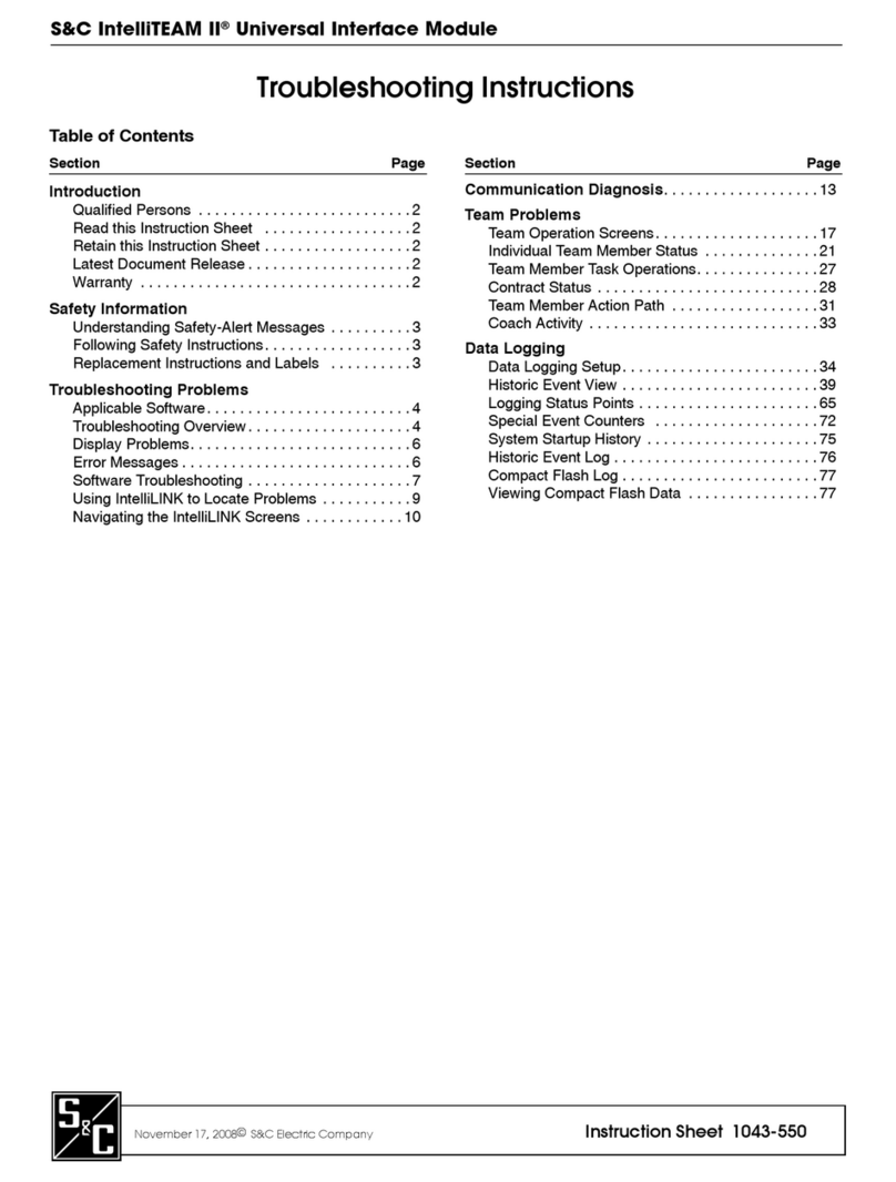
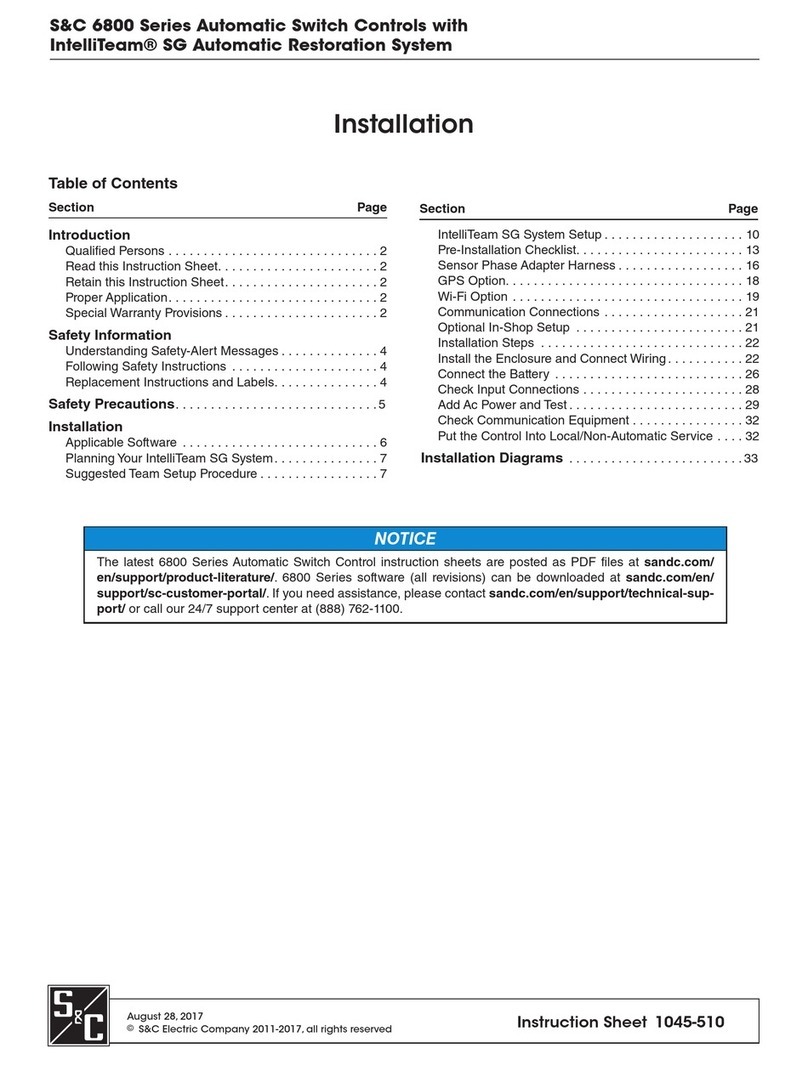
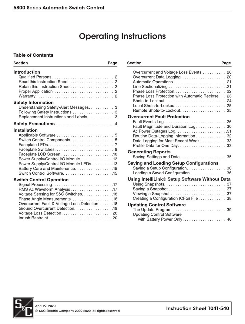
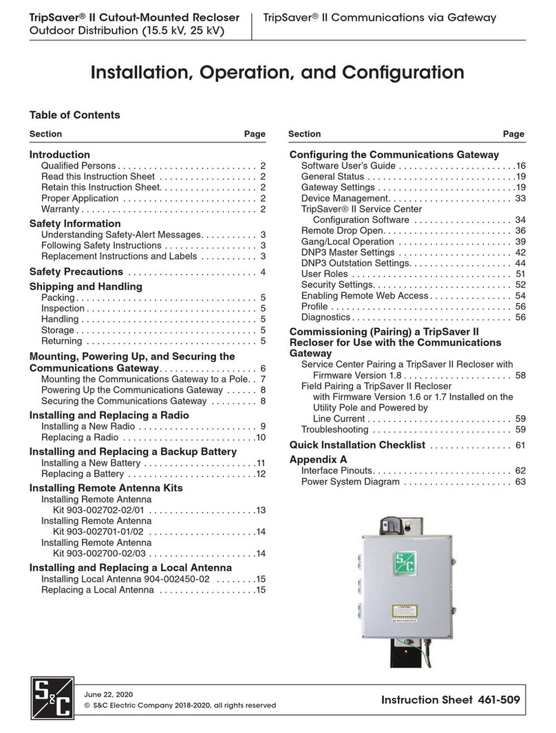
S&C BankGuard PLUS User manual

1011-540 5-17-04
BankGuard PLUS™
Control
Operation Instructions
S&C Electric Company
6601 North Ridge Blvd.
Chicago, Illinois 60626 USA

BankGuard PLUS S&C Electric Company
Control Proprietary Information
2 Operation 1011-540 5-17-04
Instruction Sheets Include:
Product Description 1011-500 explains important product features.
Installation 1011-510 describes how to install and connect the
BankGuard PLUS Control.
Setup 1011-530 describes how to use the Setup software to
configure the BankGuard PLUS Control, check the
present settings, and view real-time data.
Operations 1011-540 describes how to view historical data, how
to generate reports, and how to update the Control
software. This instruction sheet also explains how
the BankGuard PLUS Control works during normal
operation.
Troubleshooting 1011-550 describes how to diagnose and correct
various BankGuard PLUS Control problems.
Latest Release of This Document
The latest release of this instruction sheet is available online at www.sandc.com.
Select: Support/ Product Support Documents. Documents are posted in PDF format.
Safety Information
WARNING
The equipment covered by this publication must be installed, operated, and maintained
by qualified persons who are knowledgeable in the installation, operation, and
maintenance of overhead electric power distribution equipment along with the
associated hazards. A qualified person is one who is trained and competent in:
zThe skills and techniques necessary to distinguish exposed live parts from non-live
parts of electrical equipment.
zThe skills and techniques necessary to determine the proper approach distances
corresponding to the voltages to which the qualified person will be exposed.
zThe proper use of the special precautionary techniques, personal protective
equipment, insulating and shielding materials, and insulated tools for working on or
near exposed energized parts of electrical equipment.
These instructions are intended only for such qualified persons. They are not intended
to be a substitute for adequate training and experience in safety procedures for this type
of equipment.

1011-540 5-17-04 Operation 3
S&C Electric Company BankGuard PLUS
Proprietary Information Control
Read this Instruction Sheet
Thoroughly and carefully read this instruction sheet before programming, operating, or
maintaining your S&C BankGuard PLUS Control. Familiarize yourself with “SAFETY
INFORMATION” on pages 3 through 5.
Retain this Instruction Sheet
This instruction sheet is a permanent part of your BankGuard PLUS Control. Designate a
location where you can easily retrieve and refer to this publication.
Warranty
The standard warranty contained in S&C’s standard conditions of sale, as set forth in Price
Sheet 150, is applicable to the BankGuard PLUS Control.
Understanding Safety-Alert Messages
There are several types of safety-alert messages which may appear throughout this
instruction sheet as well as on labels attached to the BankGuard PLUS Control.
Familiarize yourself with these types of messages and the importance of the various signal
words, as explained below.
DANGER
WARNING
CAUTION
“DANGER” identifies the most serious and immediate hazards which will likely result
in serious personal injury or death if instructions, including recommended precautions,
are not followed.
“WARNING” identifies hazards or unsafe practices which can result in serious personal
injury or death if instructions, including recommended precautions, are not followed.
“CAUTION” identifies hazards or unsafe practices which can result in minor personal
injury or product or property damage if instructions, including recommended
precautions, are not followed.

BankGuard PLUS S&C Electric Company
Control Proprietary Information
4 Operation 1011-540 5-17-04
NOTICE
Following Safety Instructions
If you do not understand any portion of this instruction sheet and need assistance, contact
your nearest S&C Sales Office or call S&C Headquarters at (773) 338-1000, Monday
through Friday between 8:30 AM and 5:00 PM Central Standard Time. (In Canada, call
S&C Electric Canada Ltd. at (416) 249-9171.)
NOTICE
Replacement Instructions and Labels
If you need additional copies of this instruction sheet, contact your nearest S&C Sales
Office, S&C Headquarters, or S&C Electric Canada Ltd.
It is important that any missing, damaged, or faded labels on the equipment be replaced
immediately. Replacement labels are available by contacting your nearest S&C Sales
Office, S&C Headquarters, or S&C Electric Canada Ltd.
Instruction Sheet Contents
Introduction ..................................................................................................................... 5
Applicable Software........................................................................................................ 5
Control Device Hardware and Software ......................................................................... 6
IntelliLINK Software ................................................................................................. 7
SCADA Communications Equipment ............................................................................ 8
Control Device Operations.............................................................................................. 9
Overvoltage Protection for Capacitor Banks .................................................................. 9
Protection for Reactors.................................................................................................... 9
Automatic Control Features .......................................................................................... 10
Ungrounded and Grounded Wye Shunt Capacitor Banks............................................. 11
Ungrounded Wye Shunt Reactors ................................................................................. 15
Signal Processing .......................................................................................................... 17
Generating Reports........................................................................................................ 21
Saving and Loading a Setup Configuration .................................................................. 22
Viewing IntelliLINK Software Without Data ............................................................... 23
Using Snapshots (VM Files) ......................................................................................... 24
Updating the Control Device Software ......................................................................... 26
“NOTICE” identifies important procedures or requirements that, if not followed, can
result in product or property damage if instructions are not followed.
Thoroughly and carefully read this instruction sheet before programming and operating
your S&C BankGuard PLUS Control.

1011-540 5-17-04 Operation 5
S&C Electric Company BankGuard PLUS
Proprietary Information Control
Introduction
This instruction sheet provides information related to daily operation of the BankGuard
PLUS Automatic Control Device, including:
zControl device hardware and software components (page 6)
zControl device features (page 9)
zGenerating reports (page 21)
zSaving and loading setup configurations (page 22)
zViewing the IntelliLINK software without data (page 23)
zCreating and using snapshots (VM files) (page 24)
zUpdating the Control Device software (page 26)
Applicable Software
This instruction sheet was prepared for use with software UPPD105S or later releases.
You can find the release date on the Setup disk label. For questions regarding the
applicability of information in this instruction sheet to future software releases, please
contact S&C.

BankGuard PLUS S&C Electric Company
Control Proprietary Information
6 Operation 1011-540 5-17-04
Control Device Hardware & Software
This section describes various control device components. The following section,
Overview of Control Device Operations, explains how these components work together to
monitor and manage capacitor bank/reactor operation.
The Control Device Hardware Components and Faceplate
Figure 1 shows hardware components of the control device that you may need to access
during regular operation and troubleshooting.
The BankGuard PLUS faceplate includes LEDs and buttons which allow you to monitor
the capacitor bank/reactor and the control device. It also includes a liquid crystal display
and buttons for scrolling and selecting data.
Figure 1
Location of BankGuard Plus Control Device Components
Local communications port – The control device has a port on its faceplate for
local communications. If your control device includes communications equipment,
it will usually be connected to the SCADA COMM PORT on the back.
Terminal strips – Every BankGuard PLUS control device includes two numbered
terminal strips for connecting to the external control wiring. Their configuration is
shown in the Installation Instruction Sheet 1011-510.
Terminal Strips
(on back)
Power Supply
ON/OFF Button
Faceplate LCD
and Keypad
Faceplate Local
Communications
Port

1011-540 5-17-04 Operation 7
S&C Electric Company BankGuard PLUS
Proprietary Information Control
Control Device Software
S&C controls and devices are entirely software-driven. Each control device is shipped
with Control Device software and IntelliLINK®software.
Control Device Software
The Control Device software is preloaded into the control device in the factory. This
software manages the minute-by-minute functioning of the control device. It continually
monitors:
zvoltage on the feeder
zincoming SCADA commands
zthe state of the faceplate LEDs and buttons
zthe internal control device clock/calendar
zthe software setpoint values
zvarious other setpoints and data values as needed
Based on this information, the Control Device software decides how to respond to a
change in voltage, a command from the faceplate or SCADA master station, and other
conditions.
The Control Device software and the setpoint values are all stored in non-volatile control
device memory. This memory survives power interruptions. The memory chip is a battery-
backed RAM with 20 year expected life in the powered state (10 year shelf life without
power).
IntelliLINK Software
The IntelliLINK software is supplied on the Setup disk and runs on IBM/PC-compatible
computers. This software allows you to communicate with the Control Device software
while you are at the control device site. Using the IntelliLINK software, you can:
zEnter installation-dependent operating parameters (setpoints), such as a network
address, a voltage lockout level, etc.
zMonitor real-time data, such as the present line-to-ground voltage.
zTransfer all configuration, operating, and historical data from the control device to
a “report” file on your computer.
zDownload new Control Device software into the control device.
zTroubleshoot assorted types of control device installation problems.

BankGuard PLUS S&C Electric Company
Control Proprietary Information
8 Operation 1011-540 5-17-04
SCADA Communications Equipment
Most types of communications equipment can be mounted near the control device. This
eliminates clutter and provides a higher level of reliability for the overall installation.
DNP 3.0 is the standard protocol for the BAnkGuard PLUS control device; other protocol
options are also available.
For more details, see the appropriate Communications Points List, or contact S&C.

1011-540 5-17-04 Operation 9
S&C Electric Company BankGuard PLUS
Proprietary Information Control
Overview of Control Device Operations
This section explains how the control device components work together to control the
capacitor bank or reactor.
Overvoltage Protection for Capacitor Banks
Medium to large wye-connected shunt capacitor banks commonly use twofold protection
against short circuits:
zIndividual capacitor units are protected by fuse links that clear internal faults,
reducing the probability of case ruptures.
zThe system is protected against major faults by the bank protective device, such as
power fuses or an S&C Circuit-Switcher.
But when a fuse link operates to isolate a failed capacitor unit, the voltage across
remaining units in the same series group increases. This increased voltage can overstress
and shorten the life of the other good capacitor units in the group. As subsequent units fail,
their isolation leads to still further voltage increases on remaining units. The result is an
accelerating cascade of overvoltages that destroys good capacitor units.
This phenomenon is addressed in IEEE Standard 18-1992, “IEEE Standard for Shunt
Power Capacitors.” The standard specifies a curve (Figure 2) which indicates the
permissible capacitor unit operating time at varying per-unit multiples of the capacitor
nameplate voltage rating. This curve applies for up to 300 applications of power-
frequency overvoltages of the magnitude and duration shown. (The standard further
requires that capacitors be capable of continuous operation to at least 110% of the rated
voltage, including harmonics. Most capacitor manufacturers publish similar data, which
may permit higher working voltages.) When the voltage applied to the surviving capacitor
units exceeds the manufacturer’s maximum recommended working voltage (or in the
absence of a recommendation, the IEEE standard), the entire bank should be removed
from service.
Thus, large-sized capacitor banks need a third form of protection: a control device that is
sensitive enough to detect the isolation of the first failed unit in a capacitor bank, but
sophisticated enough to disregard system and inherent bank imbalances, spurious
transients, and harmonics. Also, the ability to alarm upon isolation of that capacitor unit
lets the user replace it before additional failures occur.
Protection for Reactors
When a developing turn-to-turn fault occurs in any phase winding, the ungrounded, wye-
connected shunt reactor is protected from further damage by automatic switching initiated
by the S&C BankGuard PLUS Automatic Control Device. The control device isolates and
locks out the entire shunt reactor when a predetermined neutral-to-ground voltage is
exceeded.

BankGuard PLUS S&C Electric Company
Control Proprietary Information
10 Operation 1011-540 5-17-04
Figure 2
Capacitor Unit Power Frequency Overvoltage versus Time
(IEEE Standard 18-1992)
Automatic Control Features
The BankGuard PLUS control device includes all the automatic features described in this
section.
Bank/Reactor Lockout and Alarm
The lockout logic includes a user-selectable time delay (0.2 to 30 second). The time
delay insures that the fuse for the failing capacitor unit operates before the control
device locks out the bank. This lets you readily locate the failed capacitor unit.
The BankGuard PLUS Automatic Control Device includes a standard alarm function,
which provides an alarm signal (after a time delay) upon the loss of fewer capacitor
units than that corresponding to the lockout level setting. For many capacitor banks it
is practical to activate the alarm at the loss of a single capacitor unit. This is a decided
advantage since replacement of the failed capacitor unit can be accomplished at a
convenient, planned time, instead of on an urgent basis during a lockout resulting from
Voltage on Capacitor Unit,
Per Unit of Nameplate Voltage Rating
Time, seconds

1011-540 5-17-04 Operation 11
S&C Electric Company BankGuard PLUS
Proprietary Information Control
subsequent failure of capacitor units. If desired, the alarm function can respond to loss
of control power to the BankGuard PLUS control device and set an alarm.
Alarms and lockouts are latched, and maintained across a software reset. They remain
active until the ALARM INDICATOR RESET button or a SCADA command resets
them.
Gross Overvoltage
If a flashover of series groups within the capacitor bank or a failure of an entire reactor
phase occurs, the gross overvoltage logic lets the control device react more quickly
than the normal lockout process. This logic is activated, after a field adjustable time
delay of 0.2 to 5 seconds, by such faults producing a capacitor bank neutral-to-ground
voltage in excess of an adjustable level of 1000 to 5000 volts.
The BankGuard PLUS incorporates a digital input which is actuated through a contact
of the capacitor bank switch-operator auxiliary switch. This digital input prevents
nuisance operation of the BankGuard PLUS alarm or lockout functions resulting from
neutral-to-ground voltages of several kilovolts being induced during periods when the
capacitor bank has been routinely de-energized.
Unbalance Compensation
In larger capacitor banks, extraneous voltages can introduce significant errors in – or
even overpower – the voltage signal created by the loss of individual capacitor units.
For example, a fixed error voltage may be present due to inherent capacitor bank
imbalances from manufacturing-tolerance variations among individual capacitor units,
or due to system voltage imbalances from non-transposition of overhead lines. A
variable error voltage may also be present due to a system load imbalance from
changing load conditions. (This error voltage is usually only significant in very large,
transmission-voltage-level capacitor banks.) Such error voltage can cause false
operations that lock out the capacitor bank/reactor, or cause no operation when one is
necessary.
The unbalance compensation feature (with the addition of station-bus voltage monitoring
devices on ungrounded capacitor banks/reactors) lets the control device detect and
compensate for the error voltage.
Ungrounded and Grounded Wye Shunt Capacitor Banks
The BankGuard PLUS Automatic Control Device provides protection of ungrounded
(Figure 3) and grounded (Figure 4) wye-connected shunt capacitor banks. As individual
capacitor units in a series group are isolated from the bank by their respective fuses, the
control device automatically protects the surviving capacitor units in the group from
cascading voltage overstress. The control device locks out the entire bank when the
neutral-to-ground voltage exceeds the calculated level. (See the Setup Instruction Sheet

BankGuard PLUS S&C Electric Company
Control Proprietary Information
12 Operation 1011-540 5-17-04
1011-530 for more details.) In general, you should enable the unbalance compensation
feature if the magnitude of the error voltage caused by system voltage imbalances and/or
inherent capacitor bank imbalances approaches 50% of the value of the neutral-to-ground
voltage calculated for one isolated capacitor unit.
Figure 3
System Diagram of BankGuard PLUS Control Device
for Ungrounded Wye-connected Capacitor Banks
Figure 4
System Diagram of BankGuard PLUS Control Device
for Grounded Wye-connected Capacitor Banks

1011-540 5-17-04 Operation 13
S&C Electric Company BankGuard PLUS
Proprietary Information Control
For ungrounded wye banks, the control device uses an analog input and digital voltmeter
to detect the capacitor bank neutral-to-ground voltage, as monitored by an S&C 15-Volt-
Ampere Potential Device. A digital filter attenuates harmonics and noise.
•When the Unbalance Compensation feature is disabled, the magnitude of the real-time
neutral-to-ground voltage is compared with the “Gross Over Voltage Level,” “Lockout
Level,” and “Alarm Level” setpoint values, if enabled. Capacitor unit failures will cause
the real-time neutral-to-ground voltage magnitude to change. If the real-time neutral-to-
ground voltage magnitude exceeds a setpoint value continuously for a time greater than
the applicable time delay setpoint value, the appropriage control action is taken. The
control will lock the bank out if the “Gross Over Voltage Level” or the “Lockout Level”
setpoint value is exceeded. The control will issue an alarm if the “Alarm Level” setpoint
value is exceeded.
•In addition to the neutral-to-ground potential device, one 30-Volt-Ampere S&C
Potential Device is required to be installed on any one of the line phases to obtain a
reference angle when the Unbalance Compensation feature is set to “Cap Only.” During
the setup of the Unbalance Compensation feature, a neutral-to-ground voltage magnitude
sample and a reference angle (Aref) sample are used to obtain and store an approximate
magnitude correction value (see Signal Processing below for an explanation of how the
value is calculated). Setup of the Unbalance Compensation feature should be
accomplished during a time when any voltage unbalances caused by the loads are
minimal. During each control cycle, the stored approximate magnitude correction value is
subtracted from the real-time neutral-to-ground voltage magnitude to obtain a
compensated neutral-to ground voltage magnitude. Capacitor unit failures will cause the
real-time neutral-to-ground voltage magnitude to change and, therefore, change the
compensated neutral-to-ground voltage magnitude. The control compares the
compensated neutral-to-ground voltage magnitude with the “Gross Over Voltage Level,”
“Lockout Level,” and “Alarm Level” setpoint values, if enabled. If the compensated
neutral-to-ground magnitude exceeds a setpoint value continuously for a time greater than
the applicable time delay setpoint value, the appropriate control action is taken. The
control will lockout the bank if the “Gross Over Voltage Level” or the “Lockout Level”
setpoint value is exceeded. Or issue an alarm if the “Alarm Level” setpoint value is
exceeded. The “Cap Only” value is generally selected when the voltage variations
between the line phases are expected to be negligible in comparison to the neutral-to-
ground voltage changes resulting from the loss of capacitor units.
•In addition to the neutral-to-ground potential device, three S&C 30-Volt-Ampere
Potential Devices are required to be installed on each line pahse when the “Unbalance
Compensation” feature is set to “Cap/Line.” The control uses the three potential devices to
obtain the sum of the line voltages magnitude and a reference angle. Since the sum is
obtained from all the line voltages, compensation for fixed system imbalances is provided.
During the setup of the unbalance compensation feature, a neutral-to-ground voltage
magnitude sample, a sum of the line voltages sample and the reference angle are used to
calculate and store a magnitude correction value (see Signal Processing below for an

BankGuard PLUS S&C Electric Company
Control Proprietary Information
14 Operation 1011-540 5-17-04
explanation of how the value is calculated). During each control cycle, the stored
magnitude correction factor is subtracted from the real-time neutral-to-ground magnitude
to obtain a compensated neutral-to-ground voltage magnitude. Capacitor unit failures will
cause the real-time line-to-neutral voltage to change and, therefore, change the
compensated neutral-to-ground voltage magnitude.
The control compares the compensated neutral-to-ground voltage magnitude to the “Gross
Over Voltage Level,” “Lockout Level,” and “Alarm Level” setpoint values, if enabled. If
the compensated neutral-to-ground voltage magnitude exceeds a setpoint value
continuously for a time greater than the applicable time delay setpoint value, the
appropriate control action is taken. The control will lock out the bank if the “Gross Over
Voltage Level” or the “Lockout Level” setpoint values are exceeded. The control will
issue an alarm if the “Alarm Level” setpoint value is exceeded.
For grounded wye banks, the control device uses tap-voltage calibration logic. This logic
develops the sum of the intermediate tap-point voltages on the 3 phase legs, as monitored
by the S&C 30-Volt-Ampere Potential Devices. A digital filter attenuates harmonics and
noise.
•When the Unbalance Compensation feature is disabled, the magnitude of the sum of the
intermediate tap-point-to-neutral voltages is compared (in percent) with the “Gross Over
Voltage Level,” “Lockout Level,” and “Alarm Level” setpoint values, if enabled.
Capacitor unit failures will cause the magnitude of the sum of the intermediate tap-point-
to-neutral voltages to change. If the real-time magnitude of the sum exceeds a setpoint
value continuously for a time greater than the applicable time delay setpoint value, the
appropriate control action is taken. The Control will lock the bank out if the “Gross Over
Voltage Level” or the “Lockout Level” setpoint value is exceeded. The control will issue
an alarm if the “Alarm Level” setpoint value is exceeded.
•In addition to the three 30-Volt-Ampere Potential Devices, one 30-Volt-Ampere S&C
Potential Device is required to be installed on any one of the line phases to obtain a
reference angle when the Unbalance Compensation feature setpoint value is set to “Cap
Only”. During setup of the Unbalance Compensation feature, a sample of the magnitude
of the sum of the intermediate tap-point-to-neutral voltages and a reference angle sample
are used to obtain and store an approximate magnitude correction value (See Signal
Processing below for an explanation of how the value is calculated). Setup of the
Unbalance Compensation feature should be accomplished during a time when any voltage
unbalances caused by the loads are minimal. During each control cycle, the stored
approximate magnitude correction value is subtracted from the magnitude of the real-time
intermediate tap-point-to-neutral voltages sum. Capacitor unit failures will cause the
magnitude of the real-time tap-point-to-neutral voltages sum to change, and therefore,
change the magnitude of the compensated tap-point-to-neutral voltages sum. The control
compares the compensated intermediate tap-point-to-neutral voltages sum magnitude with
the “Gross Over Voltage Level,” “Lockout Level,” and “alarm Level” setpoint values, if
enabled. If the compensated intermediate tap-point-to-neutral magnitude exceeds a
setpoint value continuously for a time greater than the applicable time delay setpoint

1011-540 5-17-04 Operation 15
S&C Electric Company BankGuard PLUS
Proprietary Information Control
value, the appropriate control action is taken. The control will lockout the bank if the
“Gross Over Voltage Level” or the “Lockout Level” setpoint value is exceeded. Or issue
an alarm if the “Alarm Level” setpoint value is exceeded.
Ungrounded Wye Shunt Reactors
The BankGuard PLUS Automatic Control Device provides protection of ungrounded,
wye-connected shunt reactors (Figure 5), either 3-phase reactors or 3-phase banks of
single-phase reactors. The control device detects turn-to-turn faults in the windings of
these shunt reactors, the most common mode of reactor failure. When a developing turn-
to-turn fault occurs in any phase winding, the shunt reactor is protected from further
damage by automatic switching provided by the control device. The control device locks
out the entire shunt reactor when the neutral-to-ground voltage exceeds the calculated
level. (See the Setup Instruction Sheet 1011-530 for more details.) In general, you should
enable the unbalance compensation feature if the magnitude of the calculated error voltage
caused by inherent reactor unbalance resulting from manufacturing-tolerance variations
among the phase windings approaches 50% of the desired lockout-level setting.
For ungrounded, wye-connected shunt reactors, the control device uses an analog input
and digital voltmeter to detect the reactor neutral-to-ground voltage, as monitored by an
S&C 15-Volt-Ampere Potential Device. A digital filter attenuates harmonics and noise.
When the Unbalance Compensation feature is disabled, the magnitude of the real-time
neutral-to-ground voltage is compared with the “Gross Over Voltage Level”, “Lockout
Level”, and “Alarm Level” setpoint values, if enabled. Reactor-turn failures will cause the
real-time neutral-to-ground voltage magnitude to change. If the real-time neutral-to-
ground voltage magnitude exceeds a setpoint value continuously for a time greater than
the applicable time delay setpoint value, the appropriate control action is taken. The
control will lock the reactor out if the “Gross Over Voltage Level” or the “Lockout Level”
setpoint value is exceeded. The control will issue an alarm if the “Alarm Level” setpoint
value is exceeded.
In addition to the neutral-to-ground potential device, one 30-Volt-Ampere S&C Potential
Device is required to be installed on any one of the line phases to obtain a reference angle
when the Unbalance Compensation feature is set to “Reactor” only. During the setup of
the Unbalance Compensation feature, a neutral-to-ground voltage magnitude sample and a
reference angle (Aref) sample are used to obtain and store an approximate magnitude
correction value (see Signal Processing below for an explanation of how the value is
calculated). Setup of the Unbalance Compensation feature should be accomplished during
a time when any voltage unbalances caused by the loads are minimal. During each control
cycle, the stored, approximate magnitude correction value is subtracted from the real-time
neutral-to-ground voltage magnitude to obtain a compensated neutral-to-ground voltage
magnitude. Reactor -turn failures will cause the real-time neutral-to-ground voltage
magnitude to change and, therefore, change the compensated neutral-to-ground voltage
magnitude. The control compares the compensated neutral-to-ground voltage magnitude
with the “Gross Over Voltage Level”, “Lockout Level”, and “Alarm Level setpoint values,
if enabled. If the compensated neutral-to-ground magnitude exceeds a setpoint value

BankGuard PLUS S&C Electric Company
Control Proprietary Information
16 Operation 1011-540 5-17-04
continuously for a time greater than the applicable time delay setpoint value, the
appropriate control action is taken. The control will lockout the bank if the “Gross Over
Voltage Level” or the “Lockout Level” setpoint value is exceeded, or issue an alarm if the
“Alarm Level” setpoint value is exceeded. The “Reactor Only” value is generally selected
when the voltage variations between the line phases are expected to be negligible in
comparison to the neutral-to-ground voltage changes resulting from the loss of reactor
turns.
In addition to the neutral-to-ground potential device, three S&C 30-Volt-Ampere Potential
Devices are required to be installed on each line phase when the “Unbalance
Compensation” feature is set to “Reactor/Line”. The control uses the three potential
devices to obtain the sum of the line voltages magnitude and a reference angle. Since the
sum is obtained from all the line voltages, compensation for fixed system imbalances is
provided. During the setup of the unbalance compensation feature, a neutral-to-ground
voltage magnitude sample, a sum of the line voltages sample and the reference angle are
used to calculate and store a magnitude correction value (see Signal Processing below for
an explanation of how the value is calculated. During each control cycle, the stored
magnitude correction factor is subtracted from the real-time neutral-to-ground magnitude
to obtain a compensated neutral to ground voltage magnitude. Reactor-turn failures will
cause the real-time line-to-neutral voltage to change and therefore change the
compensated neutral-to-ground voltage magnitude. The control compares the
compensated neutral-to-ground voltage magnitude to the “Gross Over Voltage Level,”
“Lockout Level,” and “Alarm Level” setpoint values, if enabled. If the compensated
neutral-to-ground voltage magnitude exceeds a setpoint value continuously for a time
greater than the applicable time delay setpoint value, the appropriate control action is
taken. The control will lock out the bank if the “Gross Over Voltage Level or the “Lockout
Level” setpoint values are exceeded. The control will issue an alarm if the “Alarm Level”
setpoint value is exceeded.

1011-540 5-17-04 Operation 17
S&C Electric Company BankGuard PLUS
Proprietary Information Control
Figure 5
System Diagram of BankGuard PLUS Control Device
for Ungrounded Wye-connected Shunt Reactors
Signal Processing
The BankBuard PLUS hardware samples the sensor(s) analog output waveform and then
converts the samples to digital values (Figure 6). The control’s software processes the
digital values using a Discrete Fourier Transform algorithm and compares the results to
the applicable setpoint value. The comparisons are made at 200 millisecond intervals.
Upon completion of the comparisons control action is then taken, if appropriate.
Figure 6
BankGuard PLUS Control Diagram

BankGuard PLUS S&C Electric Company
Control Proprietary Information
18 Operation 1011-540 5-17-04
•When an ungrounded wye capacitor bank installation has the Unbalance Compensation
feature disabled, the Discrete Fourier Transform algorithm yields the magnitude of the
neutral-to-ground voltage. This magnitude is then compared to the setpoint value(s) to
determine if any control action is to be executed.
•When an ungrounded wye capacitor bank has the Unbalance Compensation feature set
to “Cap Only,” the Discrete Fourier Transform algorithm yields the magnitude of the
neutral-to-ground voltage (|VN-G|) and the value of the phase angle (Aref) between the
neutral-to-ground voltage and the reference line voltage. Using the Law of Cosines, an
approximate correct magnitude is obtained utilizing the reference angle (See Figure 4-4).
An approximate corrected magnitude is calculated and stored in the control’s memory
during the feature’s setup procedure. When the control is operating, the stored
approximate corrected magnitude is subtracted from the real-time neutral-to-ground
voltage magnitude during each 200 milliseconds to obtain a compensated neutral-to-
ground voltage magnitude. The compensated neutral-to-ground voltage magnitude is then
compared to the setpoint value(s). If the compensated neutral-to-ground voltage
magnitude exceeds a setpoint value, then the appropriate control action will be taken.
Figure 7
Approximate Corrected Magnitude
•For an ungrounded wye capacitor bank with the Unbalance Compensation feature set to
“Cap/Line,” the Discrete Fourier Transform algorithm yields the magnitude of the neutral-
to-ground voltage, the magnitude of the sum of the line voltages(|VL-G sum|) and a
reference angle (Aref). Since the sum is obtained from the three line voltages,
compensation for fixed system voltage imbalances is provided in addition to capacitor unit
manufacturing tolerance. Using the Law of Cosines, a corrected magnitude is obtained
(See Figure 4-5). A corrected magnitude is calculated and stored in the control’s memory
during the feature’s setup procedure. When the control is operating, the stored corrected
magnitude is subtracted from the real-time neutral-to-ground voltage each 200
milliseconds to obtain a compensated neutral-to-ground voltage magnitude. The
compensated neutral-to-ground voltage magnitude is then compared to the setpoint
value(s). Capacitor unit failures will cause a change to the real-time neutral-to-ground

1011-540 5-17-04 Operation 19
S&C Electric Company BankGuard PLUS
Proprietary Information Control
voltage magnitude. Therefore, the compensated neutral-to-ground voltage will also
change. If the compensated neutral-to-ground voltage magnitude exceeds a setpoint value,
then the appropriate control action will be taken.
Figure 8
Corrected Magnitude
•For a grounded wye capacitor bank installation with the Unbalance Compensation
feature disabled, the Discrete Fourier Transform algorithm yields the magnitude of the
sum of the tap-point-to-ground voltages (in percent). Capacitor unit failures will cause a
change to the magnitude of the real-time sum of the tap-point-to-ground voltages. If the
magnitude of the sum of the tap-point-to-ground voltages exceeds a setpoint value(s), then
the appropriate control action will be taken.
•For a grounded wye capacitor bank with the Unbalance Compensation feature set to
“Enable”, the Discrete Fourier Transform algorithm yields the magnitude of the sum of
the intermediate tap-point voltages (|V tap sum|) and the value of the phase angle (Aref)
between the tap-point voltages sum and the reference line voltage. Using the Law of
Cosines, an approximate corrected magnitude is obtained utilizing the reference angle
(See Figure 4-6). An approximate corrected magnitude is calculated and stored in the
control’s memory during the feature’s setup procedure. When the control is operating, the
stored, approximate corrected magnitude is subtracted from the real-time tap-point-to-
ground voltages magnitude (in percent) during each 200 milliseconds to obtain a
compensated neutral-to-ground voltage magnitude. The compensated neutral-to-ground
voltage magnitude is then compared to the setpoint value(s). The calculation on the
compensated neutral-to-ground voltage value is the same as for an ungrounded, wye-
connected shunt capacitor bank. Capacitor unit failures will cause a change to the
magnitude of the real-time tap-point-to-ground voltages sum and the reference angle.
Therefore, the magnitude of the compensated neutral to ground voltages sum magnitude
will also change. If the magnitude of the compensated tap-point-to-ground voltages sum
magnitude exceeds a setpoint value, the appropriate control action will then be taken.

BankGuard PLUS S&C Electric Company
Control Proprietary Information
20 Operation 1011-540 5-17-04
Figure 9
Approximate Corrected Magnitude
Other manuals for BankGuard PLUS
4
Table of contents
Other S&C Control Unit manuals
Popular Control Unit manuals by other brands

HESCH
HESCH HE 5760 operating instructions

Boardcon Embedded Design
Boardcon Embedded Design CM3588S Reference User Manual

Nice
Nice Mindy A824 Instructions and warnings for the fitter

ADTRAN
ADTRAN 1442442F1 quick start guide

Tech Controllers
Tech Controllers EU-L-X WiFi user manual

Swidget
Swidget WI008UWA quick start guide