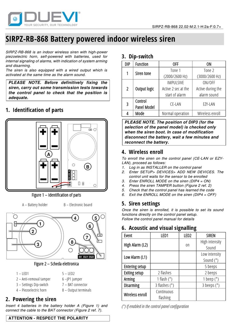
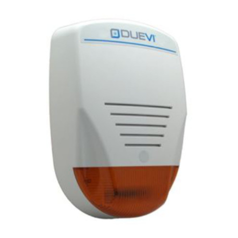
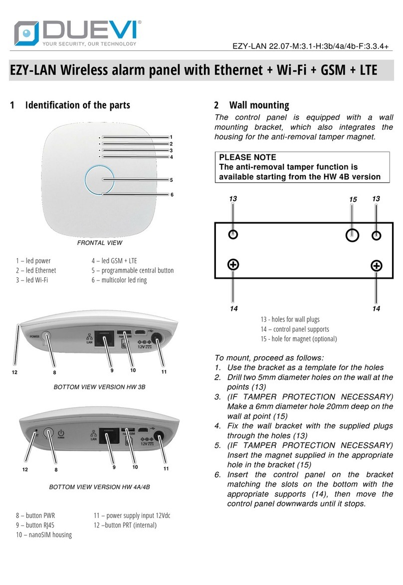
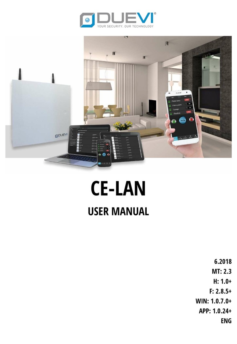
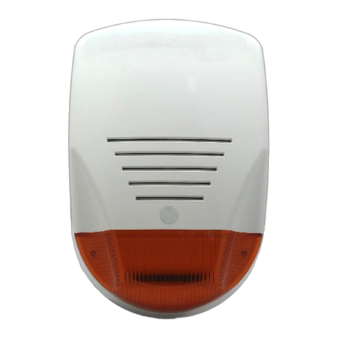
Duevi CE-LAN User manual

CE-LAN
TECHNICAL MANUAL
2.2019
MT: 2.4
H: 1.0+
F: 2.9.3+
WIN: 1.0.7.0+
APP: 1.0.24+
ENG
BEFORE INSTALLING THE SYSTEM READ CAREFULLY ALL THE PARTS OF THIS MANUAL AND KEEP IT CAREFULLY FOR FUTURE
REFERENCE.
THE INSTALLATION OF THE PRODUCT MUST BE CARRIED OUT BY QUALIFIED TECHNICAL PERSONNEL. THE INSTALLER IS
TAKEN TO FOLLOW THE APPLICABLE RULES..

2
SAFETY AND MAINTENANCE RECOMMENDATION
BEFORE POWERING THE CONTROL PANEL, MAKE SURE THAT THE MAINS VOLTAGE IS THE ONE DESCRIBED ON
THIS MANUAL.
IN THE ELECTRICAL SYSTEM TO BE CONNECTED TO THE CONTROL PANEL, A BIPOLAR SECTIONAL DEVICE MUST
BE PROVIDED THAT IT IS EASILY ACCESSIBLE.
DO NOT CONNECT THE UNIT IN VERY WET OR VERY HOT ENVIRONMENT OR CLOSE TO BATHROOM, ETC.
THE COMMUNICATION BETWEEN THE VARIOUS COMPONENTS OF THE SYSTEM COMES IN RADIOFREQUENCY.
BEFORE PERFORMING INSTALLATION, MAKE SURE THAT THE CONTROL PANEL COMMUNICATES CORRECTLY
WITH ALL PERIPHERALS. IT MAY HAPPEN THAT THE CONTROL PANEL DOESN’T RECEIVE CORRECTLY THE SIGNALS
FROM SOME DEVICE. THIS IS DUE TO THE CHARACTERISTICS OF THE ENVIRONMENT IN WHICH THE SYSTEM
WORKS; WALLS IN CONCRETE, METAL BOXES, METALLIC SHELVES, ETC. CAN CREATE PARTICULAR CONDITIONS
OF REFRACTION OF THE SIGNAL OR ATTENUATIONS (FOR EXAMPLE IT IS THE COMMON EXPERIENCE THE LACK
OF SIGNALING OF THE CELL PHONE IN SOME PLACES). TO AVOID THESE INCONVENIENCES AND ALWAYS GET
THE MAXIMUM PERFORMANCE FROM YOUR SYSTEM, IT IS RECOMMENDED TO ALWAYS PERFORM ANY
PRELIMINARY POSITIONING TESTS, IN ORDER TO ENSURE THE ACTUAL QUALITY OF RADIO TESTS.
WARNING: IN THE ELECTRICAL SYSTEM IN WHICH THE CONTROL PANEL IS INSTALLED, AN EXTERNAL
PROTECTION DEVICE SHOULD BE PRESENT AGAINST THE OVERCURRENT AND TROUBLESHOOTING TO THE
GROUND 230V ~ 16A.
ATTENZIONE: NELL’IMPIANTO ELETTRICO IN CUI SI INSTALLA LA CENTRALE DEVE ESSERE PRESENTE UN
DISPOSITIVO ESTERNO DI PROTEZIONE CONTRO LE SOVRACORRENTI E I GUASTI VERSO TERRA (DISPOSITIVO
SALVAVITA) 230V~16A.
THE MANUFACTURER IS NOT LIABLE IN THE EVENT OF IMPROPER USE OF THE PRODUCT, WRONG INSTALLATION
OR FAILURE TO OBSERVE THE INDICATIONS OF THIS MANUAL AND THE FAILURE TO OBSERVE THE LEGISLATION
RELATED TO THE ELECTRICAL SYSTEMS.

3
SUMMARY
1SPECIFICATION.....................................................................................................................................................5
1.1 PCB CONTROL PANEL..............................................................................................................................................5
1.2 TERMINAL BOARD...................................................................................................................................................6
1.3 DIP SWITCH AND LED..............................................................................................................................................7
1.3.1 DIP-SWITCH ON MAIN BOARD........................................................................................................................7
1.3.2 LED ON MAIN BOARD .....................................................................................................................................7
1.4 BUS485....................................................................................................................................................................8
1.5 WIRELESS SECTION .................................................................................................................................................8
1.6 ZONES .....................................................................................................................................................................8
1.7 EXPANSION OF THE WIRED ZONES (OPTIONAL).....................................................................................................9
1.8 EXPANSION OF WIRELESS ZONES 433 (OPTIONAL) ..............................................................................................10
1.9 OUTPUTS (ON MAIN BOARD) ...............................................................................................................................10
1.10 USERS....................................................................................................................................................................10
1.11 AREAS AND SECTORS............................................................................................................................................11
1.12 ACTIVATION, COMMAND AND INTERFACE TOOLS...............................................................................................12
1.13 EVENT MEMORY ...................................................................................................................................................12
1.14 LAN........................................................................................................................................................................12
1.15 GSM / 3G MODULE...............................................................................................................................................12
1.16 FIRMWARE............................................................................................................................................................12
1.17 COMPATIBILITY TABLE ..........................................................................................................................................13
2DESIGN THE SYSTEM ...........................................................................................................................................14
2.1 EXAMPLE OF MAXIMUM CONFIGURATION..........................................................................................................15
2.2 KEYPADS WITH DISPLAY ON BUS485 - MOD. DVT-LCD / DVT-OLED.....................................................................16
2.3 TRANSPONDER KEY READERS ON BUS485 - MOD. LET-485 .................................................................................17
2.4 WIRED ZONES EXPANSION CARDS ON BUS485 - MOD. ESP8-BUS.......................................................................17
2.5 WIRELESS ZONE EXPANSION CARDS 433.92 MHz ON BUS485 - MOD. ESP-R......................................................18
2.6 OUTDOOR SIRENS ON BUS485 - MOD. VV-ZELA-BUS...........................................................................................18
2.7 OUTDOOR WIRED SIREN - MOD. VV-ZELA-F.........................................................................................................19
2.8 WIRED SENSOR (GENERIC, NC TYPE ALARM CONTACT).......................................................................................19
2.9 PEPPER SPRAY DEVICES - MOD. PEPEROSSO AND PEPINO ..................................................................................20
2.10 LAN CONNECTION.................................................................................................................................................21
3MAIN CHARACTERISTICS......................................................................................................................................22
4FIRST SWITCH-ON / RESET OF THE PANEL...............................................................................................................23
5PREPARATION OF PROGRAMMING SOFTWARE........................................................................................................ 24
5.1 "CE-LAN CONNECT" APPLICATION........................................................................................................................24
5.1.1 MANAGEMENT AND UPDATING OF INTERFACES.........................................................................................25
5.1.2 MANAGEMENT OF DEVICES (PANELS)..........................................................................................................25
5.1.3 LIST OF CONTROL PANELS (MAIN PAGE) ......................................................................................................26

4
6ACCESS TO THE PANEL .........................................................................................................................................27
6.1 LOGIN and LOGOUT..............................................................................................................................................27
6.2 NORMAL MODE ....................................................................................................................................................28
6.2.1 DEVICES MENU .............................................................................................................................................28
6.2.2 ZONES MENU................................................................................................................................................30
6.2.3 OUTPUTS MENU ...........................................................................................................................................30
6.2.4 USERS MENU.................................................................................................................................................30
6.2.5 IMAGE LIST MENU ........................................................................................................................................31
6.2.6 EVENTS MENU ..............................................................................................................................................31
6.2.7 LANGUAGE MENU.........................................................................................................................................31
6.3 SETUP MODE.........................................................................................................................................................32
7INSTALLATION - PROGRAMMING STEPS.................................................................................................................33
7.1 PANEL SETTINGS ...................................................................................................................................................34
7.2 DEVICES ON BUS ...................................................................................................................................................37
7.2.1 PROGRAMMING QUICK ARM FOR A KEYPAD...............................................................................................39
7.2.2 PROGRAMMING PARTIALIZATIONS FOR A TAG READER..............................................................................40
7.3 WIRELESS SENSORS AND PERIPHERALS................................................................................................................41
7.3.1 ADD RADIO DEVICES .....................................................................................................................................41
7.3.2 ADD RADIO DEVICE BY SERIAL ......................................................................................................................42
7.3.3 PROGRAMMING OF REMOTE CONTROL BUTTONS......................................................................................42
7.4 ZONES ...................................................................................................................................................................43
7.5 OUTPUTS...............................................................................................................................................................45
7.6 USERS....................................................................................................................................................................46
7.6.1 CREATE / MODIFY A USER.............................................................................................................................46
7.7 IP CAMERAS ..........................................................................................................................................................48
7.7.1 SETTING THE CAMERA ..................................................................................................................................49
7.7.2 ADDING A CAMERA.......................................................................................................................................52
7.8 CONTACT-ID..........................................................................................................................................................53
7.8.1 ADDING A MONITORING STATION ...............................................................................................................53
7.8.2 SETTING THE CONTACT-ID PARAMETERS.....................................................................................................54
7.9 AREAS....................................................................................................................................................................55
7.10 FIRMWARE............................................................................................................................................................63
7.11 LANGUAGE............................................................................................................................................................64
8SAVE / LOAD CONFIGURATION .............................................................................................................................65
8.1 SAVE THE CONFIGURATION..................................................................................................................................65
8.2 LOAD THE CONFIGURATION .................................................................................................................................65

5
1SPECIFICATION
1.1 PCB CONTROL PANEL
Figure 1 –Electric diagram of the control panel

6
1.2 TERMINAL BOARD
VBS1
A1
B1
-VS
BUS485 n. 1
VBS1 = BUS power supply positive (+12 V) / -VS = BUS power supply negative
Max 450 mA (protected by self-resetting polyswitch)
A1 / B1 = BUS data
VBS2
A2
B2
-VS
BUS485 n. 2
VBS2 = BUS power supply positive (+12 V) / -VS = BUS power supply negative
Max 450 mA (protected by self-resetting polyswitch)
A2 / B2 = BUS data
GND
Mass reference exclusively for TMP tamper line and zone inputs IN1 ÷ IN8
TMP
TMP Input by wire tamper line (Normally Closed to GND)
IN1 ÷ IN8
Zone inputs: typically used as alarm zones, they can also be used for other functions (control of devices 24h / 24, panic,
activator...). Electrically you can choose:
NORMALLY CLOSED = zone at rest when closed to GND
NORMALLY OPEN = zone at rest when opened to GND
SINGLE BALANCE = connection with the zone at rest when closed towards GND by resistance 2.2 kΩ, can
detect short-circuit attempts
DOUBLE BALANCE = connection with zone at rest when closed towards GND by resistance 2.2 kΩ and 12 kΩ; it
can detect attempts to short-circuit and tamper/cable cut

7
OUT1 ÷OUT4
+VS
Open Collector programmable outputs (max 20 VDC / 500 mA).
Use the + VS terminal for the positive connection of the outputs according to the following diagram:
Output status: positive + 12V = at rest; GND = active (this behaviour can be reversed in: SETUP> OUTPUTS> Output
Settings). The outputs can be set to IMPULSIVE or MONOSTABLE.
The OpenCollector outputs are electronic, so they cannot be connected directly to a load or to an input as for the relay
outputs and OptoMOS (solid state relay).
+VS +VS
-VS -VS
+VS = Positive +12 V output for powering sensors and devices
-VS = Negative reference for powering sensors and devices (DO NOT USE as a reference of the inputs zone IN1 ÷ IN8
and / or TMP tamper line)
NCI
NOT USED
+SA
+SA = Positive +12 V output for powering a siren (max 450 mA)
+S
+C
Output relay designed for the sound command of the wired sirens. This output is identified as “OUT.SIR”/ “RELE 5”.
The output is available in the two opposite modes of operation:
+S = Positive control +12 V given in alarm (REST=0 V / ACTIVE = +12 V)
+C = Positive control +12 V missing in alarm (REST=+12 V / ACTIVE = 0 V)
Note: this output must be associated with the "ALARM" and / or "PRE-ALARM" event (it is however possible to associate
it freely also to other events)
C
NO
NC
Dry contact relay output, programmable (max 24 VDC / 500 mA or 120 VAC / 500 mA)
This output is identified as “OUT.REL” / “RELE 6”.
C= Common terminal; NO = Normally Open Terminal; NC = Normally Closed Terminal
1.3 DIP SWITCH AND LED
1.3.1 DIP-SWITCH ON MAIN BOARD
Num
Function
OFF
ON
1
RESERVED
OBLIGATORY POSITION
DO NOT USE
2
RESERVED
DO NOT USE
OBLIGATORY POSITION
3
FACTORY RESET
Normal operation
Reset factory settings at start-up
4
WEB ACCESS PROTECTION
Web access without password
INSTALLER ACCESS ALWAYS ENABLED
Web access with password
5
RESERVED
OBLIGATORY POSITION
DO NOT USE
6
RESERVED
DO NOT USE
OBLIGATORY POSITION
1.3.2 LED ON MAIN BOARD
Num
Function
OFF
ON
1
3G CONNECTION
Absent
Solid ON = 3G
Flashing = GSM
2
NOTIFICATIONS SEND
stand-by
sending in progress
3
RADIO COMMUNICATION
stand-by
communication in progress
4
INTERNET ON LAN
Absent
Present
5
P2P CONNECTION
Absent
Present

8
1.4 BUS485
! Always check the maximum consumption reached on the BUS under maximum load conditions!
Features
Double RS485 BUS
Maximum consumption (for BUS)
Max 450 mA
BUS protection
Poliswitch 750 mA max, self-resetting
Compatibility
Activators:
transponder key reader mod. LET-485
keypad with display mod. DVT-LCD or DVT-OLED
Sirens:
siren mod. VV-ZELA-BUS
Accessories:
wired zone expansion card and outputs mod. ESP8-BUS
433.92 MHz radio zone expansion card mod. ESP-R
1.5 WIRELESS SECTION
Features
n. 2 bi-directional radio sections (RTX):
n. 1 section dedicated to alarm
n. 1 section dedicated to wireless video-verification
Working frequency
869,65-867,00 MHz
Type of communication
Bidirectional, multi-channel FM with Listen Before Talk and Frequency Hopping
Range (open field)
Alarm section: approx. 200 m
Video-verification section: approx. 100 m
Wireless encoding
AES 128 bit
Wireless zones
Programming by auto-learning or serial code
1.6 ZONES
Total number of zones (wired and / or radio): 128
It is possible to add / create any number of radio or wired zones within the total limit:
the wired zones are added by connecting the appropriate expansion cards (model ESP8-BUS) or other peripherals (ex: each
keypad mod. DVT-LCD / OLED adds a wired zone)
Wireless zones are added by programming (memorizing) radio sensors or other radio devices (ex: each MINI-C sensor adds 4
zones, one for each detection technology inside it)
WIRED ZONE ON BOARD
Factory reference
Name: "IN 1_1" ÷ "IN 8_1"
Description: "IN x on Main Board"
Number
n. 8 wire zones (reference to GND)
Type
Normally Closed
Normally Open
Single Balance (with 2.2 kΩ resistance)
Double balance (with 2.2 kΩ and 12 kΩ resistance)
Mode
PRE-ALARM (L1) - Low level alarm.

9
A violation of a PRE-ALARM zone generates a low-level alarm.
If - within a pre-established time - a second violation of a PRE-ALARM zone occurs (ex: violation of the same
zone or another PRE-ALARM zone) then a high level ALARM begins (see description ALARM).
If the second violation of a PRE-ALARM zone occurs after the pre-set time, there is again a PRE-ALARM low-
level alarm.
It is possible to completely customize which actions the control panel will perform in case of PRE-ALARM
(ex.: no sound of sirens, sending only SMS ...).
ALARM (L2) - High level alarm.
The violation of an ALARM zone always generates a high level alarm.
It is possible to completely customize which actions the control panel will perform in case of ALARM (ex.:
high-power sirens sound, sending calls and SMS ...).
AND
The alarm is generated if the two zones selected detect both intrusion within an AND time. It is possible to
set the alarm level (PRE-ALARM or ALARM).
INSTANTANEOUS
Instantaneous zones immediately generate an alarm (of the PRE-ALARM or ALARM type) when they detect.
DELAYED
The delayed zones - when violated - start the Entry time before generating an alarm (PRE-ALARM or ALARM
type).
If the control panel is disarmed within the Entry time, there will be no alarm.
SILENT
When the Silent zone is violated, there will be no warning (no sirens sound or visible signals) but Silent
Alarm communications will start (SMS and calls to programmed numbers).
TECHNOLOGICAL
The Technology zones are active 24h / 24 even when the system is disarmed.
These zones are intended for use with detectors such as: flooding, smoke, gas ...
PANIC
When a panic zone is violated, the sirens sound to get immediate attention. Panic Alarm messages are sent
(SMS and calls to programmed numbers).
ACTIVATOR (IMPULSIVE / MONOSTABLE)
The Activator zones are used to arm / disarm the system by means of a button or key. It is activated each
Sector in which the zone has been added.
INSTANTANEOUS + ALERT
Like the Instant zones; when the panel is disarmed - their detection starts an acoustic warning.
DELAYED + ALERT
Like the Delayed zones; when the panel is disarmed - their detection starts an acoustic warning.
1.7 EXPANSION OF THE WIRED ZONES (OPTIONAL)
Device
ESP8-BUS (BUS485 expansion card for wired zones)
Factory reference
Name: "IN 1_n" ÷ "IN 8_n" (n = depends on the order in which the device was added)
Description: “IN x on ESP8-BUS”
Number
n. 8 wired zones (reference to GND)
Type
Normally Closed
Normally Open
Single Balance (with 2.2 kΩ resistance)

10
Double balance (with 2.2 kΩ and 12 kΩ resistance)
Mode
(see description "Wired zones on board")
1.8 EXPANSION OF WIRELESS ZONES 433 (OPTIONAL)
Device
ESP-R (BUS485 expansion card for wireless zones)
Working frequency
433,92 MHz
Range
100 m (in open field)
Factory reference
Name: "IN 1_n" ÷ "IN 8_n" (n = depends on the order in which the device was added)
Description: “IN x on ESP-R”
Number
n. 8 wireless zones
Mode
(see description "Wired zones on board")
1.9 OUTPUTS (ON MAIN BOARD)
Features
All the outputs on the control panel are programmable.
The outputs can be associated to any Area (even to several Areas at the same time)
Each output can be programmed for multiple EVENTS at the same time
TYPE
ON / OFF ON EVENT: the output follows the event state to which it is associated, it
remains active as long as the event remains
ON / OFF ON COMMAND: the output is controlled manually by the App
IMPULSIVE (pulse duration adjustable from 1 to 255 seconds): the output activates
when the event takes place and for the set time, then goes back to rest. It can also be
manually controlled by the App.
State at rest (MODE)
Normally Open
Normally Closed
Events
PANEL STATUS: DISARMED
PANEL STATUS: ARMED
ARMING
PRE-ALARM
ENTRY TIME
MANUMISSION
ALARM
MAINTENANCE
TECHNOLOGICAL
PANIC
SILENT
TAMPER
MANUAL CONTROL
Open Collector outputs
No. 4 Open Collector outputs
"Siren" output
N. 1 Alarm relay per siren (positive command to give/missing)
Terminals: (+S / +C)
"Dry contact” relay output
N. 1 dry contact Alarm relay (C, N.O., N.C.)
1.10 USERS
Maximum number of Users per Panel
128
User Features
User Name
Customizable (max 14 characters)
User Type (global)
Normal: this type of User can arm / disarm the Area (or
Areas) to which it is associated. It cannot display the
general information of the system.

11
Administrator: as the normal user, but he can view the
general information of the system and enable the Installer
access
User Type (Area)
Master: User without limitations
Service: Service user, he can only disarm
Permits on the sectors
of an area
It is possible to limit the permission of the User to arm /
disarm on one or more Sectors of the Area
Timetable (Area)
It is possible to define a weekly timetable in which the User is
enabled or not on the Area
SMS / MAIL / PUSH
alerts
Global information from the system:
Power supply information
Service information
Panel malfunctions
LAN / 3G Status ("LAN / 3G Information")
Information from the Area:
Alarm / Pre-alarm events
Panic Events / Silent Alarm / 24H Zones
Change of the Area status
Maximum number of Activators per User
6 (total)
Keypad User Code (max 1)
Web / email access (max 1)
Remote control
Transponder Keys
Maximum number of emails per User
2 (only the main one is used for web / app access)
Telephone numbers
Landline Telephone
Max n. 1 landline phone number
Mobile phone
Max n. 1 mobile phone number
1.11 AREAS AND SECTORS
Characteristics of the Areas
Max number Areas
8
Names of the Areas
Each Area can be named as desired (max 14 characters).
The name is displayed in the warning messages (SMS, e-mail), in
the events, in the keypad display, read in voice calls (only if TTS is
available)
Functions of the Areas
The list of the settings of each Area follows:
Entry Time
Exit Time
Pre-Alarm Time
Alarm Time
AND time
Open Doors Function
Sounds and Alerts
Auto-Arm / Disarm
Number of Sectors by Area
4
Max number of Users per Area
50 Standard Users (without weekly time limitation)
PLEASE NOTE: Users limited to weekly time occupy the equivalent
space of about 3 standard Users
Max number of Zones per Area
128 (see Sector limits)
Max number of Outputs per Area
16

12
Max number of Activators per Area
8
Characteristics of Sectors
Max number of zones per Sector
32
Sector names
Each Sector can be named as you like (max 13 characters)
Zones in the Sectors
All zones of the control panel can be added to a Sector.
The same zone can be added to several Sectors at the same time.
Within Sectors it is possible to create the zone AND.
Sectors in Common between Areas
Sector 4 of an Area may be associated with other Sectors 4 of others
Areas to create a Common Group of Sectors 4 (max 3 groups). There
will be an alarm from the Sectors 4 of a Common Group only if ALL
the Areas involved in the Group are armed with Sector 4 active.
1.12 ACTIVATION, COMMAND AND INTERFACE TOOLS
Activators on BUS
Maximum total number of activators on
BUS485
8
[always check the maximum consumption reached
on BUS in maximum load conditions]
Keypads with display
Mod. DVT-LCD / DVT-OLED
Transponder key readers
Mod. LET-485
App / Web / Software
Local and remote access interface (LAN / Internet connection)
Hardware keys
Zone inputs set as "Arming"
Remote controls
Mod. TX6C
1.13 EVENT MEMORY
GLOBAL event memory
Up to 5000 events recorded in permanent memory (consulted by Installer and Administrators)
AREAS events memory
Memory of events since the last arming (available to all belonging Users of the Area)
1.14 LAN
Connection type
10/100 Mbps Ethernet LAN \ Integrated switch, n. 2 RJ45 LAN connectors
Integrated Peer to Peer (P2P)
The control panel is equipped with an automatic network configuration system for remote
access (it does not require modem / router configuration)
1.15 GSM / 3G MODULE
Module features *
Functions that can be used thanks to the module:
Sending voice calls EVENTS (with / without TTS **): alarm, panic, rescue...
Sending SMS events
Data connection *
Data connection via GSM / 3G
TTS **
Voice reading of Alarms / Areas / Sectors / Zones / Address for voice calls
*The characteristics may vary depending on the model of GSM / 3G module installed and the services active on the SIM
** The TTS feauture is only available for ITALIAN LANGUAGE and depends from the GSM / 3G module model installed
1.16 FIRMWARE
The control panel firmware can be updated (see the "FW update" settings from Installer access> SETUP)

13
1.17 COMPATIBILITY TABLE
Code
Product
Firmware (minimum version)
DVT-LCD / DVT-OLED
Keypad with display on BUS
1.61
LET-485
Transponder key reader on BUS
1.44
ESP8-BUS
Zone expansion card on BUS
2.1
VV-ZELA-BUS
Siren on BUS
1.1
ESP-R
433 Wireless zone expansion card on BUS
1.1

14
2DESIGN THE SYSTEM
THE CE-LAN PANEL HAS BEEN DESIGNED FOR SMALL / MEDIUM DIMENSION PLANTS.
THE TECHNICAL CHARACTERISTICS OF THE PANEL - WHICH ARE TYPICAL OF THE BIG INSTALLATIONS (EX: 128 ZONE
MAX) - CANNOT BE USED TO THE MAXIMUM LIMIT IN ALL CONDITIONS.
PAY PARTICULAR ATTENTION TO THE CONSUMPTION TO WHICH YOU SUBMIT EVERY SECTION OF THE PANEL (BUS,
POWER OUTPUTS, SIREN OUTPUTS, ETC.).
DRAWING THE ALARM SYSTEM AND BE AWARE THAT THE MAXIMUM CONFIGURATION MUST ALWAYS RESPECT THE
MAXIMUM CONSUMPTION LOAD.
Following are some basic considerations:
The maximum number of connectable peripherals depends on the total consumption
Code
Consumption
DVT-LCD
30 mA (at stand-by) / 160 mA (active)
DVT-OLED
50 mA (at stand-by) / 120 mA (attiva)
LET-485
23 mA (at stand-by) / 30 mA (attivo)
ESP8-BUS
50 mA (without powering sensors from the card)
VV-ZELA-BUS
9 mA (at stand-by) / 13 mA (con LED) *
ESP-R
60 mA
*ATTENTION: the sirens must be connected only if they have a battery (charged and in good condition) because the consumption in alarm –that exceeds
the maximum values of the BUS - it is supplied by the battery itself without overloading the BUS
The quality of the connections plays an important role especially for the BUS.
In the following table we can see an estimate of the voltage drop caused by two typical cables normally used for alarm connections
in different working conditions; appropriately select the most suitable one for the installation (section, distance, measured
voltage...):
Cable type (sections: power
+ signals)
Current consumption
Distance
Voltage drop at the end of
BUS connection
2 x 0,50 + 4 x 0,22 [mm2]
450 mA
20 m
0,6 V
40 m
1,2 V
80 m
2,5 V
200 mA
20 m
0,3 V
40 m
0,5 V
80 m
1,1 V
2 x 0,75 + 4 x 0,22 [mm2]
450 mA
20 m
0,4 V
40 m
0,8 V
80 m
1,6 V
200 mA
20 m
0,2 V
40 m
0,4 V
80 m
0,8 V
As you can see, the voltage drop strongly depends on the section of the power cable (it improves increasing the section), from
current absorption (it worsen by increasing the consumption) and from the distance (it worsen by increasing the distance)

15
Consider the installation position of both the control panel and the wireless peripherals, in order to optimize the radio range of
the system; the panel should be in the hypothetical centre of the radio space to be covered: in this way the distance towards the
radio peripherals is always the minimum, ensuring better communication quality and lower consumption.
The maximum number of zones available (128) can only be reached if absorption limits are not exceeded; pay attention to the
number of zones that each device (BUS and radio) adds / occupies
When creating Areas, the various resources (zones, users, outputs...) must be appropriately distributed in a balanced way
The higher the number of notifications (SMS, VOICE, E-MAIL) the longer it will take to complete the communications
2.1 EXAMPLE OF MAXIMUM CONFIGURATION
In the following configuration example we assume to create a system with these features:
n. 4 Areas
n. 1 Keyboard for each Area
n. 1 Transponder key reader for each area
n. 128 total zones (76 wired zones / 36 radio zones 868 MHz / 16 radio zones 433 MHz)
n. 1 Wired siren
Power supply of peripherals on the appropriate outputs [+ VS | + VS | -VS | -VS]
The sizing of the system - verifying the absorptions, the number of zones and the distribution of loads - is:
Device
Quantity
Consumption *
Zones
PANEL
1
-
8 wired
ESP8-BUS
8
8 x 50 mA = 400 mA
8 x 8 wired = 64 zones
ESP-R
2
2 x 60 mA = 120 mA
2 x 8 wireless 433 MHz = 16 zones
DVT-OLED
4
4 x 120 mA = 480 mA
4 x 1 wired = 4 zones
LET-485
4
4 x 30 mA = 120 mA
-
MINI-C
7
-
7 x 4 wireless = 28 zones
MINI-M
4
-
4 x 1 wireless = 4 zones
DIRRV2
4
-
4 x 1 wireless = 4 zones
VV-ZELA-F
1
25 mA (stand-by) / 1,9 A (in alarm)
-
TOTAL
1,14 A
128 zones
*Note: for the calculation, the maximum consumption of each peripheral (usually of limited duration) were taken, except for the siren (whose peak of absorption must
necessarily supplied by the battery on board)
A connection diagram can be summarized in the following table (as you can see, you need to deploy the devices on the two BUSs to balance
the absorption):
BUS 1
[ VBS1 | A1 | B1 | –VS ]
BUS 2
[ VBS2 | A2 | B2 | –VS ]
OUT SIREN
[ +SA | +S | +C ]
OUT POWER
[ +VS | +VS | –VS | –VS ]
n. 2 DVT-OLED
n. 2 DVT-OLED
n. 1 VV-ZELA-F
n. 2 LET-485
n. 2 LET-485
n. 4 ESP8-BUS
n. 4 ESP8-BUS
n. 1 ESP-R
n. 1 ESP-R
Absorption
410 mA (peak 560 mA *)
25 mA (peak 1,9 A **)
Max 450 mA
*In conditions of maximum consumption
** The consumption peak in alarm must be supported by the siren battery

16
2.2 KEYPADS WITH DISPLAY ON BUS485 - MOD. DVT-LCD / DVT-OLED
! Pay attention to the maximum consumption (450 mA per BUS), MAX 8 ACTIVATION DEVICES ON EACH BUS!
Figure 2 –Example of keyboard connection with display mod. DVT-LCD / OLED to BUS1
The keypads can be connected indifferently on the BUS1 or BUS2. The addressing is independent on the two BUS.
To program the address of the keypads:
On the keypad, set DIP2 = ON
Power supply the keypad (the keypad is powered by the BUS)
Press the F1 and 1buttons simultaneously: the KEYPAD PROGRAMMING menu appears
Select the ADDRESS item and confirm with
Set an address from 01 to 08 (be careful not to give the same address of other keypads on the same BUS!) Then press
Exit the menu, the keypad is programmed
DVT-OLED CONSUMPTION: ABOUT 50 mA (STAND-BY) / 120 mA (ACTIVE)
DVT-LCD CONSUMPTION: ABOUT 30 mA (STAND-BY) / 160 mA (ACTIVE)

17
2.3 TRANSPONDER KEY READERS ON BUS485 - MOD. LET-485
! Pay attention to the maximum consumption (450 mA per BUS), MAX 8 ACTIVATION DEVICES ON EACH BUS!
Figure 3 –Example of connection of the transponder key reader mod. LET-485 to BUS1
2.4 WIRED ZONES EXPANSION CARDS ON BUS485 - MOD. ESP8-BUS
! Pay attention to maximum consumption (450 mA per BUS)!
Figure 4 –Example of connection of the zones expansion card mod. ESP8-BUS
ESP8-BUS CONSUMPTION: ABOUT 50 mA
LET-485 CONSUMPTION: ABOUT 30 mA
! WARNING!
TO USE CORRECTLY THE ESP8-BUS CARD WITH
THE PANEL, PUT DIP6 AND DIP7 ON ON

18
2.5 WIRELESS ZONE EXPANSION CARDS 433.92 MHz ON BUS485 - MOD. ESP-R
! Pay attention to maximum consumption (450 mA per BUS)!
Figure 5 –Example of connection of the 433.92 MHz radio expansion card mod. ESP-R
2.6 OUTDOOR SIRENS ON BUS485 - MOD. VV-ZELA-BUS
! Pay attention to maximum consumption (450 mA per BUS)!
Figure 6 –Example of connection of the siren on BUS mod. VV-ZELA-BUS
ESP-R consumption: approx. 60 mA
Consumption VV-ZELA-BUS: about 13
mA (stand-by!)
!WARNING!
THE SIREN MUST MANDATORY TO
BE EQUIPPED WITH A WORKING
AND CHARGED BATTERY.

19
2.7 OUTDOOR WIRED SIREN - MOD. VV-ZELA-F
! THE SIREN MUST MANDATORY TO BE EQUIPPED WITH A WORKING AND CHARGED BATTERY, TO AVOID AN
EXCESSIVE CONSUMPTION IN ALARM (WHICH COULD DAMAGE THE CONTROL PANEL)!
! PAY ATTENTION TO THE MAXIMUM CONSUMPTION (450 mA PER + SA)!
Figure 7 –Example of connection of the wired siren mod. VV-ZELA-F
2.8 WIRED SENSOR (GENERIC, NC TYPE ALARM CONTACT)
Figure 8 –Example of connection of a generic sensor
!WARNING!
Set the siren as follows:
DIP1 = ON
DIP3 = ON
!WARNING!
Set the OUT.SIR output (terminals + S
/ + C) as ON / OFF ON EVENT and
associate it with the ALARM and PRE-
ALARM events
!WARNING!
Set the OUT.REL output (terminals C /
NO / NC) as ON / OFF ON EVENT and
associate it with the ARMED event in
the Area.

20
2.9 PEPPER SPRAY DEVICES - MOD. PEPEROSSO AND PEPINO
Figure 9 –Example of connection of the pepper spray mod. PEPEROSSO and mod. PEPINO
! WARNING !
Set the OUT.SIR output (terminals + S
/ + C) as ON / OFF ON EVENT and
associate it with the ALARM and / or
PRE-ALARM events
! WARNING !
Set the OUT.REL output (terminals C /
NO / NC) as ON / OFF ON EVENT and
associate it with the ARMED event in
the Area.
! WARNING !
Set the OUT.SIR output (terminals + S
/ + C) as ON / OFF ON EVENT and
associate it with the ALARM and / or
PRE-ALARM events
! WARNING !
Set the OUT.REL output (terminals C /
NO / NC) as ON / OFF ON EVENT and
associate it with the ARMED event in
the Area.
Other manuals for CE-LAN
1
Table of contents
Other Duevi Security System manuals