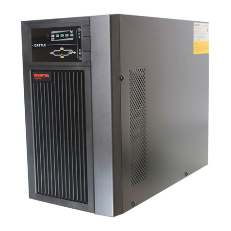
Santak CASTLE Series User manual

CASTLE Series
3C3 HD 20-80 kW USER MANUAL


Thank you for choosing Santak products!
Please adhere to the warnings and instructions specied in the manual and on the equipment, and keep the
manual properly for future reference. Do not try to operate the equipment before reading all the safety information
and operation instructions
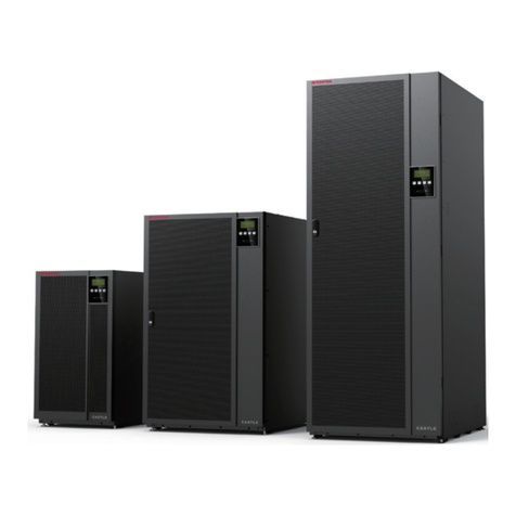
The manual applies to the 3C3 HD series, including:
3C3 HD-20K
3C3 HD-30K
3C3 HD-40K
3C3 HD-60K
3C3 HD-80K

IMPORTANT SAFETY INSTRUCTIONS
SAVE THESE INSTRUCTIONS
This manual contains important instructions that you should follow during installation and maintenance of
the UPS and batteries. Please read all instructions before operating the equipment and save this manual
for future reference.
2022 Santak Corporation
The contents of this manual are the copyright of the publisher and may not be reproduced (even extracts) without
the written approval of Santak Corporation. Every care has been taken to ensure the accuracy of the information
contained in this manual, but no liability can be accepted for any errors or omission. The right to make design
modications is reserved.
©
All Rights Reserved
WARNING
This is a product for commercial and industrial applicaon for Level 2 environment. Installaon
restricons or addional measures may be needed to prevent disturbances.

Santak 3C3 HD 20-80 kW UPS
Installation and Operation Manual
i
Copyright © 2022 Santak Corporation plc. All rights reserved.
Table of Contents
Chapter 1 SAFETY INSTRUCTIONSTIONS........................................................................................................................................................................................................................................................................ viivii
1.1. Certication........................................................................................................................................................2
1.2. User Precautions ............................................................................................................................................... 2
1.3. Conventions Used in this Manual ...................................................................................................................... 3
1.4. Environment ...................................................................................................................................................... 5
1.5. Getting Help.......................................................................................................................................................5
Chapter 2 INTRODUCTION .................................................................................................................................................... 6
2.1. Internal structure of UPS system ....................................................................................................................... 9
2.2. Operation modes of the UPS...........................................................................................................................10
2.2.1. AC power online operation mode ........................................................................................................ 10
2.2.2. Battery Mode ....................................................................................................................................... 13
2.2.3. Bypass Mode ....................................................................................................................................... 14
2.3. Features of the UPS ....................................................................................................................................... 15
2.3.1. Advanced Battery Management(ABM) ................................................................................................ 15
2.3.2. HotSync wireless parallel technology (HotSync) ................................................................................. 15
2.3.3. Software and communication features ................................................................................................ 15
2.3.4. User interface ...................................................................................................................................... 15
2.3.5. Power supply management software .................................................................................................. 16
2.4. Battery system ................................................................................................................................................. 16
2.5. Basic system conguration .............................................................................................................................. 16
Chapter 3 UPS INSTALLATION PLAN ................................................................................................................................ 17
3.1. Creating an Installation Plan............................................................................................................................17
3.2. Site Preparations ............................................................................................................................................. 18
3.2.1. Environmental and Installation precautions ......................................................................................... 18
3.2.2. Power supply and wiring preparation of the UPS system .................................................................... 23
3.2.3. Preparation for UPS interface wiring ................................................................................................... 28
Chapter 4 UPS SYSTEM INSTALLATION............................................................................................................................ 29
4.1. Preliminary Installation Information ................................................................................................................. 29
4.2. UPS Cabinet Inspection and Unpacking ......................................................................................................... 29
4.3. System Installation ......................................................................................................................................... 33
4.3.1. Mechanical installation ........................................................................................................................ 33
4.3.2. Cable installation ................................................................................................................................. 33
4.4. Installation of external battery cabinet ............................................................................................................. 36
4.4.1. Supported battery congurations ......................................................................................................... 37
4.5. Wiring of the UPS Parallel System .................................................................................................................. 39
4.5.1. Overview of power cables ................................................................................................................... 39
4.5.2. Control signal overview ....................................................................................................................... 41
4.5.3. Installation of the parallel control wiring ............................................................................................... 41

ii Copyright © 2022 Santak Corporation plc. All rights reserved.
Chapter 5 COMMUNICATION INTERFACES ....................................................................................................................... 43
5.1. Mini-slots ......................................................................................................................................................... 45
5.2. Intelligent Power Manager (IPM) Software ...................................................................................................... 47
5.3. Signal input Monitoring .................................................................................................................................... 47
Chapter 6 UPS OPERATING INSTRUCTIONS .................................................................................................................... 48
6.1. UPS Control Panel and Indicator Lamps ......................................................................................................... 48
6.1.1. Control Panel ....................................................................................................................................... 48
6.2. Use of LCD Control Panel ...............................................................................................................................50
6.2.1. Status indicator lamps ......................................................................................................................... 50
6.2.2. System logs ......................................................................................................................................... 50
6.2.3. Use of touch screen ............................................................................................................................. 51
6.2.4. Use menu ............................................................................................................................................ 51
6.2.5. Meters .................................................................................................................................................. 52
6.2.6. System Control Instructions ................................................................................................................. 54
6.2.7. Use of Log menu ................................................................................................................................ 57
6.2.8. Use of Info. menu ................................................................................................................................ 59
6.2.9. Use of Setting menu ............................................................................................................................ 59
6.2.10. Use of service reminder function ....................................................................................................... 65
6.3. System operation.............................................................................................................................................68
6.3.1. Start the UPS in "Online" mode (default mode) .................................................................................. 68
6.3.2. Start the UPS in “Bypass” mode ......................................................................................................... 68
6.3.3. Switch from “Online” mode to “Bypass” mode .................................................................................... 69
6.3.4. Switch from “Bypass” mode to “Online” mode .................................................................................... 69
6.3.5. Switch from “Online” mode to “ECO” mode ........................................................................................ 70
6.3.6. Switch from “ECO” mode to “Online” mode ........................................................................................ 70
6.3.7. System shutdown ................................................................................................................. 70
6.4. Single-UPS Operation .....................................................................................................................................71
6.4.1. Single-UPS startup .............................................................................................................................71
6.4.2. UPS shutdown .................................................................................................................................... 72
6.5. Use of Remote Emergency Power O (REPO) Switch ................................................................................... 73
6.6. Transfer the UPS from Double Conversion Mode to Maintenance Bypass Mode ........................................... 74
6.7. Switch from “Maintenance Bypass” Mode to “Online” Mode ...........................................................................75
Chapter 7 UPS MAINTENANCE........................................................................................................................................... 76
7.1. Important Safety Instructions .......................................................................................................................... 76
7.2. Carry out Preventive Maintenance .................................................................................................................77
7.2.1. Daily Maintenance ............................................................................................................................... 77
7.2.2. Monthly maintenance .......................................................................................................................... 77
7.2.3. Regular maintenance .......................................................................................................................... 79
7.2.4. Annual maintenance ............................................................................................................................ 79
7.2.5. Battery maintenance ............................................................................................................................ 79
7.3. Installation of Battery ....................................................................................................................................... 79
7.4. Maintenance Training ...................................................................................................................................... 80
Chapter 8 Technical Indicators of Product ........................................................................................................................ 81

Santak 3C3 HD 20-80 kW UPS
Installation and Operation Manual
iii
Copyright © 2022 Santak Corporation plc. All rights reserved.
8.1. Models .............................................................................................................................................................81
8.2. Technical Indicators ......................................................................................................................................... 81
8.2.1. Standard .............................................................................................................................................. 81
8.2.2. UPS input ............................................................................................................................................ 82
8.2.3. UPS output .......................................................................................................................................... 82
8.2.4. Battery specications ........................................................................................................................... 83
8.2.5. Environment ........................................................................................................................................ 83
Chapter 9 WARRANTY ......................................................................................................................................................... 85
Chapter 10 INSTALLATION CHECKLIST ............................................................................................................................ 86

iv Copyright © 2022 Santak Corporation plc. All rights reserved.
List of Figures
Figure 2-1: 3C3 HD UPS ........................................................................................................................................................ 6
Figure 2-2: Structure of 20-40k product ................................................................................................................................. 7
Figure 2-3: Structure of 60-80k product.................................................................................................................................. 8
Figure 2-4: 3C3 HD UPS Wiring Diagram .............................................................................................................................. 9
Figure 2-5: Route of the electric energy running through the UPS in Online mode ..............................................................11
Figure 2-6: Route of the electric energy running through the UPS in ECO mode ................................................................ 12
Figure 2-7: Route of the electric energy running through the UPS in battery mode ............................................................. 13
Figure 2-8: Route of the electric energy running through the UPS in bypass mode ............................................................ 14
Figure 3-1: Clearance for the UPS cabinet........................................................................................................................... 20
Figure 3-2: UPS dimensions (20–40k) ................................................................................................................................ 21
Figure 3-3: UPS dimensions (60–80k) ................................................................................................................................. 22
Figure 4-1: 20–40k unpacking diagram ................................................................................................................................ 31
Figure 4-2: 60–80k unpacking diagram ................................................................................................................................ 32
Figure 4-3: Gland Plate and Connector Locations .............................................................................................................. 34
Figure 4-4: Locations of cover plate and connecting terminals (60–80k) ............................................................................. 35
Figure 4-5: Schematic diagram of the parallel UPS system ................................................................................................. 39
Figure 4-6: Simplied wiring of CAN and Pull-Chain of the parallel UPS system................................................................. 40
Figure 5-1: Communication Interfaces ................................................................................................................................. 41
Figure 5-2: Gigabit Network Card ......................................................................................................................................... 43
Figure 5-3: Second-generation Environmental Monitoring Probe ........................................................................................ 43
Figure 5-4: Industrial Gateway Card..................................................................................................................................... 44
Figure 5-5: Standard AS400/RS232 card ............................................................................................................................. 44
Figure 6-1: UPS Controls and Indicators .............................................................................................................................. 47
Figure 6-2: Components of the touch screen (Home interface) ........................................................................................... 49
Figure 6-3: Menu interface ................................................................................................................................................... 50
Figure 6-4: Input interface .................................................................................................................................................... 51
Figure 6-5: Output interface.................................................................................................................................................. 51
Figure 6-6: Bypass interface................................................................................................................................................. 51
Figure 6-7: Battery interface ................................................................................................................................................. 52
Figure 6-8: Password verication interface .......................................................................................................................... 52
Figure 6-9: System interface ............................................................................................................................................... 53
Figure 6-10: Switch to bypass interface ............................................................................................................................... 53
Figure 6-11: Conrmation interface ...................................................................................................................................... 54
Figure 6-12: UPS interface .................................................................................................................................................. 54
Figure 6-13: UPM interface .................................................................................................................................................. 55
Figure 6-14: UPM shutdown interface .................................................................................................................................. 55
Figure 6-15: Active Log interface .......................................................................................................................................... 56
Figure 6-16: History Log interface ........................................................................................................................................ 56
Figure 6-17: Clear Log interface ........................................................................................................................................... 56
Figure 6-18: Info. interface 1 ................................................................................................................................................ 57
Figure 6-19: Info. interface 2 ................................................................................................................................................ 57
Figure 6-20: Password verication setting interface ............................................................................................................. 58

Figure 6-21: Setting interface .............................................................................................................................................. 58

Santak 3C3 HD 20-80 kW UPS
Installation and Operation Manual
v
Copyright © 2022 Santak Corporation plc. All rights reserved.
Figure 6-22: Setting - General interface ............................................................................................................................... 59
Figure 6-23: Setting - General - Time interface ................................................................................................................... 59
Figure 6-24: Setting - Output interface ................................................................................................................................. 60
Figure 6-25: Setting - Meters interface ................................................................................................................................. 60
Figure 6-26: Setting - Password interface ........................................................................................................................... 60
Figure 6-27: Control password modication interface .......................................................................................................... 61
Figure 6-28: Control password modication interface ......................................................................................................... 61
Figure 6-29: Control password modication interface ......................................................................................................... 62
Figure 6-30: Control password modication interface .......................................................................................................... 62
Figure 6-31: Setting password modication interface.......................................................................................................... 63
Figure 6-32: Service maintenance reminder interface.......................................................................................................... 63
Figure 6-33: Service maintenance reminder setting interface ............................................................................................. 64
Figure 6-34: Location of service reminder function ............................................................................................................. 64
Figure 6-35: Service reminder settings page........................................................................................................................ 65
Figure 6-36: Fan replacement reminder settings................................................................................................................. 65
Figure 6-37: Switch status in online mode............................................................................................................................ 72
Figure 6-38: Switch status in maintenance bypass mode .................................................................................................... 72
Figure 6-39: Switch status in Maintenance Bypass Mode .................................................................................................... 73
Figure 6-40: Switch status in online mode............................................................................................................................ 73
Figure 7-1: Location of 20–40k air lter screen .................................................................................................................... 76
Figure 7-2: Location of 60–80k air lter screen .................................................................................................................... 76

vi Copyright © 2022 Santak Corporation plc. All rights reserved.
List of Tables
Table 1-1: Acronyms and Abbreviations ................................................................................................................................. 4
Table 2-1: Standards and optional UPS accessories: .......................................................................................................... 16
Table 3-1: Dimensions and Weights ..................................................................................................................................... 19
Table 3-2: Space reservation for the UPS cabinet................................................................................................................ 20
Table 3-3: Requirements on rated input/output and external wiring of the UPS (unit:mm2) ................................................. 24
Table 3-4: Requirements on 20K connecting terminals and torque ...................................................................................... 25
Table 3-5: Requirements on 30–40K connecting terminals and torques .............................................................................. 26
Table 3-6: Requirements on 60–80K connecting terminals and torques .............................................................................. 27
Table 6-1: Status indicator lamps ......................................................................................................................................... 50
Table 6-2: Options displayed on the menu ........................................................................................................................... 52
Table 6-3: Menu of Meters functions .................................................................................................................................... 52
Table 6-4: Structure of Control menu.................................................................................................................................... 54
Table 6-5: Structure of Log menu ......................................................................................................................................... 57
Table 6-6: Structure of Setting menu .................................................................................................................................... 60
Table 8-1: Gas concentrations recommended in Table B1 of ANSI/ISA-71.04-2013 for G1 equipment environment .......... 84
Table 8-2: Requirements on the environment for transportation and storage within 1 year ................................................. 84
Table 10-1: User Settings ..................................................................................................................................................... 88
Table 10-2: Conguration Settings ....................................................................................................................................... 88

Santak 3C3 HD 20-80 kW UPS
Installation and Operation Manual
vii
Copyright © 2022 Santak Corporation plc. All rights reserved.
Chapter 1 SAFETY INSTRUCTIONSTIONS
IMPORTANT SAFETY INSTRUCTIONS
SAVE THESE INSTRUCTIONS
This manual contains important instructions that should be followed during installation and maintenance of the
UPS and batteries. Please read all instructions before operating the equipment and save this manual for future
reference. The UPS operates with mains, battery or bypass power. It contains components that carry high
currents and voltages. The properly installed enclosure is earthed and IP20 rated against electrical shock and
foreign objects. However, the UPS is a sophisticated power system and only qualied personnel is allowed to
install and service the UPS.
WARNING
• This UPS contains LETHAL VOLTAGES. All repairs and service should be performed by
AUTHORIZED SERVICE PERSONNEL ONLY. There are NO USER SERVICEABLE PARTS inside the
UPS.
WARNING
• It must be grounded before power-on and operation.
• The output end might carry hazardous voltage even if the UPS is disconnected from AC power
source.
• The terminal block accessible to user may also carry hazardous voltage even if the UPS is shut
down. It’s advisable to wait for the full discharge of the capacitor in 5 minutes, and not to approach
the terminal block unless it’s tested with a multimeter.
• To avoid re or electric shock, it’s advisable to mount the UPS in an indoor environment with a
controllable temperature and humidity, and ensure that it is free of conductive impurities, and that
the ambient temperature is not higher than 40ºC (94ºF). It’s forbidden to operate the UPS near water
or in any humid places (maximum humidity allowed: 95%). This system is not suitable for outdoor
use.
• Connection with loads may also cause large leakage currents, and grounding must be done before
power-on and product operation. When the UPS is running with load, never try to conrm its
operating status via any operation, including disconnecting the earth wire.
• Make sure to disconnect it from all power supplies before installation or maintenance.
• In a parallel system, the output end might carry hazardous voltage even if the UPS is disconnected
from AC power source.
• Batteries may cause electric shock or burning due to large short-circuit current, and the following
precautions shall be taken: 1) Remove any watch, ring, or other metal objects; 2) Use tools with an
insulated handle; 3) Do not place tools or metal parts on top of batteries; 4) Wear a rubber jacket
and a pair of rubber boots.
• Electrical energy is dangerous. Do not attempt to alter any battery wiring or other connecting wiring,
as this may result in injury.

1Copyright © 2022 Santak Corporation plc. All rights reserved.
CAUTION
• Installation or servicing should be performed by qualied service personnel knowledgeable of
batteries and required precautions. Keep unauthorized personnel away from batteries. Consider all
warnings, cautions, and notes before installing or replacing batteries. DO NOT DISCONNECT the
batteries while the UPS is in Battery Mode.
• Please read the installation instructions before connecting to the power source.
• Check whether any battery is accidentally grounded. If any, remove the grounded power supply. An
electric shock may be caused by touching any part of a grounded battery.
• For battery replacement, use batteries of the same type and specications as those originally used
in the UPS system.
• Disconnect the charging power supply before connecting or disconnecting terminals.
• Dispose of used batteries properly. Refer to the local disposal regulations.
• Do not throw the battery into a re, as it may explode.
• Keep the UPS door closed to maintain appropriate cooling air ow. This can also protect the
operators from being injured by hazardous voltage inside the equipment.
• Never operate the UPS system near any source of gas or electrical heat.
• Keep the operating environment within the parameters specied in this manual.
• Follow all “Danger”, “Attention” and “Instructions” warnings axed to the inside and outside of the
equipment.
CAUTION
To prevent damage to the wiring channel and wiring in the UPS cabinet base when lifting or moving the
cabinet:
• Use only the left or right forklift slot to lift and move a packed cabinet.
• Make sure that the forklift fork is inserted into the forklift slot at the horizontal position. Do not tilt
the fork upwards.
• Insert the forks all the way through the base.
Damage to the wiring channels and wiring may be caused by failure to comply with these instructions.
• Do not open or disassemble the batteries. The released electrolyte may be toxic, which may harm the
skin and eyes.
• Important: If there are more than one batteries connected in parallel, the UPS must be disconnected
from all batteries before installation.
• The UPS can only be installed on concrete or nonammable surface.

Santak 3C3 HD 20-80 kW UPS
Installation and Operation Manual
2
Copyright © 2022 Santak Corporation plc. All rights reserved.
1.1. Certication
The product has the CE marking in compliance with the following European directives:
• LV Directive (Safety) 2014/35/EU
• EMC Directive 2014/30/EU
Declaration of conformity with UPS harmonised standards and directives EN 62040-1 (Safety) and EN
62040-2 (EMC) are available by contacting your nearest Santak oce or authorized partner.
1.2. User Precautions
The only user operations permitted are:
• UPS startup and shutdown, excluding commissioning startup.
• Use of LCD control panel.
Users must follow the preventive measures, and can carry out the above operations only. Any violation of
the instructions may result in dangers or accidental damage load.
CAUTION
• Users are not allowed to remove any screws, other than those on the connecting plates and
MBS locking panel. Prevent electrical hazards.
• If the product is used in a C2 environment, additional measures shall be taken to further
suppress electromagnetic interference. This product is intended for commercial and industrial
application in a C3 environment.

3Copyright © 2022 Santak Corporation plc. All rights reserved.
1.3. Conventions Used in this Manual
The intended audience of this manual are people who plan the installation, install, and use the UPS and
UPS Module. This manual provides guidelines for checking the delivery, installing, and operating of the
UPS.
The reader is expected to know the fundamentals of electricity, wiring, electrical components and electrical
schematic symbols. This manual is written for a global reader.
NOTE
Read the manual before operating or working on the UPS.
The following are examples of symbols used on the UPS or accessories to alert you to important
information:
Bold type Bold Type -highlights important concepts in discussions, key terms in procedures, and menu
options, or represents a command or option that you type or enter at a prompt.
RISK OF ELECTRIC SHOCK - Indicates that a risk of electric shock is present and the
associated warning should be observed.
CAUTION: REFER TO OPERATOR’S MANUAL - Refer to your operator’s manual for additional
information, such as important operating and maintenance instructions.
Information notes call attention to important features or instructions.
This symbol indicates that you should not discard the UPS or the UPS batteries in the trash.
This product involves sealed, lead-acid batteries and must be disposed of properly. For more
information, contact your local recycling/reuse or hazardous waste center.
This symbol indicates that you should not discard waste electrical or electronic equipment (WEEE)
in the trash. For proper disposal, contact your local recycling/reuse or hazardous waste center.

Santak 3C3 HD 20-80 kW UPS
Installation and Operation Manual
4
Copyright © 2022 Santak Corporation plc. All rights reserved.
The symbols and terms provided in the table below might be used in this manual. Please identify and
understand them correctly.
Table 1-1: Acronyms and Abbreviations
Terminology Description
UPS Uninterruptible Power System
UPS system The entire power protection system – the UPS cabinet, the battery cabinet, and options or
accessories installed.
STS Static transfer switch
CM Communication module
HMI Human Machine Interface
Mini-Slot MINI communication card
EPO switch Emergency Power O switch
MBS Maintenance Bypass Switch
REPO Remote Emergency Power O
ABM Advanced Battery Management
HotSync HotSync wireless parallel technology
ECO Economic mode
K1 Input relay
K2 Battery relay
K3 Inverter relay
TB Terminal block
VRLA Valve-regulated lead-acid

5Copyright © 2022 Santak Corporation plc. All rights reserved.
1.4. Environment
As per the recommendations in this manual, please install your UPS in a clean and stable environment
free of vibration, dust, high humidity, ammable gas, and ammable liquid or caustic substance. Please
refer to Section
3.2.1
for further environmental requirements.
WARNING
Hydrogen and oxygen shall be released into surrounding air during battery charging, oat
charging, deep discharging and overcharging. If hydrogen gas content is more than 4% in the
air, an explosive gas mixture will be formed. Make sure the UPS is placed in a location that has
enough air ow.
1.5. Getting Help
For any question about the UPS and the battery cabinet, please inquiry with your local oces and dealers.
The equipment model and serial number shall be required. For the help with one of the following aspects,
please call the customer service sta:
• Scheduling initial startup.
• Obtaining information about regional service locations and their numbers.
• For questions about anything in this manual.
• For issues not covered in this manual.

Santak 3C3 HD 20-80 kW UPS
Installation and Operation Manual
6
Copyright © 2022 Santak Corporation plc. All rights reserved.
Chapter 2 INTRODUCTION
Santak 3C3 HD UPS series uninterruptible power supply (UPS) is a true online, continuous-duty, transformerless,
double-conversion, that supplies conditioned and uninterruptible AC power to critical load and protects it from
power failures.
Santak 3C3 HD 20-80kW UPS has flexible power scalability from 20 kW to 320 kW, high flexibility and
applicability, market leading eciency, availability and performance, small-middle-large data center, automation,
medical etc. to protect power and customized power system solution.
Please see Section
8.1
.for the product model.
NOTE
Startup and operational checks must be performed by an authorized Santak Customer Service Engineer,
or the warranty terms specied in
Chapter 9
become void. This service is oered as part of the sales
contract for the UPS. Contact service in advance (usually a two-week notice is required) to reserve a
preferred startup date.
Figure 2-1: 3C3 HD UPS

7Copyright © 2022 Santak Corporation plc. All rights reserved.
Mini-slot card
Terminal block
Battery startup
Input switch
Bypass switch
Maintenance bypass
switch
Output screw
Figure 2-2: Structure of 20-40k product

Santak 3C3 HD 20-80 kW UPS
Installation and Operation Manual
8
Copyright © 2022 Santak Corporation plc. All rights reserved.
Communication
interface Battery startup
Output switch Input switch
Bypass switch
Maintenance
bypass switch
Terminal block
Figure 2-3: Structure of 60-80k product

9Copyright © 2022 Santak Corporation plc. All rights reserved.
2.1. Internal structure of UPS system
The 3C3 HD UPS is comprised of power module, one input switch, one bypass switch, one output switch
and one internal MBS. The UPS contains no internal battery.
Please see
Figure 2-4
.for the structure of the UPS cabinet.
The power module includes rectier, battery converter, inverter, and static bypass.
Figure 2-4: 3C3 HD UPS Wiring Diagram
If AC power supply is interrupted or exceeds the technical parameters provided in
Chapter 8
, the UPS
will use the standby battery to supply power to the load. The power supply from the battery will endure
a specied time or until the AC power supply recovers. In the case of long-time interruption of power
supply, the UPS will allow switching to another power system (e.g., generator) or shut down the loads in
sequence.
Other manuals for CASTLE Series
4
This manual suits for next models
5
Table of contents
Other Santak UPS manuals

Santak
Santak C1K User manual

Santak
Santak CASTLE Series User manual

Santak
Santak C1KR(S) User manual

Santak
Santak Castle C6K(E) User manual

Santak
Santak ARRAY 4 User manual

Santak
Santak CASTLE Series User manual

Santak
Santak CASTLE 20KS User manual

Santak
Santak CASTLE Series User manual

Santak
Santak ARRAY User manual

Santak
Santak CASTLE On-Line Series User manual