Santak 3C3 EX 30KS User manual

www.electway.net

Thanks for choosing Santak products!
All warnings and operation instructions in the manual and on the machine
should be strictly followedˈand this user manual should be kept properly
for future reference. Do not attempt to operate the UPS until reading
through all safety information and operating instructions of this manual
carefully.
This manual applies to the Castle EX series products, including:
3C3 EX 20KS/3C3 EX 20KS-ISO
3C3 EX 30KS/3C3 EX 30KS-ISO
3C3 EX 40KS/3C3 EX 40KS-ISO
3C3 EX 60KS/3C3 EX 60KS-ISO
3C3 EX 80KS/3C3 EX 80KS-ISO

Solemn Statement
Supervision Code Statement
To ensure consumer rights and safe electricity application, help you purchase authentic
SANTAK UPS, the following items should be heeded:
1. Make sure of
2. SANTAK Electronics (Shenzhen) Co. Ltd. never grants authorization in any form to
any company to manufacture UPS;
3. Labeled on all SANTAK is an Āelectronic supervision codeā(Āelectronic
supervision codeāis a code of product identication advocated by SIQSAQ in order to
strike at fake commodities).
Inquiry method:
Website inquiry: Access the website:www.95001111.com (Product Identification,
Authentication and Tracking System) and input the supervision code;
Tel inquiry: Call 95001111 to check (you may call 010-95001111 and follow the
instructions to enquire the identication);
Message inquiry: Send text message to 106695001111 (available to both China Mobile
and Unicom);
Any questions, you may call the telephone number at 95001111 or log on to
www.95001111.com. for further details or lodge your complaints.
Copyright Statement
SANTAK is dedicated to a continued effort of technological innovation and provision
of improved products and services to satisfy customersÿneeds. Product design and
technical specications are subject to upgrading without notice. Actual product may differ
from photo.
Please access www.santak.com.cn to download the latest version of product instructions.
All Rights Reserved © 2008-2009 SANTAK Electronics (Shenzhen) Co., Ltd.

Safety Instructions
Operation Safety
1. Prior to the application, please read ĀSafety Instructionsācarefully to ensure correct
and safe application. Please keep the user manual properly.
2. During operation, attention should be paid to all warning symbols and operations
should be followed strictly as required.
3. Equipment is not supposed to be used in environment that directly exposed to the
sunlight or raindrops or in humid environment.
4. The equipment should not be installed close to area of thermal sources or any area
where there is presence of devices such as electric heaters and furnaces.
5. Make sure the safety space should be left for proper ventilation and product
maintenance when placing UPS. Refer to the instructions during installation.
6. Dry and non-conductive items should be used for cleaning.
7. In case of a re hazard, dry powder extinguisher should be used properly. Using liquid
re extinguisher may result in electric shock hazard.
8. Storey bearing capacity of machine and batteries should be taken into consideration
prior to installation.
9. Using this device, please ensure that the load power is match with the rated power of
UPS and the battery specications.
Prohibitions
1. There is high voltage presented inside the UPS, non-licensed company or technical
personnel is not allowed to open the case cover arbitrarily, otherwise there might be a
danger of electric shock and loss of warranty eligibility.
2. When applied to the following equipment, please contact the dealer or Santak in
advance since there might be special requirements and design for the application, setting,
management and maintenance:
AˊPrecision industrial, scientic and medical instruments and equipment;
BˊEquipment that might endanger physical safety such as elevator etc;
CˊLoad equipment with large startup current and negative power;
3. Do not place battery to re in order to avoid possible explosion.

Electric Safety
1. Before electricity is switched on, make sure earthing is properly done and wire and
battery polarity are correctly connected.
2. Battery protection device must be configured with over-current breaker of rated
specications.
3. When UPS relocation or wire reconnection is necessary, AC and battery should be
switched off and UPS should be completely turned off, otherwise there might be a danger
of electric shock because output terminal might be still electried.
4. Please use Santak specied appendix devices and accessories.
5. Prior to connecting the power distribution system to the UPS, make sure the rated
quadrupole over-current breaker is installed to break off all the input lines and thus
prevent a risk of electric shock.
Battery Safety
1. Battery service lifetime will be shortened as ambient temperature rises. Replace
batteries periodically to guarantee normal UPS performance and sufcient back-up time.
2. Only personnel with proper expertise can carry out the maintenance of accumulator
batteries.Replacement of accumulator batteries requires a match of same type and model
with equal quantity.
3. As accumulator batteries may contain potential electric shock and short-circuit current
danger, to avoid accidents that might be thus resulted, the following warnings should be
observed during battery replacement:
4. Do not expose accumulator battery to fire in order to avoid possible explosion that
might endanger physical safety.
5. Non-professionals are not allowed to open or destroy accumulator batteries for
electrolytes in batteries contain strong acid and other dangerous substances which will
cause damages to both human skins and eyes. Should electrolytes come into any contact
with human body unintentionally, rinse with clean water and seek medical advice.
A. Do not wear watches, rings or similar metallic items;
B. Use insulated tools;
C. Put on rubber shoes and gloves;
D. Do not place metallic tools or similar metallic parts on the batteries;
E. Switch off load connected to the batteries before dismantling battery connection
terminals.

Maintenance
1. Working environment and storage means can affect the service term and reliability of
this product to some extent. Therefore, the product is not suitable for performance in the
following environment:
2. For long-term inaction, UPS (without batteries) should be kept in dry environment
with temperature ranging from -25-55ć. Before start-up, ambient temperature should be
brought back to 0 or above for a certain period of time (above 2 hours).
3. Keep good ventilation; otherwise, it will lead to internal temperature rise, shorten the
lifetime of the components and thus shorten the lifetime of the UPS.
4. For long-term inaction, the battery should be charged once every three moths in normal
temperature environment and once every two moths in high temperature environment
with no less than 10 hours; no-load discharge is not allowed, and the battery continuous
discharge time should not exceed 14 hours.
6. Do not cause battery positive and negative polarity short circuit otherwise electric shock
or inammation may occur.
A. Locations where temperature exceeds the maximum or goes below the minimum
temperature as required by technical specications or humidity is improper (temperature
range: 0-40ć; relative humidity range: 0-95%).
B. Locations where vibration and collision are constant;
C. Locations where metallic dustsˈcorrosive substances as well as salts and
inammable gases are present.

Contents
Chapter 1 Brief introduction......................................................................1
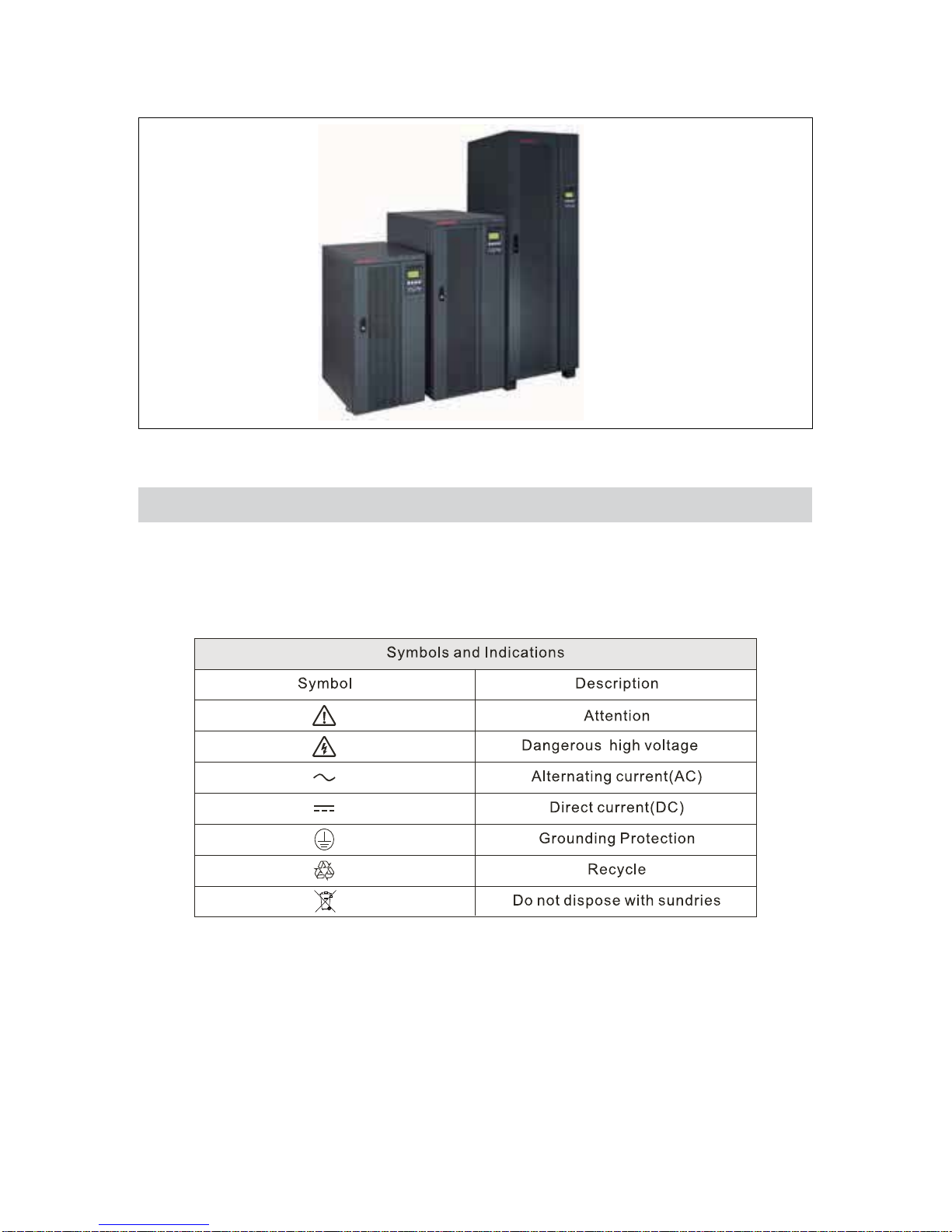
1.1 Product introduction........................................................................................................1
1.2 Frequently used symbols.................................................................................................2
Chapter 2 Exterior appearance.......................................................................3
2.1 Unpacking inspection......................................................................................................3
2.2 Exterior gure..................................................................................................................5
2.3 Panel instructions............................................................................................................6
Chapter 3 Installation instructions...............................................................8
3.1 Installation Notice...........................................................................................................8
3.2 Installation space.............................................................................................................8
3.3 Installation and wiring connection diagram...................................................................10
3.4
Requirements of wiring cables and protect device for Castle EX series UPS
.....................14
3.5 Parallel UPS installation................................................................................................15
3.6 Procedures of connecting battery bank to UPS.............................................................18
Chapter 4 Operation.............................................................................................19
4.1 Single UPS operation.....................................................................................................19
4.2 Parallel UPS operation...................................................................................................26
Chapter 5 Communication Interface..........................................................28
Chapter 6 Optional accessories.........................................................32
6.1 Power Feedback Module...............................................................................................32
6.2 Transformer...................................................................................................................32
6.3 Double Charge Boards...................................................................................................33
6.4 Temperature Sensor.......................................................................................................33
6.5 Dustproof Net...............................................................................................................33
6.6 IP21 Option...................................................................................................................34
Chapter 7 Transportation, Maintenance and Troubleshooting
................35
Appendix 1Techinial parameters and specifications............................37
Appendix 2 Light reference table..........................................................38
Appendix 3 Warranty...................................................................................40

Chapter 1 Brief introduction
1.1 Product introduction
"
pure-online and three phase input and three phase output UPS.This series provides perfect
solution for power source protection and successfully solves problems such as blackout,
$""
&
be widely used in computer equipment, communications equipment and other controlling
equipments, and under the impact of the load for a particular election can be installed
accessories to deal with complex industrial environment. Therefore, Castle EX Series
"
"'
Manifold function of Castle EX series products to provide high-quality power supply
guarantee for your device:
Advanced DSP digital control technology to effectively improve product performance
and system reliability
N + X parallel redundancy ( support sharing batteries in parallel)
Excellent performance of industrial environment protection
Economy and security of ECO mode of operation allows UPS efciency of more than
98%
High-denition LCD interface for human-machine interaction, intuitive and convenient
operation
Powerful communication interface and remote monitoring
Abundant optional accessories, can be exibly congured according to actual demands.
1

2
1.2 Frequently used symbols
The following symbols will be frequently used in this User Manual as well as in the
process of actual application; therefore, correct identication and understanding of their
connotations prove necessary.

Chapter 2 Exterior appearance
2.1 Unpacking inspection
1. Unpack and there should be:
1) UPS
2) Winpower Disc
3) Accessories including user manualǃRoHS card and two keys of the door
2. Check whether the UPS is damaged during the process of transportation or not. Should
any damage be observed or parts be found missing, do not start the machine. Contact the
forwarder and distributor immediately.
1)Remove the top cover plate by unlocking the
wood screws with a sleeve.
2˅Remove the packing cardboards from the
sides of the unit.
3
Note: Make sure that the heights of the door and some other obstacles are
appropriate.

3˅Remove the foam and plastic bag around the
unit.
4˅Move the frame smoothly from the pallet to
the ground or the reserved position for installation
with a forklift.
4
2) For 3C3 EX 60KS/80KS models, remove the iron brackets xing the UPS with
a wrench rstly, then move the frame smoothly from the pallet to the ground, and
x the UPS with the iron brackets again.
Note: 1) 3C3 EX 20KS/30KS/40KS and ISO models
are provided with brake pads, rotate the wrench
(NO.19) clockwise until the brake pad revolves to
the ground, which can prevent the unit from moving.

2.2 Exterior gure
Exterior gure of 3C3 EX 20KS/30KS/40KS UPS
Front view Front view(without front panel)
5
Rear view(3C3 EX 20K) Rear view(3C3 EX 30KS/40KS)

6
Exterior gure of 3C3 EX 60KS/80KS UPS
Front view Front view(without front panel)
top view bottom view
2.3 Panel instructions
The LCD panel is the human-machine interface used to carry
out the visual operations of the UPS, including the power-on,
power-off, status display, fault alarm, parameter setting etc. And
all the operations of the UPS can be realized through the LCD
panel after installing the UPS. It consists of three parts: the LED
indicators, LCD and function keys. Please refer to the table
below for the description of the LED indicators and function
keys.

Status LED Indicator: Display the current UPS operating mode or status.
Identier LED Indicator Color Status
ķAC green UPS is powered directly by AC
ĸInverter green UPS is powering through the inverter
ĹBattery yellow Line input fault, UPS is powering by batteries
ĺBypass green UPS is powering the load by AC through bypass
ĻFault red
LED will solid on with continuous warning tone or ash
with intermission warning tone in case of UPS abnormal
function
LCD display screenüļ˖Display detailed UPS information
Function Keys: selecting and opening menu items, accessing information and changing
system parameters etc.
Identier Key Name Function
ĽConrm/
Enter
Select a menu or conrm an operation; conrm the present
input password letter and enter the next password letter input
process; back to the main menu from the status screen.
ľPage Down Switch to next screen display under the same menu.
ĿƷPage UP Return to last screen display under the same menu.
ŀEsc Escape
Return to previous menu or cancel a certain operation; cancel
the input password; back to the status screen from the main
menu.
7
Note: Please refer to Appendix 2 for detailed information of LED in accordance
with the UPS status.

Chapter 3 Installation instructions
3.1 Installation Notice
1) The installation of Castle EX series products must be performed in compliance with the
electrical code by professional personnel.
2) Install the UPS in a clean and stable environment that is free of vibration, dust, high
humidity, ammable gas, and ammable liquid or caustic substance.
3) To ensure normal UPS performance, ambient temperature should range between 0-40ć.
If temperature exceeds 40ć, maximum load should be decreased progressively by 12%
of the rated amount along with every increase of temperature by 5ć. The maximum am-
bient temperature for normal UPS performance should not exceed 50ć.
4) It is suggested that battery pack should work within a temperature range from15ćto
25ć.
5) Altitude for normal UPS function should not exceed 1000m. Should UPS be intended
for application above 1000m, progressive decrease of rated output should be applied as
listed in the following chart:
Altitude(m) 1000 1500 2000 2500 3000 3500 4000 4500 5000
Derating
coefcient 100ˁ95ˁ91ˁ86ˁ82ˁ78ˁ74ˁ70ˁ67ˁ
3.2 Installation space
3C3 EX 20KS/30KS/40KS series utilizes forced fan cooling and installation spot should
make allowance for ventilation. Meanwhile, inside maintenance should be carried out
from the front side and therefore maintenance space should also be considered in advance.
Refer to the following gure for installation space:
8

3C3 EX 60KS/80KS series adopt the bottom air inlets and top air outlets to ensure good
ventilation, do not put any sundries at the top of the UPS, and the ventilation spacing
above the UPS should be no less than 500mm, otherwise the UPS internal temperature
will rise dramatically. Do not install the UPS under the outtake of an air conditioner,
otherwise, the water may drop into the UPS and thus cause UPS fault or a re. There must
be at least 1000mm of space reserved in front of and behind the UPS for internal and main
power part maintenance,please refer to the gure below for installation space:
9

3C3 EX 20KS/30KS/40KS wiring connection:
1. Wiring connection diagram:
10
3.3 Installation and wiring connection diagram
3C3 EX 20KS/30KS/40KS standard models are integrated with dual power input, and 3C3
EX 60KS/80KS standard models with single power input. The switch between the single
power and dual power supply can be carried out by customer service engineers according
to customerÿs request. All the operations should only be carried out by the technical
personnel of the company or authorized by the company. Do not open the case cover
arbitrarily; otherwise, electric shock may occur.
2. Single power input:
Only connect the AC (34W) to the Main 1.
(1)Ground wire should be connected to the UPS ground terminal;
(2)Connect the AC input cable to the terminal block ķ;
(3)Connect the AC three-phase input lines to the bypass three-phase input lines ĸ
(4)Connect the four load power wires to the terminal block Ĺ

11
Notes:
Please make sure that the input power is three-phase with 4 wires, and the
input voltage is within the allowable voltage range (refer to Appendix 1).
Make sure the input power is the positive phase sequence and battery polarities
are correctly connected.
single power input(34W):20kVA~40kVA connection diagram
For dual power input, the conducting wire between AC input terminal and bypass input
terminal must be removed rstly.
(1) Ground wire should be connected to the UPS ground terminal;
(2) Connect the four AC input wires to the terminal block ķ;
(3) Connect the four bypass input wires to the terminal block ĸ, N lines of the main 1
and main 2 are connected to the same terminal block;
(4) Connect the four load power wires to the terminal block Ĺ
3. Dual power input:
dual power input(34W):20kVA~40kVA connection diagram

Only connect the AC (34W) to the main input terminal.
(1) Ground wire should be connected to the UPS ground terminal;
(2) Connect the AC input cable to the terminal block ķ;
(3) Connect the four load power wires to the terminal block ĸ
3C3 EX 20KS/30KS/40KS wiring connection:
1. Wiring connection diagram:
2. Single power input:
12
Notes:
Please make sure that the input power is three-phase with 4 wires, and the
input voltage is within the allowable voltage range (refer to Appendix 1).
Make sure the input power is the positive phase sequence and battery polarities
are correctly connected.
single power input(34W):60kVA~80kVA connection diagram

13
Notes:
Please make sure that the input power is three-phase with 4 wires, and the
input voltage is within the allowable voltage range (refer to Appendix 1).
Make sure the input power is the positive phase sequence and battery polarities
are correctly connected.
Notes:
Please make sure that the input power is three-phase with 4 wires, and the
input voltage is within the allowable voltage range (refer to Appendix 1).
Make sure the input power is the positive phase sequence and battery polarities
are correctly connected.
3. Dual power input:
Customers may choose the dual power input according to their needs, and the installation
of the bypass input switch is carried out by the customer service engineers.
(1) Ground wire should be connected to the UPS ground terminal;
(2) Connect the AC input cable to the terminal block ķ,and the bypass input wire to the
terminal block ĸ;
(3) Connect the four load power wires to the terminal block Ĺ
dual power input(34W):60kVA~80kVA connection diagram
This manual suits for next models
9
Table of contents
Other Santak UPS manuals

Santak
Santak K Series User manual

Santak
Santak ARRAY User manual

Santak
Santak Castle C6K(E) User manual

Santak
Santak ARRAY 4 User manual

Santak
Santak CASTLE Series User manual

Santak
Santak CASTLE Series User manual

Santak
Santak CASTLE RACK 6K User manual

Santak
Santak CASTLE 20KS User manual

Santak
Santak C1KR(S) User manual

Santak
Santak CASTLE Series User manual