Santak Castle C6K(E) User manual

Uninterruptible Power Systems
CASTLE SERIES
C6K(e) / C6KS(e) / C10K(e) / C10KS(e)
USER MANUAL

Please complywithall warnings
and operating instructionsinthis
manualand on theunitstrictly.
Keepthismanualproperlyforfu-
turereference.Donotoperate
thisunituntil reading through all
safetyinformation and operating
instructionscarefully.

TableofContents
1.Briefintroduction
1.1Systemand modeldescription
1.2Description ofcommonlyused symbols
1.3Appearance
1.4Productspecification and performance
Generalspecification
Operating environment
2.Installation
2.1Unpacking and Inspection
2.2Inputand outputpowerwiring and protectiveearthinstallation
2.3Operating procedureforconnecting the long backup timemodelUPS
3.Operation and operating mode
3.1Operation
3.2Operating mode
4.Batterymaintenance
5.Notes forbatterydisposaland batteryreplacement
6.Troubleshooting
Appendix1Display panel
Appendix2Thecorresponding form oftheLEDdisplay
Appendix3Warranty
withthe externalbattery
1
1
2
3
4
4
6
8
9
14
15
16
18
19
21

1
ThisOnline Seriesisan uninterruptiblepowersystemincorporating
double-conversion technology.It providesperfectprotection specifi-
callyforcomputerequipment, Communication Systemsand com-
puterized instruments.
Itstrue online double-conversion design eliminatesall mainspower
disturbances.Arectifierconvertsthe alternating currentfromthe util-
itypowertodirectcurrent. Thisdirectcurrentchargesthe batteries
and powersthe inverter.Onthe basisofthisDC voltage,the inverter
generatesapuresinusoidalACvoltage,whichisconstantlypower-
ing the loads.Computersand Peripheralsconnected tothe UPS
thusentirelypower-protected.Inthe eventofmainsfailure,the main-
tenance-free batteriespowerthe inverter.
Thismanualisapplicabletothe following models:
1.1Systemand modeldescription
1.Briefintroduction
1)The C6K(e)isastandardmodelwithinbuiltbattery;
2)The C6KS(e)isalong backup timemodel,whichisableto
connectwiththe externalbatterybank;
3)The C10K(e)isastandardmodelwithinbuiltbattery;
4)The C10KS(e)isalong backup timemodel,whichisableto
connectwiththe externalbatterybank;
1.2Description ofcommonlyusedsymbols
The following symbolswill be used inthismanualand mayappear
during the courseofyourpracticalapplications.Therefore,all users
shouldbe familiarwiththemand understand theirmeanings.
Directcurrentsource(DC)
Donotdisposewithordinarytrash
Notation and Explanation
Notation Notation
Explanation Explanation
Alertyoutopayspecialattention
Cautionofhighvoltage
TurnontheUPS
Turnoff theUPS
Idleorshutdownthe UPS
Alternatingcurrentsource(AC)
Protectiveground
Alarm silence
Overloadindication
Batterycheck
Recyclable

2
1.3Appearance
RS232
Fan
Inputbreaker
TBcover
Terminal
Block
Intelligentslot
Externalbattery
Cabletying
BACKVIEWofC6K(e)/C6KS(e)
RS232
Fan
Inputbreaker
TBcover
TerminalBlock
Intelligentslot
Externalbattery
socket
Cabletying
BACKVIEWofC10K(e)/C10KS(e)
socket
1.Briefintroduction

3
1.4Productspecification and performance
Generalspecification
50
(176-276)VAC
31Amax.
46Hz~54Hz
>0.98(Full load)
240VDC
24Amax.
220VAC
27A
50
(176-276)VAC
31Amax.
46Hz~54Hz
>0.98(Full load)
240VDC
24Amax.
220VAC
27A
1%
0.7lag
50
(176-276)VAC
50Amax.
46Hz~54Hz
>0.98(Full load)
240VDC
40Amax.
220VAC
45A
50
(176-276)VAC
50Amax.
46Hz~54Hz
>0.98(Full load)
240VDC
40Amax.
220VAC
45A
Voltage
Current
Frequency
PowerFactor
Voltage
Current
Voltege
Current
Voltage regulation
PowerFactor
Distortion
Overload capacity
Input
Battery
Output
Model
PowerRating
Frequency (Hz)
1.Briefintroduction
6kVA/4.2kW6kVA/4.2kW10kVA/7kW10kVA/7kW
C6K(e)C6KS(e)C10K(e)C10KS(e)
105%-130%load transferstobypass modeafter10minutes
>130%loadtransferstobypassmodeafter1secondandshutdown
theoutputafter1minute
±
Synchronized 46-54HzinLine mode(ACmode)
0.1%ofnormalfrequencyinBatterymode
±
Frequency tolerance
THD<2%Fullload (Linearload)
Currentcrestratio3:1maximum
Operating environment
<95%<1000m
Temperature
0-40
℃℃
HumidityAltitude Storage temperature
0-40
℃℃
Note:If the UPS isinstalled oruesdinaplacewherethe altitude isabovethan 1000m,the
outputpowermustbe derated inuse,pleaserefertothe following:
Altitude (M)
Deratingpower
1000 1500 2000 2500 3000 3500 4000 4500
100% 95% 91% 86% 82%
5000
78% 74% 70% 67%

4
2.1Unpacking and inspection
1.Notes forinstallation
1)The UPS mustbe installed inalocation withgood ventilation,far
awayfromwater,inflammablegasand corrosiveagents.
2)Ensurethe airventson the frontand rearofthe UPS arenotblocked.
Allowatleast0.5mofspaceon eachside.
3)Condensation towaterdropsmayoccurifthe UPS isunpacked ina
verylowtemperatureenvironment. Inthiscaseitisnecessaryto
waituntil the UPS isfullydried inside outbeforeproceeding instal-
lation and use.Otherwisetherearehazardsofelectricshock.
2.Installation
Installation and wiring mustbe performed inaccordancewiththe local
electriccode and the following instructionsbyprofessionalpersonnel.
Forsafety,pleasecutoff the mainspowerbreakerbeforeinstallation.
The batterybreakeralsoneedstobe cutoff ifitisalong backup time
model(“S”model).
1)Open the terminalblock coverlocated on the rearpanelofthe UPS,
pleaserefertothe appearancediagram.
2)ForC6K(e)/C6KS(e)UPS,itisrecommended toselectthe UL1015
10AWG(6mm2)wireorotherinsulated wirewhichcomplieswith
AWGStandardforthe UPS inputand outputwirings.
1)Unpack the packaging and check the package contents.The ship-
ping package contains:
AUPS
Ausermanual
Acommunication cable
Abatterycable(forC6KS(e)/C10KS(e))
2)Inspectthe appearanceofthe UPS tosee ifthereisanydamage
during transportation.Donotturnon the unitand notifythe carrier
and dealerimmediatelyifthereisanydamage orlacking ofsome
parts.
2.2Inputand outputpowerwiring and protective earth
ground installation
2.Installation

5
3)ForC10K(e)/C10KS(e)UPS,itisrecommended toselectthe UL1015
8AWG(10mm2)wireorotherinsulated wirewhichcomplieswith
AWGStandardforthe UPS inputand outputwirings.
Note:Donotusethe wall receptacleasthe inputpowersourceforthe
UPS,asitsrated currentisless than the UPS’s maximuminput
current. Otherwisethe receptaclemaybe burned and destroyed.
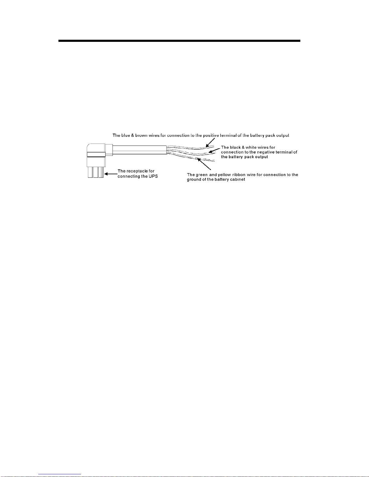
4)Connectthe inputand outputwirestothe corresponding inputand
outputterminalsaccording tothe following diagram.
Note:you mustmakesurethatthe inputand outputwiresand the input
and outputterminalsareconnected tightly.
5)The protectiveearthground wirereferstothe wireconnection be-
tween the equipmentwhichconsumeselectro-equipmentand the
ground wire.The wirediameterofprotectiveearthground wireshould
be atleastasabovementioned foreachmodeland green wireor
green wirewithyellowribbon wireisused.
6)
7)Pleaseinstall the leakcurrentprotectivebreakeratthe outputpower
distribution panelofthe UPS ifnecessary.
8)Toconnectthe load withthe UPS,pleaseturnoff all the loadsfirst,
then perform the connection and finallyturnon the loadsone byone.
9)Nomatterthe UPS isconnected tothe utilitypowerornot, the output
ofthe UPS mayhaveelectricity.The partsinside the unitmaystill
havehazardousvoltage afterturning off the UPS.Tomakethe UPS
haveno output, poweroff the UPS,and then disconnectthe utility
powersupply.
10)Suggestcharging the batteriesfor8hoursbeforeuse.After
connection,turnthe inputbreakerinthe “ON”position,the UPS will
charge the batteriesautomatically.You can alsousethe UPS im-
mediatelywithoutcharging the batteriesfirst, butthe backup time
maybe less than the standardvalue.
11)If itisnecessarytoconnectthe inductanceload suchasamonitor
oralaserprintertothe UPS,the start-up powershouldbe used for
calculating the capacityofthe UPS,asitsstart-up powerconsump-
tion istoo bigwhen itisstarted.
Afterhaving completed the installation,makesurethe wiring iscorrect.
2.Installation

6
2.3
1.The nominalDC voltage ofexternalbatterypack is240VDC.Each
batterypack consistsof20 piecesof12Vmaintenancefree batter-
iesinseries.Toachievelongerbackup time,itispossibletocon-
nectmulti-batterypacks,butthe principleof“samevoltage,same
type”shouldbe strictlyfollowed.
2.The connectorofthe externalbatterycableisused toplug intothe
externalbatterysocketofthe UPS,the otherend ofthe external
batterycableismade ofthree open wireswithring terminalsto
connectwiththe externalbatterypack(s).The procedureof
installatiing batterybankshouldbe complied withstrictly.
Operating procedureforconnecting thelong backup timemodel
UPS withtheexternalbattery
Otherwiseyou mayencounterthe hazardousofelectricshock.
1)ADC breakermustbe connected between the batterypack and
the UPS.The capacityofbreakermustbe notless than the data
specified inthe generalspecification.
2)Setthe batterypack breakerin“OFF”position and connectthe 20
piecesofbatteriesinseries.
3)You mustconnectthe externalbatterycabletothe batteryfirst, if
you connectthe cabletothe UPS first, you mayencounterthe
hazardousofelectricshock.The positivepoleofthe batteryis
connected tothe C10KS(e)inparallelwithblue and brownwires;
the negativepoleofthe batteryisconnected tothe C10KS(e)in
parallelwithblack and whitewires;the green and yellowribbon
wireisconnected tothe ground ofthe batterycabinet.
InputandOutputTerminalBlock wiring
diagramofC6K(e)/C6KS(e)C10K(e)/C10KS(e)
2.Installation

7
2.Installation
3.Tocompletethe connection byplugging the connectorofthe external
batterycableintothe externalbatterysocketofthe UPS.Donot
attempttoconnectanyloadstothe UPS now.You shouldconnect
the inputpowerwiretothe rightposition first.And then setthe breaker
ofthe batterypack inthe “ON”position.Afterthatsetthe inputbreaker
inthe “ON”position.The UPS beginstocharge the batterypacks at
the time.
The externalbatterycablediagramforC6KS(e)/C10KS(e)
(The cablemayvaryfromdifferent“S”models)

8
It iseasy tooperatethe equipment, withno previoustraining.You justneed to
read through thismanualand operateaccording tothe instructionsinit. The
meaning ofthe LEDindicators,pleaserefertothe appendix1“Displaypanel”.
3.1Operation
1.Turnon theUPS withutilitypowersupplied(inLinemode/AC
mode)
1)Afteryou makesurethatthe powersupplyconnection iscorrect,
setthe inputbreakerinthe “ON”position first. Atthistimethe fan
rotatesand the UPS suppliespowertothe load viathe bypass.
The UPS operatesinBypass mode.
2)Topoweron the UPS bysimplypressing the “ON”button continu-
ouslyformorethan 1second.
3)When being powered on,the UPS will perform self-diagnosis,
withthe load/batterylevelLEDsturned on and then off one after
anotherinascending order.Afewsecondslater,the INVLEDis
turned on,the UPS isalreadyrunning inUtilityPowermode.If the
utilitypowerisabnormal,the UPS will operateinbatterymode
withoutoutputinterruption ofthe UPS.
2.Turnon theUPS withno utilitypowersupplied(inBatterymode)
3.Turnoff theUPS withutilitypowersupplied(inLinemode/AC
mode)
1)Press the “ON”button continuouslyformorethan 1second to
poweron the UPS.Forlong back up timemodel(“S”model),
pleasemakesurethatthe batterybreakerisin“ON”position.
2)During the courseofstarting up,the UPS hasthe sameaction as
ifitisconnected toutilitypowerexceptthatthe utilitypowerLED
isnotturned on and the batteryLEDisturned on instead.
1)Press the “OFF”button continuouslyformorethan 1second to
turnoff the inverterofthe UPS immediately.
2)When being powered off, the UPS will perform self-diagnosis,
the Load/BatterylevelLEDswill be turned on and then off one
afteranotherinascending order,then the INVLEDwill be turned
off and Bypass LEDwill be turned on.The UPS isworking in
Bypass mode.
3)Upon completion ofthe abovetoturnitoff, outputofelectric
currentofthe UPS isstill present. Inordertocutoff the output
3.Operation and Operating mode

9
4.Turnoff theUPS withno utilitypowersupplied(inBatterymode)
fromthe UPS,simplycutoff the utilitypowersupplyand the UPS
will perform self-diagnosis,finallynotanydisplayisshownon
the displaypaneland no voltage outputisavailablefromthe
UPS output.
1)Press the “OFF”button continuouslyformorethan 1second to
poweroff the UPS.
2)When being powered off, the UPS will perform self-diagnosis,
the Load/BatterylevelLEDswill be turned on and then off one
afteranotherinascending order.Finallynotanydisplayisshown
on the displaypaneland no voltage isavailablefromthe UPS
output.
Suggestions:
1.Utilitypowermode
3.2Operating mode
Fig3-1The utilitypowermode
The displaypanelinutilitypowermode isshowninthe following
diagram.The utilitypowerLEDand the INVLEDareturned on.The
load levelLEDswill be turnd on inaccordancewiththe load capacity
connected.
1)If the batteryLEDisturned on and the utilitypowerLEDflashes,it
indicatesthe voltage orfrequency ofthe utilitypowerhasex-
ceeded the normalrange,the UPS operatesinbatterymode.
2)If outputoverloaded,the load levelLEDswill be turned on and
alarm will keep twiceeverysecond.You shouldgetridofsome
unnecessaryloadsone byone todecreasethe loadsconnected
tothe UPS less than 90%ofitsnominalpowercapacity.
3.Operation and Operating mode
Pleaseturnoff the connected loadsbeforeturning on
the UPS and turnon the loadsone byone afterthe
UPS isworking inINVmode.Turnoff all ofthe con-
nected loadsbeforeturning off the UPS.

10
Note:Pleasefollowthe following stepstoconnectthe generator:
Activatethe generatorand waituntil the operation isstable
beforesupplying powerofthe generatortothe UPS (be
surethatthe UPS isinidlemode).Then turnon the UPS
according tothe start-up procedure.Afterthe UPS isturned
on,then the loadscan be connected tothe UPS one by
one.
The powercapacityofthe ACgeneratorshouldbe atleast
twiceofthe UPS capacity.
2.Batterymode
The displaypanelinbatterymode isshowninthe following dia-
gramFig.3-2.The batteryLEDand the INVLEDareturned on.The
displayed numberofthe batterylevelLEDswill be turned on in
accordancewiththe batterycapacity.Notethatthe load levelLEDs
inutilitypowermode will indicatethe levelofthe batterycapacityin
batterymode instead.
1)When the UPS isrunning inbatterymode,the buzzerbeepsonce
every4seconds.If the “ON”button on the frontpanelispressed
formorethan 1second again,the buzzerwill stop beeping (in
silencemode).Press the “ON”button onceagainformorethan
1second toresumethe alarm function.
Fig3-2Batterymode diagram
2)When the batterycapacitydecreases,the numberofthe battery
capacityLEDsturned on will be reduced.If the batteryvoltage
descendstothe alarm level,the buzzerwill beep onceevery
second toremind usersofinsufficientbatterycapacityand the
UPS issoon going toshutdownautomatically.Then the load
operationsshouldbe carried outpromptlyand the loadsshould
be eliminated one byone.
3.Operation and Operating mode

11
3.Bypass mode
The displaypanelinbypass mode isshowninthe following dia-
gramFig.3-3.The utilitypowerLEDand the bypass LEDarelit. The
displayed numberofthe load LEDswill be turned on inaccordance
withthe load capacityconnected.The UPS will beep onceevery2
minutesinbypass mode.
1)The utilitypowerLEDflashes,itshowsthatthe voltage orfre-
quency ofthe utilitypowerhasexceeded the normalrange ofthe
UPS.
2)Otherindicationson the displaypanelarethe sameinutilitymode.
3)The UPS doesnothavethe backup function when itisinbypass
mode.The powerused bythe load issupplied fromthe utility
powerviainternalfilter.
4.Abnormalitymode
Incasethe faultLEDisturned on when the UPS isinuse,itshows
thatthe UPS isoperating inabnormalmode.Pleaserefertothe
troubleshooting insection 6fordetails.
3.Operation and Operating mode
Fig3-3UPS bypass mode diagram

12
5.Backup timeforthestandardmodel
The backup timeofthe long backup timemodelisdependenton
the externalbatterypack capacityand the load levelaswell asother
factors.
The backup timeofstandardmodelmayvaryfromdifferentmodels
and load level.Pleaserefertothe following:
Discharging Time (min)
Load level
backup timeofC6k(e)Load level
backup timeofC10k(e)
3.Operation and Operating mode

13
Intelligentslot
Thisseriesisequipped withan intelligentslotforWebpower(optional
accessory)orotheroptionalcardtoachieveremotemanagementof
the UPS through internet/intranet. Pleasecontactyourlocaldistribu-
torforfurtherinformation.
RS232 interface
1)The following arethe descriptionsand pinassignmentofRS232
DB-9port:
Baud rate:2400bps
Databit: 8bit
Ending bit:1bit
Paritybit: None
RS232 Interface
pinnumber
3
2
5
Function description
Rx
Tx
Ground
I/O
Input
Output
Ground
OptionalAS400 interface
ThisoptionalAS400 cardprovidesdrycontactclosuresignal“OPEN”
or“CLOSE”.Following arethe pinassignmentand the descriptionsof
AS400 card:
PIN1:UPS failure(normallyopen,activeclose)
PIN2:summaryalarm
PIN3:ground
PIN4:Remoteshutdown
PIN5:Common
PIN6:Bypass active(relayclose)
PIN7:Batterylow
PIN8:UPS On(relayclose)
PIN9:UtilityPowerfailure(normallyopen,activeclose)
DB-9pinassignment:
6.Communication Interface
AS400 Interface
3.Operation and Operating mode

14
4.Batterymaintenance
ThisseriesUPS onlyrequiresminimalmaintenance.The batteryused
forstandardmodelsarevalveregulated sealed lead-acidmaintenance
free battery.Thesemodelsrequireminimalrepairs.The onlyrequire-
mentistocharge the UPS regularlyinordertomaximizethe expected
lifeofthe battery.When being connected tothe utilitypower,whetherthe
UPS isturned on ornot, the UPS keepscharging the batteriesand also
offersthe protectivefunction ofovercharging and overdischarging.
The UPS shouldbe charged onceevery4to6monthsifithasnotbeen
used foralong time.
Inthe regionsofhotclimates,the batteryshouldbe charged and dis-
charged every2months.The standardcharging timeshouldbe atleast
12 hours.
Undernormalconditions,the batterylifelasts3to5years.Incaseifthe
batteryisfound notingood condition,earlierreplacementshouldbe
made.Batteryreplacementshouldbe performed byqualified personnel.
Replacebatterieswiththe samenumberand sametype ofbatteries.
Donotreplacethe batteryindividually.All the batteriesshouldbe re-
placed atthe sametimefollowing the instructionsofthe batterysupplier.
Normally,the batteriesshouldbe charged and discharged onceevery
4to6months.Charging shouldbeginafterthe UPS shutsdownauto-
maticallyinthe courseofdischarging,the standardcharging timefor
the standardUPS shouldbe atleast12 hours.

15
1)Beforedisposing ofbatteries,removeconductivejewelrysuchasnecklace,
wristwatchesand rings.
2)If itisnecessarytoreplaceanyconnection cables,pleasepurchasethe
originalmaterialsfromthe authorized distributorsorservicecenters,so
astoavoidoverheatorsparkresulting infiredue toinsufficientcapacity.
3)Donotdisposeofbatteriesorbatterypacks inafire,theymayexplode.
4)Donotopen ormutilatebatteries,released electrolyteishighlypoisonous
and harmfultothe skinand eyes.
5)Donotshortthe positiveand negativeofthe batteryelectrode,otherwise,it
mayresultinelectricshock orfire.
6)Makesurethatthereisno voltage beforetouching the batteries.The bat-
terycircuitisnotisolated fromthe inputpotentialcircuit. Theremaybe
hazardousvoltage between the batteryterminalsand the ground.
7)Even though the inputbreakerisdisconnected,the componentsinside the
UPS arestill connected withthe batteries,and therearepotentialhazard-
ousvoltages.Therefore,beforeanymaintenanceand repairsworkiscar-
ried out, switchoff the breakerofthe batterypack ordisconnectthe jumper
wireofconnecting between the batteries.
8)Batteriescontainhazardousvoltage and current. Batterymaintenancesuch
asthe batteryreplacementmustbe carried outbyqualified personnelwho
areknowledgeableaboutbatteries.Nootherpersonsshouldhandlethe
batteries.
5.Notes forbatterydisposaland batteryreplacement

16
6.Troubleshooting
Makesurethe UPS isnotoverloaded;
the airventsarenotblocked and the
ambienttemperatureisnottoo high.
Waitfor10 minutesforthe UPS to
cooldownbeforeturning on again.If
failed,pleasecontactthedistributor
orservicecenter.
ProblemPossiblecause Solution
The #1 FaultLEDand the
#6 LEDareturned on,the
buzzerbeepscontinuously
The UPS shutdowndue
tointernaloverheat
Pleasecontactthe distributor
orservicecenter.
Check the loadsand removeall non-
criticalequipment. Recalculatethe load
powerand reducethe numberofloads
connected tothe UPS.Check thatthe
loadsarenotfailed.
The UPS isrunning inbatterymode.To
saveyourdataand closethe applica-
tionprogram.Makesurethe utilitypower
iswithinthe inputvoltage orfrequency
range permitted bythe UPS.
Pleasecontactthe distributororser-
vicecenter.
Pleasecontactthe distributororser-
vicecenter.
Turnoff the UPS.Removeall the
loads.Ensurethattheload isnotfailed
orthe UPS hasno internalfaults
beforeturning iton again.If failed,
pleasecontactthe distributororser-
vicecenter.
The chargerofthe UPS
isdefective.
The UPS isoverloaded
orthe load equipmentis
faulty
The voltage orfre-
quency ofthe utility
powerisoutofthe input
range ofthe UPS.
The UPS shutsdown
due toitsinternalfault.
The UPS shutsdown
due toitsinternalfault.
The UPS outputis
shortcircuited.
The #1 FaultLEDand the
batteryLEDareturned on,
the buzzerbeepseverysec-
ond
The #1 FaultLEDand the
#2 LEDareturned on,the
UPS beepscontinuously
The utilitypowerLED
flashes
The #1 FaultLEDand the #5
LEDareturned on,the UPS
beepscontinuously
The #1 FaultLEDand the
#4 LEDareturned on,the
UPS beepscontinuously
The #1 FaultLEDand the #2
and #5 LEDareturned on,
and the buzzerbeepscon-
tinuously

17
The UPS cannotpoweron
afterpressing the “ON”but-
ton
ProblemPossiblecause Solution
BatteryLEDflashes
The utilitypowerisnormal,
butthe UPS can notturnin
line mode
Batterydischarging time
diminishes
Batteryloworbatterynot
connected
UPS fault
The UPS isnotcon-
nected tothe batteryor
the batterypack volt-
age istoo low.
The “ON”button is
pressed too briefly
Batteryaged
UPS overloaded
Batterynotyetbeen
fullycharged
Check the battery.If the batteryis
damaged,replacethe batteryimmedi-
atelyand ensurethatthe batterybreaker
isin“ON”position.
ACinputbreakerin
“OFF”position
Pleasecontactthe distributororser-
vicecenter.
Check the batteryorrecharge the
battery.
Press the “ON”button formorethan 1
second.
Replacethe batteries.Pleasecontact
the distributortoobtainthe partsand
replacementservice.
Check the loadsand removethe non-
criticalequipment.
Keep UPS connected toutilitypower
persistentlyformorethan 10 hoursto
recharge the batteriesagain.
Setthe inputbreakerin“ON”position.
When you contactthe servicecenter,pleaseprovide the following information:
ModelNo.and the serialNo.ofthe UPS;
The datewhen the problemarose;
Completedescription ofthe problem,including the LEDdisplay,alarm
6.Troubleshooting
timemodel,you mayalsoprovide the batteryinformation.
warning,and powercondition and load capacity.If yourUPS isalong backup
This manual suits for next models
3
Table of contents
Other Santak UPS manuals

Santak
Santak C1K User manual

Santak
Santak CASTLE Series User manual

Santak
Santak CASTLE RACK 6K User manual

Santak
Santak CASTLE On-Line Series User manual

Santak
Santak C1KR(S) User manual

Santak
Santak CASTLE Series User manual

Santak
Santak ARRAY User manual

Santak
Santak CASTLE 20KS User manual

Santak
Santak K Series User manual

Santak
Santak 3C3 EX 30KS User manual