manuals.online logo
Brands
  1. Home
  2. •
  3. Brands
  4. •
  5. Santon
  6. •
  7. Water Heater
  8. •
  9. Santon A7/3 Guide

Santon A7/3 Guide

10. GUARANTEE
This product is guaranteed against faulty materials and manufacture for a period of 2 years from the
date of purchase provided that:
1. The unit has been installed in accordance with the Installation and User Instructions
and all relevant Codes of Practice and Regulations in force at the time of Installation, and
that all necessary controls and safety valves have been fitted correctly.
2. Any valves and controls are of the Santon recommended type and specification.
3. The unit has not been modified or tampered with in any way, and has been regularly
maintained as detailed in the Installation and User Instructions.
4. The unit has been used only for heating potable water.
The unit is not guaranteed against damage by frost, and the inner container with integral
immersion heater is not guaranteed against excessive scale build-up.
This Guarantee in no way affects the statutory rights of the consumer.
The policy of Santon is one of continuous product development and, as such, we reserve the right
to change specifications without notice.
11. ENVIRONMENTAL INFORMATION
Santon products are manufactured from many recyclable materials.
At the end of their useful life they should be disposed of at a Local Authority Recycling Centre in
order to realise the full environmental benefits.
Insulation is by means of CFC-free polyurethane foam.
9. SPARE PARTS
In the unlikely event of your Water Heater developing a fault, the following spare parts are
avaliable:
Element plate assembly 1.2kW 95 606 934
Element plate assembly 3kW 95 606 763
Element plate assembly gasket (pk of ten) 95 611 708
Over temperature cut-out 95 612 688
Capillary thermostat 95 612 667
Control valve 95 605 857
Spout adaptor 95 604 677
Spout (12”) complete with adaptor 95 604 678
Top cover moulding 95 614 272
Terminal cover 95 614 273
Sales Tel: (01603) 420130
Sales Fax: (01603) 420149
Hurricane Way, Sales Email: [email protected]
Norwich, Service Tel: (01603) 420347
Norfolk, NR6 6EA. Service Fax: (01603) 420349
www.santon.co.uk Service Email: [email protected]
A member of Baxi Group Ltd.
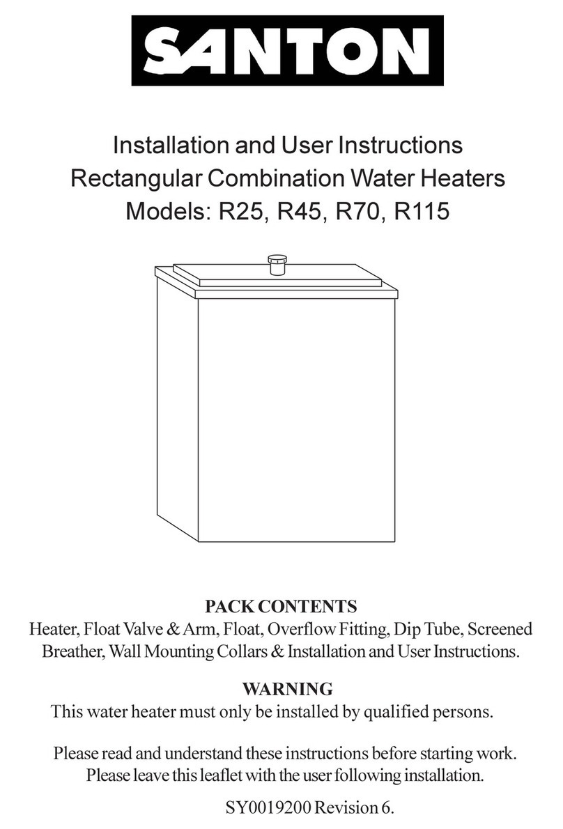
Installation and User Instructions
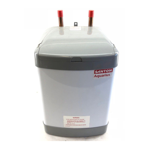
Aquarius Oversink Vented Water Heaters
Models: A7/3, A7/1, A10/3, A10/1.
Please read and understand these instructions before starting work.
Please leave this leaflet with the user following installation
36005792 Issue 2.
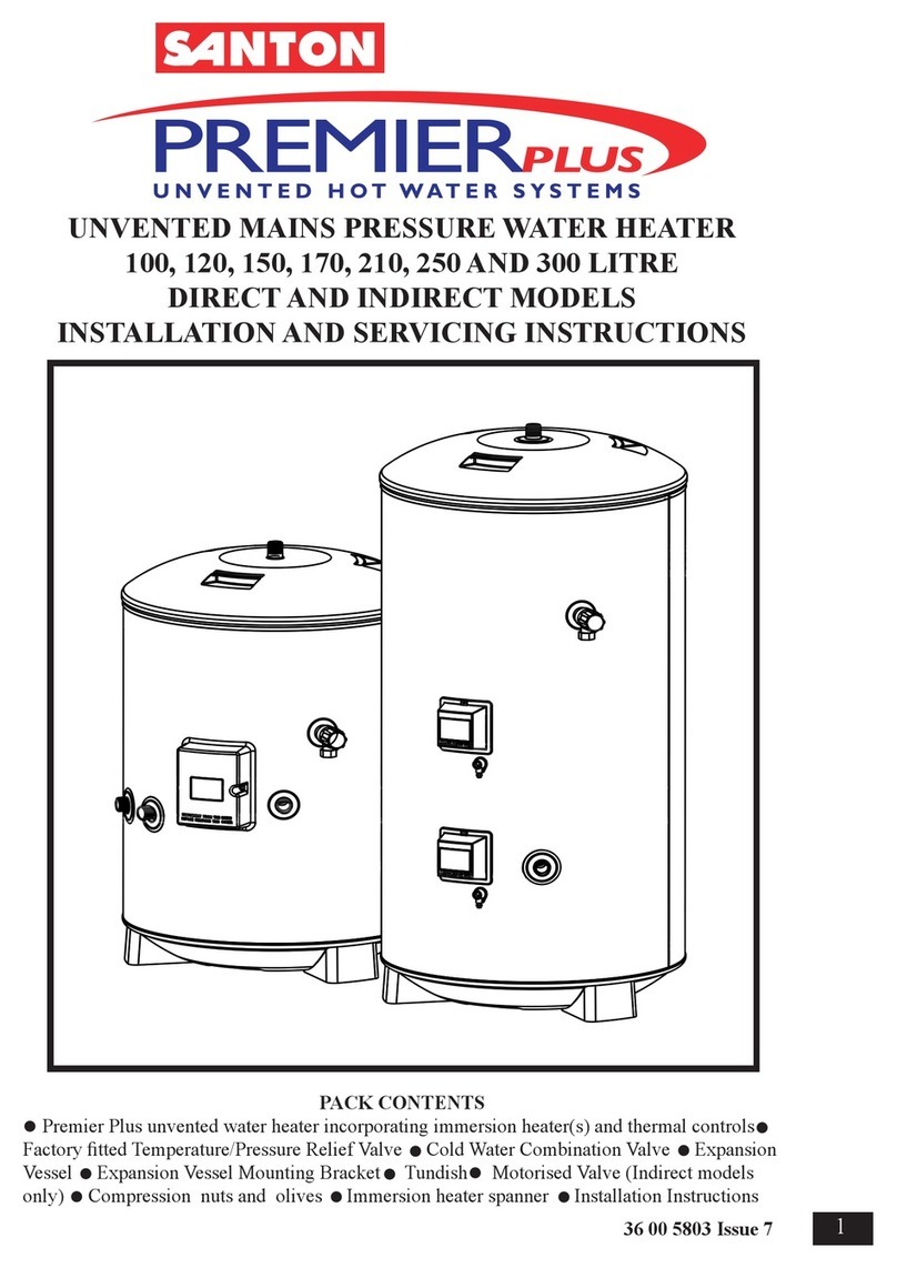
PACK CONTENTS
Heater, Fixing screws and plugs,Spout, Valve
Installation and User Instructions.
WARNING
This water heater must only be installed by qualified persons.
8. FAULT FINDING
SYMPTOM PROBABLE CAUSE ACTION
No hot water 1. Check power Check and replace as necessary.
2. Faulty cut out
3. Faulty thermostat
4. Faulty element
Water too hot 1. Thermostat set to Adjust thermostat.
/cold wrong temperature
2. Faulty thermostat Switch off, check and replace.
No water flow 1. Frozen Switch off electrical power and
allow to thaw at room temperature.
Do not switch on again until full water
flow restored and full checks made for
leaks and electrical safety.
2. No mains supply Check mains.
Continuous water Faulty valve/tap Check and replace.
flow
240
FIXING HOLE
240
57
105
120
X
Y
140
COLD WATER INLET VALVE
2 KEYHOLE
FIXING SLOTS
6mm WIDE
300
DIMENSION X Y
7 LITRE 356 349
10 LITRE 442 435
FIGURE 3 : DIMENSIONS
100
1. INSTALLATION
1. Inlet must always be on the right.
2. The outlet of this water heater acts as a vent and must not be blocked or restricted
in any way.
3. Use only Santon open outlet spouts.
2. POSITIONING THE WATER HEATER
1. Select a suitable site but check that:
a) There is enough clearance under the heater to allow removal of the element
plate (210mm).
b) When using the outlet spout, it will swing over the sink (or sinks) to be supplied.
c) There are no hidden services where the wall is to be drilled.
2. Mark the position of the fixing holes (as shown in Fig. Three).
3. Drill and plug the hole positions.
4. Screw in the top two screws leaving heads 3mm from the wall.
5. Hang the heater on the two top screws.
6. Screw in bottom screw to secure heater.
3. PLUMBING REQUIREMENTS
The water heater is designed to be connected directly to the mains via the valve provided.
It is recommended that a WRAS listed isolating valve (not supplied) be fitted in the water
supply pipe to the heater to allow for servicing.
4. REMOVAL AND FITTING OF TERMINAL COVER
To remove the terminal cover use a large flat bladed screwdriver to relieve the snaps located
towards the front of the terminal cover at either side. Gripping the cover at the front, pull
downwards.
To fit the cover, locate the hinge at the back. Slide the snaps into place. Apply pressure to the
front of the cover pushing it backarwds and upwards until it snaps securely in place.
5. SPOUT AND VALVE
1. Connect the control valve supplied to the inlet pipe on the water heater.
2. Connect the cold water main to the control valve using 15mm outside diameter pipe (either
copper to BS EN 1057 or stainless steel to BS 4127).
3. Push the outlet spout directly into the outlet fitting.
TO REMOVE OUTLET SPOUT
1. Remove terminal cover.
2. Push white ring upwards towards body of fitting.
3. Pull spout downwards.
ELECTRICALEMENTS
6. ELECTRICAL REQUIREMENTS (REFER TO FIGURE 2 - WIRING DIAGRAMS)
·WARNING: THIS APPLIANCE MUST BE EARTHED.
·CONNECT ONLYTO 230 / 240VAC SUPPLY.
·NOMINALCROSS SECTION OF SUPPLY CABLE MUST BEAT LEAST 1.5mm2.
·ADOUBLE POLE ISOLATING SWITCH WITHACONTACT SEPARATION OFAT
LEAST3mm IN EACH POLE MUST BE INCORPORATED IN THE SUPPLY.
·ELECTRICALINSTALLATION MUST CONFORM TO THE CURRENT I.E.E. WIRING
REGULATIONS.
1. Remove terminal cover.
2. Strip the outer sheath and insulation on the cable to the required lengths, making sure the outer
sheath of the cable will be held in the cable grip when the connections are made.
3. Loosen the top screws securing the cable grip.
4. Pass the cable underneath the cable grip and through the top moulding.
5. Make the connections to the terminal block as follows:
-Live (brown or red wire) to terminal marked “L”
-Neutral (blue or black wire) to terminal marked “N”
-Earth (green or green/yellow wire) to terminal marked .
6. Secure the cable in the cable grip by tightening the two screws.
7. Set the adjustable thermostat by rotating the control to the required temperature.
It is recommended that it is set to lowest acceptable temperature to meet user requirements.
This will minimise the risk of scalding and reduce the level of scaling in hard water areas.
8. Replace terminal cover.
7. OPERATION
DO NOT SWITCH ON HEATER UNTIL IT IS FILLED WITH WATER
1. Fill with water by opening valve and leaving open until a full bore of water flows from the
outlet.
2. Close valve and switch on water heater at double pole isolating switch. The heater will heat
water to the temperature set on the thermostat.
3. Check water is heating correctly.
7 litre 1.2kW - after 10 mins water temperature will increase by 20°C -after10 mins water te
7 litre 3kW - after 10 mins water temperature will increase by 60°C
10 litre 1.2kW - after 10 mins water temperature will increase by 15°C
10 litre 3kW - after 10 mins water temperature will increase by 40°C
4. Pass instruction leaflet to user and draw his attention to the following two statements:
a) DO NOT USE HEATER IF THE WATER IS THOUGHT TO BE FROZEN
Switch off immediately at the isolating switch if the water does not flow freely.
Any damage resulting from freezing will not be covered by the guarantee.
b) DURING HEATING THE SPOUT WILLDRIP
This is due to the expansion of water inside the heater and is normal for heaters of this type. It
does not indicate that the valve is faulty and overtightening of the valve can result in damage.
RED WIRE
BLACK WIRE
GREEN/YELLOW
WIRE
ELEMENT
THERMAL FUSE
THERMOSTAT
TERMINAL BLOCK
DOUBLE POLE
ISOLATING SWITCH
BROWN
BLUE
GREEN/YELLOW
MAINS SUPPLY
L
N
FIGURE 2: WIRING DIAGRAM 'AC' ONLY.
OUTLET
INLET CABLE CLAMP
TERMINAL BLOCK
EARTH POST
ELEMENT
THERMOSTAT CONTROL
FIGURE 1: INTERNAL LAYOUT
DRAIN PLUG
THERMAL CUT-OUT
CAPILLARY STAT

This manual suits for next models

3

Other Santon Water Heater manuals

Santon PremierPlus 100 User guide

Santon

Santon PremierPlus 100 User guide

Santon PREMIER PLUS User guide

Santon

Santon PREMIER PLUS User guide

Santon R25 Guide

Santon

Santon R25 Guide

Santon SP2.5 Guide

Santon

Santon SP2.5 Guide

Santon PP100E User guide

Santon

Santon PP100E User guide

Santon Aqualine ALK02 User manual

Santon

Santon Aqualine ALK02 User manual

Santon Premier Plus 120 User guide

Santon

Santon Premier Plus 120 User guide

Santon AL07/3 Guide

Santon

Santon AL07/3 Guide

Santon Aquaheat AH30V Guide

Santon

Santon Aquaheat AH30V Guide

Santon PowerPack User manual

Santon

Santon PowerPack User manual

Santon AH7/2.2 Guide

Santon

Santon AH7/2.2 Guide

Santon Aquarius AU7/3 Guide

Santon

Santon Aquarius AU7/3 Guide

Santon Aquarius AU7/3 Guide

Santon

Santon Aquarius AU7/3 Guide

Santon Aquarius A7/3 Guide

Santon

Santon Aquarius A7/3 Guide

Santon Aquaheat SS V 100 Guide

Santon

Santon Aquaheat SS V 100 Guide

Santon PES170D User guide

Santon

Santon PES170D User guide

Santon EV 2008 Guide

Santon

Santon EV 2008 Guide

Santon PremierPlus User guide

Santon

Santon PremierPlus User guide

Santon SP2.5 Guide

Santon

Santon SP2.5 Guide

Santon PowerPack Guide

Santon

Santon PowerPack Guide

Santon AH10/2.2 Guide

Santon

Santon AH10/2.2 Guide

Santon EV 2008 Guide

Santon

Santon EV 2008 Guide

Santon Power Pack HP/S Assembly instructions

Santon

Santon Power Pack HP/S Assembly instructions

Popular Water Heater manuals by other brands

Worcester 26CDi Xtra User instructions & customer care guide

Worcester

Worcester 26CDi Xtra User instructions & customer care guide

Excel JSQ20-20V owner's manual

Excel

Excel JSQ20-20V owner's manual

EAS Electric EMG11BT instruction manual

EAS Electric

EAS Electric EMG11BT instruction manual

hajdu CUBE C50S Instructions for installation and use

hajdu

hajdu CUBE C50S Instructions for installation and use

A.O. Smith Power Vent Gas Series Installation and operating manual

A.O. Smith

A.O. Smith Power Vent Gas Series Installation and operating manual

Tesvor X500Pro user manual

Tesvor

Tesvor X500Pro user manual

Rheem Richmond RMTGH-95DVLP installation instructions

Rheem

Rheem Richmond RMTGH-95DVLP installation instructions

Galmet SGWK 300/80 user guide

Galmet

Galmet SGWK 300/80 user guide

Grundfos GT-C Installation and operating instructions

Grundfos

Grundfos GT-C Installation and operating instructions

Haier ES100V-R1 instruction manual

Haier

Haier ES100V-R1 instruction manual

Dux Endurance 16 Operation & installation manual

Dux

Dux Endurance 16 Operation & installation manual

emmeti Tank in Tank Series Installation and use manual

emmeti

emmeti Tank in Tank Series Installation and use manual

Siemens DE 1821515 Installation and operating instructions

Siemens

Siemens DE 1821515 Installation and operating instructions

GSW 5065 Installation and operating instructions

GSW

GSW 5065 Installation and operating instructions

Westinghouse WGR-076 Series Installation, start-up, maintenance, parts, warranty

Westinghouse

Westinghouse WGR-076 Series Installation, start-up, maintenance, parts, warranty

EZ TANKLESS PRIME user manual

EZ TANKLESS

EZ TANKLESS PRIME user manual

Augason Farms Super Tanker Setup instructions

Augason Farms

Augason Farms Super Tanker Setup instructions

Suntherm SEHX installation manual

Suntherm

Suntherm SEHX installation manual

manuals.online logo
manuals.online logoBrands
  • About & Mission
  • Contact us
  • Privacy Policy
  • Terms and Conditions

Copyright 2025 Manuals.Online. All Rights Reserved.