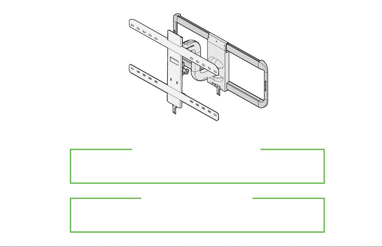
Sanus VLF515 User manual

THANK YOU FOR CHOOSING SANUS
THE #1 TV MOUNT BRAND IN THE US.
Scan for easy
install video
VLF
515
Instruction Manual

WARNING:This product contains a magnet. If an implanted medical device such as a pacemaker or implantable cardioverter defibrillator (ICD) is in use, magnetic fields may aect the operation of
those devices, resulting in serious injury or death. If you have an implanted medical device, keep at least 13 cm (5in.) between your device and the magnet. Please consult with your physician or medical
professional prior to using this product.
SANUS
MAGNETIC STUD FINDER
Designed to find your studs and make life easier– included in hardware kit.
TWO SIMPLE STEPS
TO FINDING YOUR STUDS:
Holding it vertically, lightly move the SANUS
Magnetic Stud Finder up and down while
sliding across your wall. The magnet within
will be attracted to the screws in the stud.
Once the magnet has landed on a screw,
place a pencil mark on the wall
directly below the magnet.
You can verify this is a stud by moving the
Magnetic Stud Finder up or down to find
a second or third screw within the wall.
Pull apart the SANUS Magnetic Stud Finder to
expose the probing pin within. Starting about
1/2inch away from the first pencil mark insert
the probing pin into the wall every 1/8inch until
it inserts completely into the wall. Once that
happens, you know you've found one edge of
your stud. Repeat this process till you have
found the stud edges and center of the stud.
Step 1 Step 2
magnet
locates screws in drywall
to show exactly where
your studs are
probing pin
helps find the edges of
your stud within the wall
level
attaches to your wall plate
for hands free leveling

3
Lo haremos sin estrés
Si tiene preguntas mientras realiza la instalación, llámenos.
1-800-359-5520 (Reino Unido: 0800-056-2853) Estamos listos para ayudarlo.
We’ll Make It Stress-Free
If you have any questions along the way, just give us a call.
1-800-359-5520 (UK: 0800-056-2853) We’re ready to help!
VLF515

4
IMPORTANT SAFETY INSTRUCTIONS – SAVE THESE INSTRUCTIONS – PLEASE READ ENTIRE MANUAL PRIOR TO USE
No
—
Perfect!
Yes
—
This mount is NOT compatible. Visit MountFinder.Sanus.com or call
1-800-359-5520 (UK: 0800-056-2853) to find a compatible mount.
Please read through these instructions completely to be sure you’re comfortable with this easy install process.
Also check your TV owner’s manual to see if there are any special requirements for mounting your TV.
If you do not understand these instructions or have doubts about the safety of the installation, assembly or use
of this product, contact Customer Service at 1-800-359-5520 (UK: 0800-056-2853).
Do you have
all the tools
needed?
Before getting started, let’s make sure this mount is perfect for you!
1
2
3
4
What is your
wall made of? Unsure?
Drywall with
wood studs?
Solid concrete or
concrete block?
125 lbs.
(56.7 kg)
CAUTION: Avoid potential personal injuries and property damage!
●This product is designed for use in wood stud, solid concrete, and concrete block walls - DO NOT install into drywall alone
●The wall must be capable of supporting five times the weight of the TV and mount combined
●Do not use this product for any purpose not explicitly specified by manufacturer
●Manufacturer is not responsible for damage or injury caused by incorrect assembly or use
Call Customer Service:
1-800-359-5520 (UK: 0800-056-2853)
Perfect! Perfect!
Ready to
begin?
Does your TV weigh
more than 125 lbs.
(56.7 kg) including
accessories?
Para Español ver página 32
Wood Stud Install
Concrete Install
Pencil Screwdriver
Tape
Measure
7/32 in.
(5.5 mm)
Wood
Drill Bit
Electric Drill Hammer
1/2 in.
(13 mm)
Socket
Wrench Drill Bit
3/8 in.
(10 mm)
Concrete
CAUTION:
DO NOT install
into drywall alone

5
STEP 1 Attach Bracket to TV
Vertical
TV Bracket
04 x1
NOTE: Not all hardware included will be used.
WARNING: This product contains small items that could be a choking hazard if swallowed.
Before starting assembly, verify all parts are included and undamaged. If any parts are missing or damaged, do not return the damaged
item to your dealer; contact Customer Service. Never use damaged parts!
Parts and Hardware for STEP 1
M4x35 mm
M5x35 mm
M6x35 mm
M8x35 mm
06
08
09
x4
x4
x4
05
07
10 11
x4
13
x4
x4
x4
x4
TV Screws TV Washers
Spacers
Thumb Screws
M8x45 mm
S
12
x4
03
x1
Upper
TV Bracket
TV Bracket
Plate
Lower
TV Bracket
01 x1
02 x1

6
1.1 Select TV Screws
Hand thread screws into the threaded inserts on the back of your TV
to determine which screw diameter (M4, M5, M6, or M8) to use.
1.2 Spacers
M4 M6 M8M5
Mount the spacers 12
above the TV bracket,
so the TV bracket sits
close to the TV surface
for flat back panels.
Mount the spacers 12
under the TV bracket to
create extra space needed
for irregular shape TV
backs or large cables.
Round Back CablesInset HolesFlat Back
TV Bracket
TV Bracket
12
12
ab
Spacers and screws are supplied to install your TV bracket.
Determine your preference for spacer configuration when
attaching your TV bracket.
CAUTION: Verify adequate thread engagement of the screw/
spacer combination on your TV.
Too short will not hold the TV and too long will damage the TV.
Too Short Correct Too Long

7
1.3 Attach TV Brackets
1. Slide TV bracket plate 03 into upper TV bracket 01 and loosely install using two thumb screws 13 .
2. Slide the upper 01 and lower 02 TV brackets onto the ends of the vertical TV bracket 04 .
01
04
02
0301
13
04
01
03
1 2

8
bSpacer, screw and washer
aSpacer, screw and washer
12
12
3. Position the TV bracket assembly over your TV hole pattern, center horizontally and
loosely install using the spacer, TV screw and washer combination (a) or (b) you
selected for your TV.
CAUTION: Avoid potential personal injury or property damage! The TV
Bracket assembly MUST BE installed with the release cord Roriented on the
bottom of the TV as shown.
01
04
02
3
If your TV included inset spacers or
wall mount adapters,
see Troubleshooting
on PAGES 27-28.
10
10
11
11
05
05
06
06
07
07
08
08
09
09
R

9
01
4. Vertically center TV bracket 04 .
5. Visually line up the locator hole Bin the lower TV bracket 02 , with a hole in the vertical TV bracket 04 and install using
two thumb screws 13 . Tighten the four thumb screws 13 on the upper 01 and lower 02 TV brackets.
5
413
B
01
02
04
02 04 13

10
6. Tighten the four TV screws (PAGE 8) on the upper 01 and lower 02 TV brackets.
6
TV Screws
02
01

11
5⁄16 in. x 2 3⁄4 in.
UX10 x 60R
Parts and Hardware for STEP 2
14 x1
Wall Plate
Template
STEP 2 Attach Wall Plate to Wall
Lag Bolt
Concrete Anchors
For concrete installations ONLY
17 x4
15 x1
16 x1
18 x4
WARNING: This product contains small items that could be a choking hazard if swallowed. Before starting assembly, verify all parts are included and
undamaged. If any parts are missing or damaged, do not return the damaged item to your dealer; contact Customer Service. Never use damaged parts!
Wall Plate
*WARNING:This product contains a magnet. If an implanted medical device such as a pacemaker or implantable cardioverter defibrillator
(ICD) is in use, magnetic fields may aect the operation of those devices, resulting in serious injury or death. If you have an implanted medical device,
keep at least 13 cm (5 in.) between your device and the magnet. Please consult with your physician or medical professional prior to using this product.
NOTE: Not all hardware included will be used. Sanus Magnetic Stud Finder *
CAUTION: Do not use in drywall or wood

12
CAUTION: Avoid potential
personal injuries and property damage!
●Drywall covering the wall must not
exceed 5/8 in. (16 mm)
●Minimum wood stud size:
common 2 x 4 in. (51 x 102 mm)
nominal 1½ x 3½ in. (38 x 89 mm)
●Minimum horizontal space between
fasteners: 16 in. (406 mm)
●Stud centers must be verified – not all
walls have conventional 16 in. (406 mm)
or 24 in. (610 mm) stud spacing
1. Locate a nail/screw in the studs
using the Sanus magnetic stud
finder 16 provided.
2. Find the edges of the studs using the
probe of the stud finder 16 .
3. Mark the centers of the studs with
a pencil.
1 2 3
16
16
Max. 5/8 in. (16 mm)
Min. 16 in. (406 mm) Min. 3 1/2 in. (89 mm)
Min. 1 1/2 in. (38 mm)
STEP 2A Wood Stud Option

13
4. Place the wall plate template 14 at your desired height and position the slotted holes over your stud center lines. Level the wall plate
template 14 and tape in place.
NOTE: For assistance in determining wall plate location, see HeightFinder at sanus.com.
IMPORTANT: Be sure you mark and drill into the center of the stud.
5. Drill the four pilot holes using a 7/32 in. (5.5 mm) diameter drill bit.
IMPORTANT: Pilot holes must be drilled to a depth of 3 in. (75 mm).
1414
16
4 5
3 in. (75 mm)
7/32 in.
(5.5 mm)

14
6. Remove the wall plate template 14 .
7. Slide the covers Copen on the wall plate 15 to expose the mounting holes.
14
615 C
C
7

15
8. Install the four lag bolts 17 . Firmly tighten all four lag bolts 17 until they are pulled flush against the wall plate 15 .
NOTE: Hold the wall plate 15 in place when tightening the first lag bolt 17 to keep the plate from shifting out of place.
CAUTION: Avoid potential personal injury or property damage! All four lag bolts 17 MUST BE firmly tightened to prevent unwanted
movement of the wall plate 15 .Ensure the wall plate is securely fastened to the wall before continuing on to the next step.
9. Slide the covers Cclosed on wall plate 15 .
Go to STEP 3 on PAGE 19.
15
C
C
9
15
817

16
CAUTION: Avoid potential personal injuries and property damage!
●Mount the wall plate 15 directly onto the concrete surface
●Minimum solid concrete thickness: 8 in. (203 mm)
●Minimum concrete block size: 8 x 8x 16 in. (203 x 203 x 406 mm)
●Minimum horizontal space between fasteners: 24 in. (610 mm)
●For concrete applications, arm 19 (STEP 3) must remain centered in wall plate 15 . Keep this in mind when selecting the wall plate location.
1. Position the wall plate template 14 on the wall at your desired height. Level the wall plate template and mark the hole locations.
NOTE: For assistance in determining wall plate location, see Height Finder at sanus.com.
2. Drill four pilot holes using a 3/8 in. (10 mm) diameter drill bit.
IMPORTANT: Pilot holes must be drilled to a depth of 3 in. (75 mm). Never drill into the mortar between blocks.
1414
16
1 2
3/8 in.
(10 mm)
3 in. (75 mm)
Min.
24 in.
(610 mm)
STEP 2B Solid Concrete or Concrete Block Option

17
3. Remove the wall plate template 14 and insert four anchors 18 .
CAUTION: Be sure the anchors 18 are seated flush with the concrete surface.
4. Slide the covers Copen on the wall plate 15 to expose the mounting holes.
14
3
15
C
C
4
18

18
5. Install the four lag bolts 17 . Firmly tighten all four lag bolts 17 until they are pulled flush against the wall plate 15 .
NOTE: Hold the wall plate 15 in place when tightening the first lag bolt 17 to keep the plate from shifting out of place.
CAUTION: Avoid potential personal injury or property damage! All four lag bolts 17 MUST BE firmly tightened to prevent unwanted
movement of the wall plate 15 .Ensure the wall plate is securely fastened to the wall before continuing on to the next step.
6. Slide the covers Cclosed on wall plate 15 .
15
C
C
6
15
517

19
Part for STEP 3
STEP 3 Attach TV to Wall Plate
Arm Assembly
WARNING: Before starting assembly,
verify this part is undamaged. If damaged, do not
return the damaged item to your dealer; contact
Customer Service. Never use damaged parts!
19 x1

20
3.1 Attach Arm Assembly to Wall Plate
1
CAUTION: Avoid potential personal injury or property damage! The arm assembly 19 MUST BE installed with the lock lever Loriented
on the bottom as shown.
1. Slide the lock lever Lto the unlock position.
Unlock
Lock
L
L
19
Table of contents
Other Sanus TV Mount manuals

Sanus
Sanus Simplicity SMF3 User manual

Sanus
Sanus DMF215 User manual

Sanus
Sanus FPA400 User manual

Sanus
Sanus VLL5-B1 User manual

Sanus
Sanus VisionMount VLT15 User manual

Sanus
Sanus New VisionMount VMT15 User manual

Sanus
Sanus VLC1 User manual

Sanus
Sanus LLF122 User manual

Sanus
Sanus ATVS1 User manual

Sanus
Sanus VisionMount LT25 User manual

Sanus
Sanus BLL2 User manual

Sanus
Sanus DMF115 User manual

Sanus
Sanus BML1 User manual

Sanus
Sanus VXF730-B2 User manual

Sanus
Sanus HLF112 User manual

Sanus
Sanus SAN12 User manual

Sanus
Sanus VisionMount VMDD26 User manual

Sanus
Sanus VLF525-B3 User manual

Sanus
Sanus BXL1 User manual

Sanus
Sanus Visionmount FFSF1A User manual