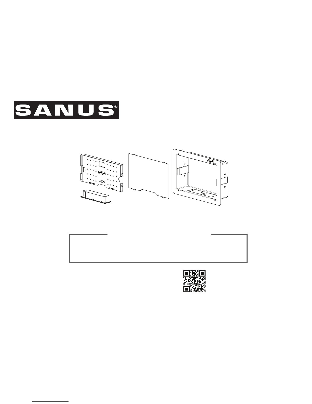
Sanus SA809 User manual

SA809 INSTRUCTION MANUAL
We’ll Make It Stress-Free
If you have any questions along the way, just give us a call.
1-800-359-5520. We’re ready to help!
Scan for more information
san.us/448

2
IMPORTANT SAFETY INSTRUCTIONS – SAVE THESE INSTRUCTIONS – PLEASE READ ENTIRE MANUAL PRIOR TO USE
Do you have all of the tools needed?
Before getting started, let’s make sure this product is perfect for you!
1
2
3
4
What is your wall made of?
Unsure? Call 1-800-359-5520 [UK: 0800 056 2853]
Perfect!
Drywall with
wood studs ?
Will your accessories weigh more than 30 lb (13.6 kg)?
No
—
Perfect!
Yes
—
This product is NOT compatible. Visit Sanus.com or call 1-800-359-5520 [UK: 0800 056 2853] to find a compatible product.
30 lb
(13.6 kg)
Ready to begin?
Please read through these instructions completely to be sure you’re comfortable with this easy install process.
If you do not understand these instructions or have doubts about the safety of the installation, assembly or use of this product, contact
Customer Service at 1-800-359-5520 [UK: 0800 056 2853].
CAUTION: Avoid potential personal injuries and property damage!
ƕDo not use this product outdoors
ƕThis in-wall system is for use with ITE or Audio/Video equipment only
ƕThe maximum specified ambient temperature of the cabinet system is 40o - 120oF (4o - 49oC)
ƕDo not use this product for any purpose not explicitly specified by manufacturer
ƕManufacturer is not responsible for damage or injury caused by incorrect assembly or use

3
WARNING! This product contains small items that could be a choking hazard if swallowed.
Before starting assembly, verify all parts are included and undamaged. If any parts are missing or damaged, do not return the damaged item
to your dealer; contact Customer Service. Never use damaged parts!
Supplied Parts
STEP 1 Parts STEP 2 Parts STEP 3 Parts
04
05 (2)
06
ECO-Mini Bracket
Component Panel
Elastic-Velcro Strap
Cover
01
Template
02
03
Housing

4
1 2
≤ 16 mm
(5/8 in.)
STEP 1 Cut Hole for Housing
01
CAUTION: Avoid potential personal injuries and property damage!
ƕDrywall covering the wall must not exceed 16 mm (5/8 in.).
ƕBox must be mounted between studs that are at least 406 mm (16 in.) apart. After installation there will not be enough space between the
SA809 and the studs for electrical wires/cables, plumbing, ductwork, or insulation. Choose your SA809 location carefully.
1. Locate the studs using an edge-to- edge stud finder. Verify the edges of the studs using an awl or thin nail. Mark the edges of the studs
with pencil.
2. Center the template 01 between the two studs. Level the template 01 and use a pencil to mark the open area of the template 01 .

5
STEP 1 Cut Hole for Housing cont.
3 4
3. Use a drywall saw or similar tool to cut the drywall where marked. Remove cut section of drywall.
WARNING! ELECTRICAL SHOCK HAZARD! CUTTING OR DRILLING INTO ELECTRICAL WIRES OR CABLES CAN CAUSE DEATH OR
SERIOUS PERSONAL INJURY! Always make certain the area behind mounting surfaces is free of electrical wires and cables before cutting,
drilling, or installing fasteners.
WARNING! EXPLOSION AND FIRE HAZARD! CUTTING OR DRILLING INTO GAS PLUMBING CAN CAUSE DEATH OR SERIOUS
PERSONAL INJURY! Always make certain the area behind mounting surfaces is free of gas, water, waste, or any other plumbing before
cutting, drilling, or installing fasteners.
4. Install wires and cables.

6
1 2
02 02
STEP 2 Install Housing
1. Break out the sections of the housing 02 . Optionally, install a UL Listed 120 VAC electrical outlet box (not included) capable of attaching
to the SA809 housing 02 following the instructions included with the outlet box.
NOTE: Knockouts are provided for ease of installation. Any unused knockouts that have been punched are to be closed up with a metal
plug.
2. Carefully fit the housing 02 into the cutout section of the wall.

7
3
View Behind the Wall
STEP 2 Install Housing cont.
02
02
3. Using a screwdriver, turn the screws in the corners of the housing 02 . These will raise the locking tabs in the rear of the housing 02 to
secure it to the wall. Tighten only until secure. Do not over-tighten screws.

8
STEP 3 Install Components
1
ECO-Mini (purchased separately) with the SA809 - Optional
NOTE: Minimum spacings between the accessories and components and the housing for Information Technology Communication Equipment
shall be maintained for safe operation of the equipment when installed in accordance with the National Electric Code, ANSI/NFPA 70-1999.
Refer to communication equipment manufacturer’s specifications for minimum spacings.
1. To use the ECO-Mini (purchased separately) in the SA809, first remove feet.
2. Fit the ECO-Mini into the ECO-Mini bracket 03 supplied with the SA809.
2
03

9
4
STEP 3 Install Components cont.
03
02
ECO-Mini (purchased separately) with the SA809 - Optional
3
3. Use two of the screws from the feet to secure the ECO-Mini in the bracket 03 .
4. Slide the ECO-Mini and bracket 03 into the top of the housing 02 . Lock the bracket 03 into the housing 02 by sliding it towards the
corner until you feel it catch.
03

10
STEP 3 Install Components cont.
5
04
04
5. Use elastic-velcro straps 05 to attach components to the front of the component panel 04 and to secure wires to the back of the panel.
NOTE: Zip ties can also be used by looping them through the holes of the component panel 04 to secure components to the
component panel
04 .
05
05
05
05

11
6
STEP 3 Install Components cont.
04
04
02
02
6. To mount the component panel 04 , press the component panel 04 into the housing 02 until the side buttons "snap" into the
depressions in the sides of the housing 02 .
To remove component panel 04 , grasp
panel in the center and pull straight out.

12
7
STEP 3 Install Components cont.
06
02 02
06
7. Install cover
06 by fitting the bottom tabs of the cover 06 into the bottom slots of the housing 02 . Press near the upper tabs of the
cover 06 to "snap" them into the upper slots of the housing 02 .

13
Positioning
The SA809 can be installed behind most large wall plates of wall mounts. To access the SA809 after installation, disconnect all cables and
wires from the TV, then either slide or remove the arm or TV mount from the wall plate.
IMPORTANT: Check your TV owner’s manual to see if there are any special requirements for mounting or removing your TV.

14
Dimensions
11.40 in.
[289.6 mm]
14.2 in.
[360.7 mm]
8.84 in.
[224.6 mm]
14.07 in.
[357.5 mm]
16.63 in.
[422.4 mm]
3.92 in.
[99.6 mm]
4.00 in.
[101.6 mm]
2.87 in.
[72.9 mm]
0.75 in.
[19.1 mm]

15

16
ESPAÑOL
INSTRUCCIONES DE SEGURIDAD IMPORTANTES. CONSÉRVELAS. LEA TODO EL MANUAL ANTES DE UTILIZAR ESTE PRODUCTO.
Antes de comenzar, verifiquemos que este producto sea el ideal para sus necesidades. Ver página 2
1. ¿Los accesorios pesan más de 13,6 kg (30 lb)?
No
—
¡Perfecto!
Sí
—
Este producto NO es compatible. Visite Sanus.com o llame al 1-800-359-5520 (Reino Unido: 0800-0562853) para encontrar un
producto compatible.
2. ¿De qué está hecha su pared?
3. ¿Tiene todas las herramientas necesarias?
4. ¿Listo para comenzar?
Lea estas instrucciones en su totalidad para estar seguro de sentirse cómodo con este fácil proceso de instalación.
Si no entiende las instrucciones o si tiene dudas acerca de la seguridad de la instalación, del ensamblado o del uso del producto, póngase en
contacto
con el servicio de atención al cliente al 1-800-359-5520 (Reino Unido: 0800 056 2853].
PRECAUCIÓN: Evite lesiones y daños materiales.
ƕNo utilice este producto al aire libre
ƕEste sistema en la pared es para uso con ITE o Sólo audio equipos / Video
ƕLa temperatura ambiente máxima especificada del sistema de gabinete es 40o - 120 º F (4o - 49 º C)No utilice este producto para ningún
otro propósito que no sea el especificado explícitamente por el fabricante.
ƕEl fabricante no se responsabiliza por ningún daño o lesión resultante del montaje incorrecto o de uso indebido.
Piezas suministradas Ver página 3
ADVERTENCIA: Este producto contiene piezas pequeñas que, si fuesen tragadas, podrían producir asfixia.
Antes de iniciar el ensamblaje, compruebe que todas las piezas estén incluidas y en buenas condiciones. Si faltan piezas o alguna está
dañada, no devuelva el artículo al distribuidor; póngase en contacto con el servicio de atención al cliente. Nunca utilice piezas deterioradas.
PASO 1: Haga espacio para la carcasa Ver página 4
PRECAUCIÓN: Evite lesiones y daños materiales.
ƕEspesor mínimo de yeso: 1/2" (13 mm).
ƕLa caja debe colocarse entre montantes que tengan una distancia de separación mínima de 16" (406 mm).

17
1. Localice los montantes con un detector de bordes de montantes. Busque los bordes de los montantes con un punzón o clavo.
Marque los bordes de los montantes con un lápiz.
2. Centre la plantilla 01 entre los dos montantes. Nivele la plantilla 01 y use un lápiz para marcar el área abierta de la plantilla 01 .
3. Use una sierra para yeso o una herramienta similar para cortar el yeso donde hizo las marcas. Retire la sección de yeso que cortó.
¡ADVERTENCIA! ¡Riesgo de descarga eléctrica! Evite el riesgo de lesiones graves o muerte. Asegúrese de que no haya cables
de electricidad en la pared antes de cortar o taladrar la superficie.
¡ADVERTENCIA! ¡Riesgo de explosiones e incendios! Evite el riesgo de lesiones graves o la muerte. Asegúrese de que no haya
tuberías de gas en la pared antes de cortar o taladrar la superficie.
4. Coloque los cables.
PASO 2: Colocar la carcasa Ver página 6
1. Romper con los sectores de la vivienda. Opcionalmente, instale una lista de UL 120 VAC caja eléctrica de salida (no incluido) capaz de
unirse a la carcasa 02 SA809 siguiendo las instrucciones incluidas en la caja de salida.
2. Con cuidado, coloque la carcasa 02 en la sección que cortó de la pared.
3. Con un destornillador, ajuste los tornillos de las esquinas de la carcasa 02 . Esto hará que las lengüetas de bloqueo se levanten en la
parte posterior de la carcasa 02 y la fijen a la pared. Ajuste solo hasta que quede fija. No ajuste en exceso los tornillos.
PASO 3: Colocar los componentes Ver página 8
ECO-Mini (se vende por separado) con SA809 - Opcional
NOTA: Distancias mínimas entre los accesorios y componentes y la carcasa de Tecnología de la Información Equipo de
Comunicación se mantendrán para el funcionamiento correcto de este equipo cuando se instala de acuerdo con el Código
Eléctrico Nacional, ANSI / NFPA 70-1999. Consulte las especificaciones del equipo de comunicación del fabricante para
distancias mínimas.
ESPAÑOL

18
ESPAÑOL
1. Para usar ECO-Mini (se vende por separado) en SA809, primero retire la base.
2. Coloque ECO-Mini en la placa de sujeción del ECO-Mini 03 incluida con SA809.
3. Use dos de los tornillos de la base para asegurar el ECO-Mini en la placa de sujeción 03 .
4. Deslice el ECO-Mini y la placa de sujeción 03 en la parte superior de la carcasa 02 . Bloquee la placa de sujeción 03 en la carcasa.
5. Para ello,
02 deslícela hacia la esquina hasta que se enganche. Use las tiras elásticas de velcro 05 para sostener los componentes a
la parte frontal del panel de componentes 04 y para sujetar los cables a la parte posterior del panel.
NOTA: También se pueden usar cinchos. Para ello, páselos a través de los orificios del panel de componentes 04 y átelos para
sujetar los componentes del panel 04 .
6. Para instalar el panel de componentes 04 , presiónelo 04 en la carcasa 02 hasta que los botones laterales "encajen" en los huecos de
la carcasa 02 .
7. Coloque la cubierta 06 . Para ello, introduzca las lengüetas inferiores de la cubierta 06 en las ranuras inferiores de la carcasa 02 .
Presione cerca de las lengüetas superiores de la cubierta 06 para que "encajen" en las ranuras superiores de la carcasa 02 .
Posicionamiento Ver página 13
SA809 se puede colocar detrás de la mayoría de las placas murales de los soportes murales. Para tener acceso a SA809 después de la
instalación, desconecte todos los cables del televisor, luego deslice o retire el brazo o el soporte del televisor de la placa mural.
IMPORTANTE: Consulte el manual del usuario de su televisor para ver si existe algún requisito especial para instalar o retirar su
televisor en la pared.
Dimensiones Ver página 14

19
ESPAÑOL

20
6901-002316 01
Milestone AV Technologies and its aliated corporations and subsidiaries (collectively, “Milestone”), intend to make this manual accurate and complete. However,
Milestone makes no claim that the information contained herein covers all details, conditions, or variations. Nor does it provide for every possible contingency in
connection with the installation or use of this product. The information contained in this document is subject to change without notice or obligation of any kind.
Milestone makes no representation of warranty, expressed or implied, regarding the information contained herein. Milestone assumes no responsibility for accuracy,
completeness or suciency of the information contained in this document.
©2013 Milestone AV Technologies. All rights reserved. Sanus is a division of Milestone.
All other brand names or marks are used for identification purposes and are trademarks of their respective owners.
Thank you for choosing Sanus! Please take a moment to let us know how we did:
SANUS&LW\:HVW3DUNZD\(GHQ3UDLULH0186$
Call us: 1-800-359-5520
UK: 0800 056 2853
Find us on Facebook: SANUS Follow us on Twitter @sanussystems
Table of contents
Other Sanus TV Mount manuals

Sanus
Sanus VisionMount LT25 User manual

Sanus
Sanus VisionMount VLF210 User manual

Sanus
Sanus Vuepoint F35c User manual

Sanus
Sanus VML5 User manual

Sanus
Sanus 65PFL5604/F7 User manual

Sanus
Sanus VLC1 User manual

Sanus
Sanus VLF515 User manual

Sanus
Sanus VLF320 User manual

Sanus
Sanus DMF115 User manual

Sanus
Sanus VisionMount LF228 User manual

Sanus
Sanus OLT15 User manual

Sanus
Sanus ATVS1 User manual

Sanus
Sanus MLF13 User manual

Sanus
Sanus BLL1 User manual

Sanus
Sanus BML1 User manual

Sanus
Sanus New VisionMount VST15-B1 User manual

Sanus
Sanus Classic MLL10 User manual

Sanus
Sanus CLASSIC MLT14 User manual

Sanus
Sanus NEW VisionMount VLT14 User manual

Sanus
Sanus LLF122 User manual