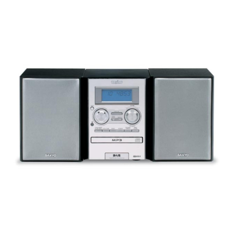
Sanyo RB-DA280 User manual

4
ESPAÑOL
ENGLISH
INSTRUCTION MANUAL DC-DA280
Micro Component System
MEMORY
REPEAT
FM MODE
SOUND
PRESET
PRESET
TUNER
/BAND TUNING
VOLUME
REMOTE CONTROLLER RB-DA280
LINE

1
CAUTION – USE OF CONTROLS OR ADJUSTMENTS OR PERFORMANCE OF PROCEDURES OTHER THAN THOSE
SPECIFIED IN THE OPERATING INSTRUCTIONS MAY RESULT IN HAZARDOUS RADIATION EXPOSURE.
THIS PRODUCT SHOULD NOT BE ADJUSTED OR REPAIRED BY ANYONE EXCEPT PROPERLY QUALIFIED
PERSONNEL.
PRECAUCION – EL USO DE LOS CONTROLES O AJUSTES, O EL RENDIMIENTO DE PROCEDIMIENTOS NO
ESPECIFICADOS EN LAS INSTRUCCIONES DE OPERACION PUEDEN RESULTAR EN EXPOSICION A RADIACION
DAÑINA.
ESTE PRODUCTO SOLO DEBE SER REPARADO O AJUSTADO POR PERSONAL DEBIDAMENTE CALIFICADO.
CAUTION – INVISIBLE LASER RADIATION WHEN OPEN AND
INTERLOCKS DEFEATED. AVOID EXPOSURE TO BEAM.
ADVARSEL – USYNLIG LASER STRÅLING VED ÅBNING, NÅR
SIKKERHEDSAFBRYDERE ER UDE AF FUNKTION, UNDGÅ UDS ÆTTELSE
FOR STRÅLING.
VARNING – OSYNLIG LASER STRÅLNING NÄR DENNA DEL ÄR ÖPPNAD
OCH SPÄRR ÄR URKOPPLAD. STRÅLEN ÄR FARLIG.
VORSICHT – UNSICHTBARE LASERSTRAHLUNG TRITT AUS, WENN
DECKEL GEÖFFNET UND WENN SICHERHEITSVERRIEGELUNG
ÜBERBRÜCKT IST. NICHT, DEM STRAHL AUSSETZEN.
VARO – AVATTAESSA JA SUOJALUKITUS OHITETTAESSA OLET ALTTIINA
NÄKYMÄTTÖMÄLLE LASERSÄTEILYLLE. ÄLÄ KATSO SÄTEESEEN.
CLASS 1 LASER PRODUCT
LUOKAN 1 LASERLAITE
KLASS 1 LASERAPPARAT

2
Screws (not supplied)
12
1
2
3
External aerial
Aerial wire
AM loop aerial
Video/ Auxiliary equipment
L ch speaker
R ch speaker
To an AC outlet
Two R03 batteries
(not supplied)
1
2
Within approx.
7 meters
Remote sensor
MEMORY
REPEAT
FM MODE
SOUND
PRESET
PRESET
TUNER
/BAND TUNING
VOLUME
REMOTE CONTROLLER RB-DA280
LINE
Fig. 1
Fig. 3b
Fig. 3a
Fig. 4
Fig. 2

3
Fig. 5a Fig. 5b
Fig. 5c Fig. 5d
Fig. 6
Fig. 7 Fig. 8
Fig. 10
Fig. 9
Fig. 11
Break out tab A for side A.
Break out tab B for side B.
Side A
Side B
1. Cotton swab
2. Capstan
3. Pinch roller
4, 5. Head
7
6
5
4
12 3
9
8
123
8
75
4
6
12
5
4
3
11
10
9
86
7
5
4
3
2
1
MEMORY
REPEAT
FM MODE
SOUND
PRESET
PRESET
TUNER
/BAND TUNING
VOLUME
REMOTE CONTROLLER RB-DA280
LINE
5
1
2
43

4
Number buttons (1-9, 0)
These buttons are used to select the track numbers on a disc or preset
radio stations.
If the function is “CD”, the buttons select the track numbers on a disc.
If the function is “TUNER”, the buttons select preset radio stations.
With any other function, the buttons will not function.
- Two buttons must always be pressed.
Example:
To select No. 3, press 0, then 3.
To select No. 10, press 1, then 0.
To select No. 25, press 2, then 5.
REMOTE CONTROLS
Controls (Fig. 5d)
1. Number buttons (1-9, 0)
2. Cassette deck controls
r: Record muting button
m: Record/Record pause button
d, c: Fast forward/Rewind buttons
a: play button
n: Stop button
3. FM mode button (FM MODE)
4. CD player controls
i: Play/Pause button
n: Stop button
REPEAT: Repeat button
5. Memory button (MEMORY)
6. Sound preset button (SOUND PRESET)
7. Tuning buttons (TUNING +, -, f, e)
(These buttons can also be used as CD playing tracks skip and
search button)
8. Tuner function/Band select button (TUNER/BAND)
9. Volume buttons (VOLUME +, -)
10. Preset tuning button (PRESET)
11. Line function button (LINE)
CONNECTIONS (Fig. 1)
Note:
- Do not connect the mains lead to an AC outlet until all connections
have been made.
- The system is not completely disconnected from the mains when the
power button is set to the Y OFF position.
Speakers
Connect the connector of the left speaker lead to the “L” SPEAKERS
socket and the connector of the right speaker lead to the “R” socket.
If you have difficulty inserting the speaker lead connector, turn it over and
reinsert it.
FM aerial
Extend the aerial wire as straight as possible and, while listening to the
sound from the system, secure it in a position which yields minimal
distortion and noise.
Note:
To minimize noise, the speaker, mains and any other leads should not
come close to the indoor or external aerial lead and AM loop aerial. Do
not place the aerial leads close to the system.
Video/Auxiliary equipment
Connect audio leads (not supplied) from the audio output sockets of a
video/auxiliary equipment to the LINE IN sockets.
Headphones
Connect stereo headphones (not supplied) to the PHONES socket for
monitoring or for private listening. The speakers are automatically
disconnected when headphones are connected.
AM Loop aerial
Assemble the loop aerial as shown in Fig. 3a. Unwind the aerial wires,
then connect them to the AM LOOP terminals. Place the loop aerial in a
position which yields the best AM reception, or attach it to a wall or other
surface as shown in Fig. 3b.
CONTROLS (Fig. 5)
General (Fig. 5a)
1. Power button (YOFF, Z ON)
2. Display
3. Remote sensor (IR)
4. Function button (FUNCTION)
5. Bass expander button (BASS)
6. Sound preset button (SOUND PRESET)
7. Surround button (SURROUND)
8. Headphones socket (PHONES)
9. Volume control (VOLUME)
CD player/ Tuner (Fig. 5b)
1. Repeat play button (REPEAT)
2. Play/Pause button (CD)
3. CD Compartment lid
4. Stop/Clear button (N)
5. Tuner function/Band select button (TUNER/BAND)
6. Tuning buttons (TUNING -, +)
7. Skip/Search/Preset tuning buttons
(PRESET -, +/ F, E)
8. FM mode button (FM MODE)
Cassette deck (Fig. 5c)
1. Play button (TAPE)
2. Stop button (N)
3. Cassette holder
4. Fast forward/ Rewind buttons
(PRESET -, +/ F, E)
5. Record/ Record pause button (j)
PRECAUTIONS
- The apparatus shall not be exposed to dripping or splashing.
- Do not use where there are extremes of temperature (below 5°C or
exceeding 35°C) or where direct sunlight may strike it.
- Because of the CD player’s extremely low noise and wide dynamic
range, there might be a tendency to set the volume on the amplifier
unnecessarily high. Doing so may produce an excessively large
output from the amplifier which could damage your speakers.
- Sudden changes in the ambient temperature may cause condensa-
tion to form on the optical lens inside the unit. If this happens, take
out the disc, leave the unit for about 1 hour, and then proceed to
operate.
- The system’s speakers use powerful magnets. Do not place
timepieces, credit cards, cassette tapes or video tapes, etc. near the
speakers.
- Do not install this equipment in a confined space, such as a book
case or built in cabinet.
ENGLISH

5
GENERAL OPERATION
Turning the power on and off
To turn the power on, press the power button and the display lights.
To turn the power off, press the power button again, the display goes out.
Selecting the function
Press the FUNCTION button to select the desired function as follows
display shows.
Cd vTAPE vTU vLInE vCd v...
The function is automatically selected when CD play or type playback is
started or when the TUNER/BAND button has been pressed (except
during recording).
- When the function selection is changed, CD play or tape playback is
automatically stopped.
Adjusting the volume
Turn the VOLUME control, (or press the + or - VOLUME button on the
remote control). The volume level appears on the display. (VOL 0 ~ VOL
40)
Surround sound button
Press the SURROUND button, “SURR” appears on the display and a 3
dimensional sound effect is created.
Bass expander button
Press the BASS button to enhance the bass sound.
“BASS” appears on the display.
Selecting the sound mode
Press the SOUND PRESET button to select the sound mode matching
the music to be listened to.
POP: Pops, etc.
ROCK: Rock music, etc.
JAZZ: Jazz, etc.
CLASSIC: Classical music, etc.
WHAT TO DO IF ...
If the operation of the unit or display is not normal,
1. Disconnect the mains lead.
2. Press the CD button on the unit for at least 30 seconds.
3. Connect the mains lead.
4. Operate the unit.
Search (forward/reverse)
If the For Ebutton is pressed during play, the player will search at
high speed in the forward or reverse direction while the button is being
pressed. When the button is released, normal play will continue.
Repeat play
Press the REPEAT button before or during play. The player will play all
the tracks or all the programmed tracks repeatedly. “ ” appears. To
cancel repeat play, press the REPEAT button again. “ ”disappears.
CD PLAY
Use compact discs bearing the symbol shown in Fig. 6. In addition to
conventional 12 cm CDs, this system can be used to play 8 cm CDs
without an adapter.
1. Press the FUNCTION button to select “CD” function.
2. Press the CD compartment lid (q CD OPEN/CLOSE portion). The
CD compartment opens.
3. Place the disc with the label facing up on the disc turntable (Fig. 6).
(Place only one disc at a time.)
4. Press the CD compartment lid (qCD OPEN/ CLOSE portion) to
close it.
The total number of tracks and total playing time on the disc appear.
Note:
If the disc is loaded with the label facing downward, or if a badly
scratched disc is loaded, “Cd” appears. If this occurs, load the disc
correctly or replace the damaged disc.
5. Press the CD button. Play starts from the first track.
The current track number and elapsed playing time are displayed.
6. Press the Nbutton to end disc play.
When the last track has been played, the player stops automatically.
Note:
Always press the Nbutton and wait for the disc to stop rotating before
opening the CD compartment.
Notes on handling compact discs
- Do not expose the disc to direct sunlight, high humidity or high
temperatures for extended periods of time.
- Discs should be returned to their cases after use.
- Do not apply paper or write anything on the disc surface.
- Handle the disc by its edge. Do not touch the playing surface (glossy
side).
- Fingerprints and dust should be carefully wiped off the playing
surface of the disc with a soft cloth.
Wipe in a straight motion from the centre to the outside of the disc.
- Never use chemicals such as record cleaning sprays, antistatic
sprays or fluids, benzene or thinner to clean compact discs.
To start play from the desired track
Select the track by using the For Ebutton, then press the Ak
button.
Using the remote control
Press two number buttons within 2 seconds. (Example: press 0, then 3.)
Temporarily stopping play
Press the CD button. “ a” blinks on the display. To resume play, press
the button again.
Skip play
To skip to track 6 while track 3 is playing, press the Ebutton repeatedly
until “6” appears (in the track section) on the display. To skip back to track
3 while track 6 is playing, press the Fbutton repeatedly until “3”
appears.
- The number buttons on the remote control can also be used for skip
play. To skip to track 6 while one track is playing, press 0, then 6.
Inserting batteries (Fig. 2)
Note:
Always remove batteries if the remote control is not to be used for a
month or more. Batteries left in the unit may leak and cause damage.
Remote control range (Fig. 4)
The buttons on the remote control perform similar functions to similarly
marked buttons on the front panel.
PROGRAMMED PLAY
Up to 24 tracks on a disc can be programmed for play in any order.
- First, select “CD” function and load a disc that you want to programme.
- The tracks must be programmed in the stop mode.
- The same track can be programmed more than once.
1. Press the MEMORY button on the remote control.

6
2. Select a track by using the Eor F button.
- The number buttons on the remote control can also be used.
3. Press the MEMORY button.
4. Repeat steps 2-3 to programme additional tracks.
5. Press the Ak button to start programmed play.
When all programmed tracks have played. the player stops
automatically.
- The programme contents are retained in memory.
Any attempt to programme more than 20 tracks will result in “FULL”
being displayed and discontinuation of the programming.
The programme contents are retained even if the function selecton
is changed. After slecting “CD” function press the MEMORY button.
The programmed contents appear.
To cancel programmed play, press the Nbutton twice.
Checking the programme (Remote control only)
Each time the MEMORY button is pressed in the stop mode, the
programmed details sequentially appear on the display.
Changing a programme
To add a new track to a programme: (Remote control only)
1. In the stop mode, press the MEMORY button repeatedly until
“- -,- - - -” is displayed.
2. Select a track as explained above.
3. Press the MEMORY button.
To change a track: (Remote control only)
1. In the stop mode, press the MEMORY button repeatedly until the
track number to be replaced is displayed.
2. Select a track as explained above.
3. Press the MEMORY button.
Note:
Programmed details cannot be partially deleted or inserted.
LISTENING TO THE RADIO
Before use
When the unit is shipped from the factory, its AM freqency band is set as
“522-1611” kHz ( in 9 kHz steps)”.
If your local AM broadcast system is organized in 10 kHz steps, change
the frequency band to “520-1610 kHz (in 10 kHz steps)” as follows.
While pressing the Nbutton on the front panel, press the Ebut-
ton on the front panel.
To return the onginal setting repeat steps above.
Automatic/Manual tuning
1. Press the FUNCTION button to select TUNER. The radio frequency
appears.
2. Press the TUNER/BAND button to select FM, AM.
Automatic tuning
Press the TUNING - or TUNING + button for at least 1 second to tune
in a station. The unit will scan up or down the band and receive the
next receivable station. Press the button again to continue.
- The eor fbutton on the remote control can also be used.
Manual tuning
Press the TUNING - or TUNING + button briefly until the desired
frequency is displayed.
Note:
If the next step is not taken within 10 seconds while performing steps
2 - 4, “PROG.” disappears and the preset operation is cancelled.
Press the MEMORY button to continue.
5. Repeat steps above to add more preset stations.
- When presetting a new station, the previous preset station is
cleared.
Listening to preset stations
1. Press the TUNER/BAND button to select FM, AM.
2. Press the PRESET - or PRESET + button on the front panel (or
PRESET button on the remote control) to select the desired channel
number. The selected channel number appears briefly.
- The number buttons on the remote control can also be used.
Press two number buttons within 2 seconds.
To receive FM stereo broadcasts
“ST” appears when an FM stereo broadcast is received in the stereo
mode.
Make sure the reception mode is in stereo. orelse, press the FM MODE
button.
- If the signal from an FM stereo station is weak and reception is poor,
press the FM MODE button to change to the mono mode. The
reception may be improved, but the sound will be monaural.
When beat interference is heard (Remote control only)
A high-pitched noise called “beat” is sometimes heard during reception
of radio broadcasts. If this occurs.
1. Press the MEMORY button on the remote control.
2. When “PROG.” is blinking, press the FM MODE button to select “bc-
A” or “bc-b”. Select the setting that gives the best results.
To preset stations (Remote control only)
Up to 24 stations for FM band, 12 stations for AM band, can be preset.
1. Tune in the station to be preset as described above.
2. Press the MEMORY button on the remote control.
3. Press the PRESET - or PRESET + button on the front panel (or
PRESET button on the remote control) to select the channel number
to be preset.
4. While “PROG.” is blinking, press the MEMORY button. “PROG.”
disappears.
- In this example, “103.25 MHz” FM station is preset on FM channel
9.
- The number buttons on the remote control can also be used. In
this example, press 0, then 9 after the step 2 above.
LISTENING TO TAPES
1. Press the FUNCTION button to select “TAPE”.
2. Press the cassette holder (EJECT portion) to open it.
3. Load the cassette. (Fig. 7)
After loading the cassette, push the cassette holder back into
position.
4. Press the TAPE button to begin playback.
5. Press the Nbutton to stop playback at any time. Press it again to
remove the cassette.
When the end of the tape has been reached, automatic stop will be
activated.
7
Note:
- Use the normal tape (TYPE 1).
- Endless tapes cannot be used.
- Do not use C-100 (or longer) tapes. They may jam in the mechanism.
Fast forward and rewind
Press the For Ebutton. When the desired location has been
reached, press the Nbutton.
LISTENING TO OTHER SOURCES
1. Press the FUNCTION button to select “LINE”.
2. Follow the instructions supplied with the Video/Auxiliary equipment.
Recording copyright material without permission of the copyright
owners is usually an infringement. If you wish to re-record copyright
material, permission from the copyright owner is necessary. SANYO
does not approve of, and cannot be held responsible for, any unlawful
use of this machine.
Automatic record muting (Remote control only)
Undesirable parts of a programme can be omitted wile recording.
Press the rbutton once while recording. “REC” blinks and a 5-second
unrecorded blank space is created, then the deck enters the recording
pause mode. “REC” remains lit and “ a” blinks on the display.
- To add another 5-second blank space, press the rbutton again.
- To resume recording, press the TAPE button.
Safeguards against accidental erasure
Accidental erasure can be prevented by breaking out the tabs on the end
of the cassette tape (where the tape is not exposed) using a screwdriver
or similar implement.
If a tab is broken out in error and you wish to re-record the tape, simply
block the tab hole using adhesive tape and the tape can be used for
recording again.
Recording compact discs (Synchronous recording)
1. Select “CD” function.
2. Load the disc to be recorded.
- For programmed recording, programme the material in advance
(as described under “PROGRAMMED PLAY”).
3. Select the track number to be recorded if required.
- For programmed recording, this step is unnecessary.
4. Press the jbutton (or the mbutton on the remote control). The
deck enters the recording pause mode and “REC” appears. “ a”
blinks.
5. Press the TAPE button. Recording starts.
6. Press the Nbuton to stop recording. Also the CD player stops
automatically.
Recording from the tuner or other sources
1. Tune in the radio station to be recorded or play other sources.
2. Press the jbutton.
3. Press the TAPE button. Recording starts.
4. Press the Nbutton to stop recording.
When beat interference is heard
A high-pitched noise called “beat” is sometimes heard during the
recording of radio broadcasts. If this occurs.
1. Press the MEMORY button on the remote control.
2. While “PROG.” is blinking, press the TUNING - button to select “bc-
1” or “bc-2”. Select the setting that gives the best results.
MAINTENANCE
Cleaning the tape heads
To ensure continued high performance, use cotton swab to clean the
heads, pinch roller and capstan of the deck after about every 10 hours
of use. If the dirt persists, soak the swab in a little methylated spirit or
head cleaning fluid and then clean.
Cleaning the CD player lens
The lens should never be touched. If dust is on the lens, blow it off using
a camera lens blower. (Consult your dealer.)
Cleaning the unit
Clean the outside of the unit with a clean soft cloth, moistened with
lukewarm water. Do not use benzene, thinner of alcohol since they will
mar the finish of the surfaces.
RECORDING

8
(SP) 1AD6P1P1584-A SANYO Electric Co., Ltd.
Tuner
Reception frequency:
FM: 87.5 - 108 MHz
AM: 522 - 1611 kHz (9 kHz step)
520 - 1610 kHz (10 kHz step)
CD player
Channels:
2-channel stereo
Sampling frequency:
44.1 kHz
Pick-up:
Optical 3-beam semiconductor laser
Laser output:
0.6 mW (Continuous wave max.)
Wave length:
790 nm
Wow/flutter:
Below measurable limits
Cassette deck
Track system:
4-track, 2-channel stereo
Frequency response:
80 Hz to 135 kHz
Signal-to-noise ratio:
40 dB
Wow/flutter:
0.15% (WRMS)
Fast forward/rewind time:
Approx. 110 sec. (C-60)
Speaker systems
Type:
2-way bass reflex
Unit used:
10 cm cone type
Maximum power-handling capacity:
8 W (peak)
Nominal impedance:
4 ohms
Dimensions:
145(W) x 230(H) x 170(D) mm
Weight:
1.2 kg (per speaker)
Specifications subject to change without notice.
General
Inputs:
VIDEO IN: 400 mV/50K ohms
Outputs:
SPEAKERS: 4 ohms
PHONES: 8 - 32 ohms
Power requirements:
AC 230 V, 50 Hz
Power consumption:
21 W
Dimensions:
150(W) x 230(H) x 205(D) mm
Weight:
2.3 kg
SPECIFICATIONS

- 1 -
General
Output power ......................... 4W x 2
(at 4 ohms, 10% distortion) (UK)
Inputs ..................................... VIDEO IN: 400mV/50k ohms (SP)
Outputs .................................. SPEAKERS : 4 ohms
PHONES : 8 - 32 ohms
Power requirements............... AC 230V, 50Hz
Power consumption ............... 21 W
Dimensions (W x H x D) ........ Approx. 150 x 230 x 205 mm
Weight.................................... Approx. 2.3 kg
Speaker system
Type ....................................... Full range bass reflex
Unit used................................ 10 cm cone type
Maximum
power-handling capacity ..... 8 W (peak)
Nominal impedance ............... 4 ohms
Dimensions (W x H x D) ........ Approx. 145 x 230 x 170 mm
Weight.................................... Approx. 1.2 kg (per speaker)
Specifications subject to change without notice.
SPECIFICATIONS
Tuner
Reception frequency
FM : 87.5 - 108.0 MHz
AM: 522 - 1611kHz (9 kHz step)(SP)
520 - 1610kHz (10 kHz step)(SP)
MW: 522 - 1611kHz (9 kHz step)(UK)
520 - 1610kHz (10 kHz step)(UK)
LW : 144 - 288kHz (UK)
CD player
Channels................................ 2-channel stereo
Sampling frequency ............... 44.1 kHz
Pick-up ................................... Optical 3-beam
semiconductor laser
Laser output ........................... 0.6mW(Continuous wave max.)
Wave length ........................... 790 nm
Wow and Flutter ..................... Below measurable limits
Cassette deck
Track system ......................... 4-track, 2-channel stereo
Frequency response .............. 80 Hz - 15 kHz (UK)
80 Hz - 13.5 kHz (SP)
Signal to noise ratio ............... 40 dB
Wow and Flutter ..................... 0.15% (WRMS)
Fast forward / Rewind time .... Approx. 110 sec. (C-60)
SYSTEM CONNECTIONS
FM aerial
FM aerial
AM loop aerial
AM loop aerial
Video/ Auxiliary equipment
L ch speaker
L ch speaker
R ch speaker
R ch speaker
To an AC outlet
To an AC outlet
WHAT TO DO IF
If the operation of the unit or display is not normal,
1. Disconect the mains lead.
2. Press the CD button on the unit for at least 30 seconds.
3. Connect the mains lead.
4. Operate the unit.

- 2 -
LASER BEAM SAFETY PRECAUTION
•Pick-up that emits a laser beam is used in this CD player section.
CAUTION :
USE OF CONTROLS OR ADJUSTMENTS
OR PERFORMANCE OF PROCEDURES
OTHER THAN THOSE SPECIFIED HEREIN
MAY RESULT IN HAZARDOUS RADIATION
EXPOSURE
LASER OUTPUT.......... 0.6 mW Max. (CW)
WAVELENGTH ............. 790 nm
CAUTION – INVISIBLE LASER RADIATION WHEN OPEN AND
INTERLOCKS DEFEATED. AVOID EXPOSURE TO BEAM.
ADVARSEL – USYNLIG LASER STRÅLING VED ÅBNING, NÅR
SIKKERHEDSAFBRYDERE ER UDE AF FUNKTION, UNDGÅ UDS ÆTTELSE
FOR STRÅLING.
VARNING – OSYNLIG LASER STRÅLNING NÄR DENNA DEL ÄR ÖPPNAD
OCH SPÄRR ÄR URKOPPLAD. STRÅLEN ÄR FARLIG.
VORSICHT – UNSICHTBARE LASERSTRAHLUNG TRITT AUS, WENN
DECKEL GEÖFFNET UND WENN SICHERHEITSVERRIEGELUNG
ÜBERBRÜCKT IST. NICHT, DEM STRAHL AUSSETZEN.
VARO – AVATTAESSA JA SUOJALUKITUS OHITETTAESSA OLET ALTTIINA
NÄKYMÄTTÖMÄLLE LASERSÄTEILYLLE. ÄLÄ KATSO SÄTEESEEN.
CD PICK-UP MAINTENANCE
About pick-up (Optical lens) Cleaning
Clean a lens with swab of the cotton which moistened it with alcohol, cleaning paper or cleaning disc appointed.
Specified cleaning disc : LC-1 (Part code : 645 026 1961 ..... manufactured by SANYO.)
Show a clean procedure in the following in reference by swab of cotton.
1. Cotton swab is wrapped with Cleaning paper.
2. Add the isopropyl alcohol.
3. Gently move the tip of cotton swab just like a draw a whirlpool from inside to outside on the surface of lens.
CD PLAYER ADJUSTMENTS
1. ADJUSTMENTS
(1) Confirm the tracking balance
1. Turn on the POWER switch.
2. Connect an Oscilloscope to TP2 (TE) and TP4 (VC).
3. Set the test disc.
4. Press "PLAY" button to turn into the "PLAY" mode.
5. Keep holding "SKIP" button down so as to be "SERCH"
mode, then confirm that the oscilloscope waveform is
symmetrical on the top and bottom in relation to 0V (VC).
200mV/div.
5ms/div.

- 3 -
OPENING EXPANDED
b
a
(2) Checking the "eye" pattern
1. Switch "ON" the POWER.
2. Connect an oscilloscope to TP1 (RF) and TP4 (VC).
3. Load the test disc.
4. Press the PLAY button.
5. Check to be sure that the "eye" pattern is at the center of
waveform and that the diamond shape is clearly defined.
6. Press the STOP button.
7. Turn off the POWER switch.
CD PLAYER ADJUSTMENTS
OSCILLOSCOPE
+
TP1
(RF)
TP4
(VC)
-
TAPE ADJUSTMENTS
•Be sure to clean the heads before attempting to make any adjustment.
•Be sure both channels (1 and 2) are the same level.
(Using a dual-channel oscilloscope)
•Be sure both channel's waveform are same for the phase matching.
• After completion of the adjustment, use the threadlock (TB-1401B) to
secure the azimuth adjustment screws.
1. Remove the cover deck as Fig.1.
2. Load a test tape (VTT-738 etc. : 10kHz) in the Deck.
3. Press the PLAY button. (Normal playback)
4. Use a + tip screwdriver to turn the screw for normal azimuth
adjustment so that the left and right outputs are maximized at
the same phase during normal playback. See Fig.2.
5. Adjust so that the waveforms for the left and right channels are in alignment.
1. Azimuth Adjustment
3. Torque Measurement
2. Tape Speed Adjustment
NORMAL
• Connect the Frequency Counter to TAPE OUT.
1. Insert the test tape (MTT-111N, etc.; 3,000Hz) into the DECK.
2. Press the PLAY button. .
3. Adjust a hole on the motor bottom so that a frequency counter reading of 3,000 }5Hz is obtained.See Fig.3.
4. Press the STOP button, and eject the test tape.
Fig.1
Fig.2
hole for adjustment
MOTOR Fig.3
Item Take-up Torque Back tention
PLAY/REV. 30~65 grcm 2~6 grcm
F.FWD/REW 55~140 grcm -
50 grcm
-
Pully tention
Test Cassette PLAY:TW2111A(FWD) PLAY:TW2112A(FWD) Driving power cassette:
TW-2412(PLAY)

- 4 -
TUNER ADJUSTMENTS (for UK)
Antenna : 75Ωunbalanced, Modulation : 1 KHz
Dev. : 22.5kHz(MONO), 22.5kHz(STEREO),6.75kHz(PILOT)
RF Level : dBuV EMF, Output Level : about 30mV at TP13, TP14, TP15
Anntena : IRE Loop(SG), Moduration : 1kHz, 30%
RF Level : dBuV EMF, Output Level : about 30mV at TP13, TP14, TP15
E
E
E
EE
112
13
24
13 24
12 1
1
E
E
E
E
J4413
J4414
J4415
X2451 C2457
L2154
L2151
L2153
L2152
CT251
D2466
L2451
C2451
C2301
XF233
D2103
L2101
Q2154
Q2156Q2153
Q2155
J2506
D2153
Q2452
Q2451
D2455
J2512
J2511
XF221
XF222
D2301
C2321
C2305
C2328
C2327
C2307
C2317
L2301
T2002
J2501
C2303
J2602
J2510
J2606
J2605
J2604
J2121
J2603
J2114
C2150
C2901
D2151
L2100
J2601
D2456
C2116
XF231
L_CH R_CHGND
J2500
J2125
J2123
J2124
J2502
IC231
IC241
D2453
J2505
J2112
J2128
J2126
J2119
R2109
VT
J2503
CN202 CN201
S2001
XF211
IC211
J2130
J2129
Q2453
J2127
C2306
J2120
J2122
Q2157
J2100
L2104
D2102
L2103
C2311
C2313
J2115
J2116
J2504
J2118
D2454
J2102
J2103
J2104
J2117
D2452
C2452
J2113
J2110
J2109
Q2001
J2108
J2106
J2105
J2509
CT252
Q2152
J2133
J2507
D2101
L2102
J2508
Q2201
J2101
J2107
J2600
J2111
IC231
C2461
R2460
R2459
C2456
R2453
R2452
C2455
C2167
R2159R2158
R2154
C2157
C2156
C2154
R2131
R2156
R2157
C2155
R2155
C2152
R2000
C2151
R2149
R2458
R2151
C2453
C2454
R2455
C2304
R2304
R2305
R2306
C2320
C2319
C2309
C2316
R2307
R2309
R2308
C2308
C2324
C2315
C2310
C2312
R2302
R2454
R2148
C2158 R2162
C2161
R2167
C2160
R2153
C2902
R2801
R2701
R2301
R2311
R2100
R2712
R2812
C2314 R2303
R2471
C2302
C2462
R2170
R2160
R2169
R2168
C2159
C2600
C2322
C2463
C2464
C2318
R2106
R2312
C2115
C2323
C2101
C2105
C2106
R2101
C2103
C2104
C2107R2102R2107C2110C2109
C2111
R2108
C2112
R2103
C2114
C2113
R2110
R2104
R2105
R2201
R2204
R2203 R2202
C2203
R2205
L2152
CT251L2151
CT252
TP12
L2154
L2153
VT
TP11
T2002
XF233
TP13
TP14
TP15
TP25
TP24
• Use a plastic screw driver for adjustments.
• MODE : ST (Stereo)
• Speaker impedance : 4 ohm
• TUNING
FM : 87.5 - 108MHz
MW: 522 - 1611kHz
520 - 1610kHz
LW : 144 - 288kHz
1. FM
Connection
Input Output
Alignment voltage IC231 Alignment voltage IC231
3-22pin(TP24,25) is 0.0±0.05V 3-22pin is 0.0±0.05V
--- Connect Digital DC voltmeter to 87.5MHz --- 1.00±0.05V Check Only
--- TP11(H), TP12(E). 108.0MHz --- 5.80±0.50V Check Only
2. MW
Connection
Input Output
Connect Sweep generator to test
point TP13, TP14 and TP15.
--- Connect Digital DC voltmeter to 522kHz 1.00±0.05V
--- TP11(H )and TP12(E). 1611kHz 6.80±0.50V Check Only
Connect to VTVM 603kHz L2151
point TP13 or TP14 and TP15. 1404kHz CT252
3. LW
Connection
Input Output
--- Connect Digital DC voltmeter to 144kHz L2154 1.00±0.05V
--- TP11(H) and TP12(E). 288kHz --- 5.60±0.50V Check Only
Connect to VTVM 162kHz L2152
point TP13 or TP14 and TP15. 279kHz CT251
Remark
Remark
Remark
Step
Step
Step
Adjusting
Circuit
Adjusting
Circuit
Adjusting
Circuit
SG
Frequency
3
1
2
FM Antenna SG=66dBuV
IF
Adjustment
Loop Ant
Loop Ant
1
2
1
2
Cover
Voltage
Tracking
Adjustment
Adjustment
Adjustment
SG
Frequency
SG
Frequency
at 999kHz
Cover
Voltage
Maximum
T2002 MaximumLoop Ant
L2153
Tracking
IF(0V)
Adjustment XF233
Maximum
98MHz
Cover
Voltage

- 5 -
TUNER ADJUSTMENTS (for SP)
Antenna : 75Ωunbalanced, Modulation : 1 KHz
Dev. : 22.5kHz(MONO), 22.5kHz(STEREO),6.75kHz(PILOT)
RF Level : dBuV EMF, Output Level : about 30mV at TP13, TP14, TP15
E
112
13
24
13 24
12 1
1
J4413
J4414
J4415
X2451 C2457
L2151
L2153
CT252
D2466
L2451
C2451
C2301
XF233
D2103
J2505
D2153
Q2451
J2511
J2510
XF221
XF222
D2301
C2321
C2305
C2328
C2327
C2307
C2317
T2002
J2501
C2303
J2601
J2509
J2606
J2605
J2604
J2120
J2603
J2112
C2901 D2151
J2600
D2456
C2116
XF231
L_CH R_CHGND
J2500
J2122
J2502
IC231
IC241
J2118
R2109
VT
J2503
CN202 CN201
S2001
XF211
IC211
J2124
J2123
C2306
J2119
J2121
J2100
L2104
D2102
L2103
C2311
C2313
J2113
J2114
J2504
J2117
J2102
J2103
J2104
J2116
J2107
D2452
C2452
J2111
J2110
J2109
J2108
J2106
J2105
J2602
J2508
J2507
D2101
L2102
J2506
D2453
J2101
Q2201
J2115
C2109
IC231
C2461
R2460
R2459
C2456
R2453
R2452
C2455
C2141
C2154
R2131
C2152
C2151
R2149
R2458
R2151
C2453
C2454
R2455
C2304
R2304
R2305
R2306
C2320
C2319
C2309
C2316
R2307
R2309
R2308
C2308
C2324
C2315
C2310
C2312
R2302
R2454
R2148
C2902
R2801
R2701
R2301
R2311
R2100
R2712
R2812
C2314
C2302
C2462
C2600
C2322
C2463
C2464
C2318
R2106
R2312
C2115
C2323
C2101
C2105
C2106
R2101
C2103
C2104
C2107R2102R2107C2110
C2111
R2108
C2112
R2103
C2114
C2113
R2110
R2201
R2204
R2202R2203
C2203
R2205
R2303
C2102
R2105
TP15 TP14
TP13
TP24
TP11
TP25 TP12 CT252
L2151
L2153
VT
T2002
XF233
• Use a plastic screw driver for adjustments.
• MODE : ST (Stereo)
• Speaker impedance : 4 ohm
• TUNING
FM : 87.5 - 108MHz
AM : 522 - 1611kHz
520 - 1610kHz
Anntena : IRE Loop(SG), Moduration : 1kHz, 30%
RF Level : dBuV EMF, Output Level : about 30mV at TP13, TP14, TP15
1. FM
Connection
Input Output
Alignment voltage IC231 Alignment voltage IC231
3-22pin(TP24,25) is 0.0±0.05V 3-22pin is 0.0±0.05V
--- Connect Digital DC voltmeter to 87.5MHz --- 1.00±0.05V
--- TP11(H), TP12(E). 108.0MHz --- 5.50±0.50V Check Only
2. AM
Connection
Input Output
Connect Sweep generator to test
point TP13, TP14 and TP15.
--- Connect Digital DC voltmeter to 522kHz 1.00±0.05V
--- TP11(H )and TP12(E). 1611kHz 7.10±0.50V Check Only
Connect to VTVM 603kHz L2151
point TP13 or TP14 and TP15. 1404kHz CT252
Remark
Remark
Step
Step
Adjusting
Circuit
Adjusting
Circuit
SG
Frequency
3
FM Antenna SG=66dBuV
IF
Adjustment
Loop Ant
1
2
1
L2153
2
Adjustment
Adjustment
SG
Frequency
Cover
Voltage
Tracking
IF(0V)
Adjustment XF233
Maximum
98MHz
Cover
Voltage
450KHz
at 999kHz T2002 MaximumLoop Ant

- 6 -
EXPLODED VIEW (CABINET & CHASSIS)
12
Y02
Y04
Y05
Y05
Y11
Y09
Y13
Y14
Y15
Y15
Y16
Y16
Y17
Y18
Y10
Y10
Y12
Y02
Y03
Y02
Y02
Y01
Y08
Y07
11
1
2
3
4
5
6
7
8
9
71
73
74
72
22
24
23
16
14
17 15
18
19
20
21
10
11
13
51
54
56
55
57
Y08
Y07
52
53
57
(SP)
(UK)

- 7 -
PARTS LIST
PRODUCT SAFETY NOTICE
EACH PRECAUTION IN THIS MANUAL SHOULD BE FOLLOWED DURING SERVICING. COMPONENTS IDENTIFIED WITH
THE IEC SYMBOL !
!! IN THE PARTS LIST AND THE SCHEMATIC DIAGRAM DESIGNATED COMPONENTS IN WHICH
SAFETY CAN BE OF SPECIAL SIGNIFICANCE. WHEN REPLACING A COMPONENT IDENTIFIED BY !
!! , USE ONLY THE
REPLACEMENT PARTS DESIGNATED, OR PARTS WITH THE SAME RATINGS OF RESISTANCE, WATTAGE OR
VOLTAGE THAT ARE DESIGNATED IN THE PARTS LIST IN THIS MANUAL. LEAKAGE-CURRENT OR RESISTANCE
MEASUREMENTS MUST BE MADE TO DETERMINE THAT EXPOSED PARTS ARE ACCEPTABLY INSULATED FROM
THE SUPPLY CIRCUIT BEFORE RETURNING THE PRODUCT TO THE CUSTOMER.
CAUTION :Regular type resistors and capacitors are not listed. To know those values, refer to the schematic diagram.
Regular type resistors are less than 1/4 W Carbon type and Chip type resistors.
Regular type capacitors are less than 50 V and less than 1000 µF type of Ceramic type, Electrical type and
Chip type.
PACKING & ACCESSORY
REF.NO. PART NO. DESCRIPTION
614 319 7416 CARTON CASE (UK)
614 321 4045 CARTON CASE (SP)
614 319 7430 CUSHION,REAR
614 319 7447 CUSHION,FRONT
614 319 7454 INSTRUCTION MANUAL (UK)
614 321 4144 INSTRUCTION MANUAL (SP)
645 047 0509 POLY SHEET-0900X0300*NC
645 005 1227 ASSY,ANTENA,LOOP
or 645 046 8322 ASSY,ANTENA,LOOP
645 051 8829 REMOCON RB-DA280
614 618 9404 LID,BATTERY,SERVICE
614 319 6662 ASSY,BOX,SPEAKER
CABINET & CHASSIS
REF.NO. PART NO. DESCRIPTION
1614 319 6983 COVER,DECK
2614 319 7003 DEC,WINDOW,DECK
3614 320 3520 SPRING,DOOR DECK
4614 319 7096 LID,CASSETTE
5614 319 6846 ASSY,PANEL,FRONT
6614 319 7072 KNOB,VOLUME
7614 303 1277 LATCH,CAM,DECK DOOR,LOCKING
8614 309 7969 ASSY,GEAR,LID,CASSETTE
9614 319 6952 BUTTON,OPERATION,11 KEYS
10 614 319 6945 BUTTON,RIGHT,4 KEYS
11 614 310 3899 SPACER,MECHA,MTG CD+DA11
12 614 307 2072 COVER,PICK-UP
13 614 319 7119 MOUNTING,CD
14 614 322 2125 ASSY,GEAR,LID,CD
15 614 303 0263 LATCH,PUSH,CD DOOR LOCKING
16 614 319 7201 SPRING,DOOR CD
17 614 319 6938 BUTTON,POWER
18 614 307 8821 PULLEY
19 614 303 0256 LATCH,MAGNET
20 614 319 7102 LID,CD
21 614 319 7058 DEC,WINDOW,CD
22 614 317 3090 LABEL,SAFETY,LASER,CAUTION
23 614 316 1172 STOPPER
24 614 319 6822 ASSY,CABINET,REAR (UK)
24 614 321 3888 ASSY,CABINET,REAR (SP)
FIXING PARTS
REF.NO. PART NO. DESCRIPTION
Y01 411 021 3503 SCR S-TPG BIN 3X10,
F-PANEL+LATCH,CAM
Y02 411 021 3503 SCR S-TPG BIN 3X10,
F-PANEL+DECK MECHA
Y03 614 129 9136 LUG,LEAD FIX
Y04 411 020 8905 SCR S-TPG BRZ+FLG 3X10,
F-PANEL+ASSY.GEAR,DECK
Y05 411 021 3503 SCR S-TPG BIN 3X10,
FRONT PWB+MTG CD
Y06 411 021 1806 SCR S-TPG BIN 2.6X10,MTG
CD+DA11
Y07 411 092 0906 WASHER Z 2.6X10X0.5,
MTG CD+DA11
Y08 411 020 8905 SCR S-TPG BRZ+FLG 3X10,
MTG CD+ASSY.GEAR,CD
Y09 411 021 4906 SCR S-TPG BIN 3X20,
F-PANEL+MOUNTING,CD
Y10 411 021 3503 SCR S-TPG BIN 3X10,
MAIN PCB+MTG CD
Y11 411 184 0906 SCR S-TPG BIN 2.3X10,
LID CD+DEC WINDOW CD
Y12 412 032 6408 SPECIAL SCREW,REAR+P-TRANS
Y13 411 021 3503 SCR S-TPG BIN 3X10,
REAR+STOPPER
Y14 411 098 7800 SCR S-TPG FLT 3X12,
REAR+MTG(L/R)
Y15 411 021 4906 SCR S-TPG BIN 3X20,
REAR+PANEL,FRONT
Y16 411 021 3503 SCR S-TPG BIN 3X10,
REAR+ANT TERMINAL
REAR+AUDIO TERMINAL
Y17 411 021 3503 SCR S-TPG BIN 3X10,
REAR+MTG CD
ELECTRICAL PARTS
REF.NO. PART NO. DESCRIPTION
51 614 322 2279 ASSY,WIRE,AMP-TAPE MECHA
52 614 322 2349 FLEXIBLE FLAT CABLE, FRONT-AMP
53 614 310 5459 FLEXIBLE FLAT CABLE,
CD-CD MECHA
or 614 313 7023 FLEXIBLE FLAT CABLE,
CD-CD MECHA
54 614 316 8041 ASSY,WIRE,CD-CD MECHA
55 423 016 7908 FUSE 250V 2.5A
56 645 050 7373 TRANS,POWER
57 645 036 9797 CORD,POWER-1.6MK (UK)
or 645 036 9803 CORD,POWER-1.6MK (UK)
57 645 016 9939 CORD,POWER-1.74MK (SP)

- 8 -
AMPLIFIER & TUNER P.W.BOARD ASSY
REF.NO. PART NO. DESCRIPTION
73 614 320 0420 ASSY,PWB,AMP-TU (UK) (Only initial)
73 614 321 5721 ASSY,PWB,AMP-TU (SP) (Only initial)
C2457 403 259 0508 NP-ELECT 1U M 50V
C4601 403 057 3503 POLYESTER 0.1U K 50V
C4605 403 061 3605 POLYESTER 0.039U J 50V
C4606 403 061 7702 POLYESTER 4700P J 50V
C4607 403 059 3204 POLYESTER 2200P J 50V
C4608 403 060 2807 POLYESTER 0.027U K 50V
C4734 403 058 4608 POLYESTER 0.15U J 50V
C4834 403 058 4608 POLYESTER 0.15U J 50V
C4913 403 329 5907 ELECT 3300U M 25V
CN201 614 221 8273 TERMINAL
CN202 645 038 7715 TERMINAL
or 645 025 4703 TERMINAL,ANTENNA
CN400 645 012 5324 SOCKET,FPC 28P
CN401 645 006 1875 PLUG,2P,SPEAKER
CN402 645 006 1875 PLUG,2P,SPEAKER
CN440 614 310 2472 PLUG,6P
or 645 005 8127 PLUG,6P
CN441 614 310 2731 PLUG,2P,POWER
or 645 004 2881 PLUG,2P,POWER
CN442 614 276 6835 SOCKET,JACK
CN443 645 011 6384 JACK,PHONE D3.6,HEAD PHONE
CN445 614 310 2519 PLUG,10P
or 645 005 8158 PLUG,10P
CT251 645 032 5236 TRIMMER,18PF (UK)
CT252 645 032 5663 TRIMMER,7PF
D2101 407 157 8109 VARACTOR DI SVC211-B
D2102 407 157 8109 VARACTOR DI SVC211-B
D2103 407 012 4406 DIODE 1SS133
D2151 407 012 4406 DIODE 1SS133
D2153 407 105 1602 VARACTOR DI SVC342M-V
or 407 105 1305 VARACTOR DI SVC342L-V
D2301 407 063 9108 ZENER DIODE MTZJ6.8B
D2451 407 012 4406 DIODE 1SS133
D2452 407 153 7502 ZENER DIODE GZS3.0B
D2453 407 012 4406 DIODE 1SS133
D2454 407 012 4406 DIODE 1SS133 (UK)
D2455 407 012 4406 DIODE 1SS133 (UK)
D2456 407 012 4406 DIODE 1SS133
D2466 407 012 4406 DIODE 1SS133
D4951 407 099 6003 ZENER DIODE MTZJ9.1B
PARTS LIST
CD P.W.BOARD ASSY
REF.NO. PART NO. DESCRIPTION
72 614 320 0444 ASSY,PWB,CD (Only initial)
CN111 645 026 2463 SOCKET,FFC 15P
or 645 040 0513 SOCKET,FPC 15P
CN113 645 005 8127 PLUG,6P,BASEMECHA
or 614 310 2472 PLUG,6P,BASEMECHA
D1402 407 099 5204 ZENER DIODE MTZJ5.1B
D1403 407 004 9709 DIODE DSK10C
D1404 407 012 4406 DIODE 1SS133
D1410 407 098 3300 DIODE RL153-BF-S2
D1482 407 012 4406 DIODE 1SS133
IC101 409 396 8100 IC LA9241ML
IC102 409 435 2106 IC LC78622NE
IC103 409 486 8706 IC MM1469XH
L1451 645 001 4550 INDUCTOR,10U K
LUG01 614 129 9082 LUG
PR140 645 014 2499 PROTECTOR,0.4A 125V
Q1301 405 008 6809 TR 2SB808-F-SPA
or 405 151 4509 TR KTA1270-Y
or 405 151 4608 TR KTA1270-O
or 405 008 7103 TR 2SB808-G-SPA
Q1401 405 009 5306 TR 2SB927-T
or 405 009 5207 TR 2SB927-S
or 405 141 3604 TR KTA1273-Y
X1451 614 231 2667 RESONATOR
FRONT P.W. BOARD ASSY
REF.NO. PART NO. DESCRIPTION
71 614 320 0437 ASSY,PWB,FRONT (Only initial)
AC601 614 320 3469 COVER,LED,COVER_LED
AH601 614 320 3483 HOLDER,LCD,HOLDER_LCD
AS601 614 314 9286 DEC,SHEET,LCD,DEC_SHEET_LCD
CN601 645 012 5324 SOCKET,FPC 28P
D6010 407 012 4406 DIODE 1SS133
D6110 407 012 4406 DIODE 1SS133
D6111 407 012 4406 DIODE 1SS133
D6112 407 225 7300 LED LT03B3-43-URE1
D6113 407 012 4406 DIODE 1SS133
IC601 410 432 5700 IC LC867232A-5Z21
L6010 645 001 5441 INDUCTOR,2.2U K
LCD60 645 050 7397 LCD
Q6107 405 141 3208 TR KTC3198-Y
or 405 141 3307 TR KTC3198-GR
or 405 019 2708 TR 2SC536-F-NP
or 405 019 3804 TR 2SC536-G-NP
Q6108 405 143 8706 TR KTC3199-GR
or 405 011 8500 TR 2SC1740S-R
or 405 011 8609 TR 2SC1740S-S
or 405 017 9600 TR 2SC3330-T
or 405 017 9709 TR 2SC3330-U
S6001 645 044 6535 SWITCH,ROTARY(ENCODER)
S6110 614 220 5471 SWITCH,TACT
or 614 240 1002 SWITCH,TACT
or 645 006 5958 SWITCH,PUSH 1P-1T
S6111 614 240 1002 SWITCH,TACT
or 645 006 5958 SWITCH,PUSH 1P-1T
or 614 220 5471 SWITCH,TACT
S6112 614 220 5471 SWITCH,TACT
or 614 240 1002 SWITCH,TACT
or 645 006 5958 SWITCH,PUSH 1P-1T
S6113 614 220 5471 SWITCH,TACT
or 614 240 1002 SWITCH,TACT
or 645 006 5958 SWITCH,PUSH 1P-1T
S6114 614 220 5471 SWITCH,TACT
or 614 240 1002 SWITCH,TACT
or 645 006 5958 SWITCH,PUSH 1P-1T
S6115 614 220 5471 SWITCH,TACT
or 614 240 1002 SWITCH,TACT
or 645 006 5958 SWITCH,PUSH 1P-1T
S6116 614 220 5471 SWITCH,TACT
or 614 240 1002 SWITCH,TACT
or 645 006 5958 SWITCH,PUSH 1P-1T
S6117 614 220 5471 SWITCH,TACT
or 614 240 1002 SWITCH,TACT
or 645 006 5958 SWITCH,PUSH 1P-1T
S6210 614 240 1002 SWITCH,TACT
or 645 006 5958 SWITCH,PUSH 1P-1T
or 614 220 5471 SWITCH,TACT
S6211 614 220 5471 SWITCH,TACT
or 614 240 1002 SWITCH,TACT
or 645 006 5958 SWITCH,PUSH 1P-1T
S6212 614 220 5471 SWITCH,TACT
or 614 240 1002 SWITCH,TACT
or 645 006 5958 SWITCH,PUSH 1P-1T
S6213 614 220 5471 SWITCH,TACT
or 614 240 1002 SWITCH,TACT
or 645 006 5958 SWITCH,PUSH 1P-1T
S6214 614 220 5471 SWITCH,TACT
or 614 240 1002 SWITCH,TACT
or 645 006 5958 SWITCH,PUSH 1P-1T
S6215 614 220 5471 SWITCH,TACT
or 614 240 1002 SWITCH,TACT
or 645 006 5958 SWITCH,PUSH 1P-1T
S6216 614 220 5471 SWITCH,TACT
or 614 240 1002 SWITCH,TACT
or 645 006 5958 SWITCH,PUSH 1P-1T
SE601 407 217 1101 PHOTO DIODE SPS-442-1G
X6102 645 018 6103 OSC,CERAMIC 6.000MHZ

- 9 -
PARTS LIST
REF.NO. PART NO. DESCRIPTION REF.NO. PART NO. DESCRIPTION
D4953 407 012 4406 DIODE 1SS133
D4954 407 012 4406 DIODE 1SS133
D4960 407 012 4406 DIODE 1SS133
D4961 407 012 4406 DIODE 1SS133
D4963 407 012 4406 DIODE 1SS133
D4964 407 012 4406 DIODE 1SS133
HS401 614 319 7065 HEAT SINK,HEATSINK
IC211 409 016 0200 IC LA1186N-AUDIO
IC231 409 474 3201 IC LA1844ML
IC241 409 439 4502 IC LC72121M-D
IC440 409 451 7406 IC AN7348K
IC441 409 474 6103 IC LC75342M
IC442 409 295 7402 IC TA8229K
IC443 409 189 3404 IC BA7755A
L2100 645 037 2858 CORE,PIPE (UK)
L2101 645 037 2858 CORE,PIPE (UK)
L2102 645 040 2753 INDUCTOR,AIR —
L2103 645 040 2746 COIL,AIR —
L2104 645 002 1534 INDUCTOR,8.2U K
L2151 645 040 2685 TRANS,ANT,796KHZ (UK)
L2151 645 037 2377 TRANS,ANT,796KHZ (SP)
L2152 645 040 2692 TRANS,ANT,796KHZ (UK)
L2153 645 040 2708 TRANS,OSC,796KHZ (UK)
L2153 645 040 2739 TRANS,OSC,796KHZ (SP)
L2154 645 040 2722 TRANS,OSC,796KHZ (UK)
L2301 645 004 0580 INDUCTOR,1M J (UK)
L2451 645 001 4581 INDUCTOR,100U K
L4600 645 006 1523 INDUCTOR,470U J
L4601 645 006 1523 INDUCTOR,470U J
L4602 645 037 2858 CORE,PIPE
L4603 645 006 1523 INDUCTOR,470U J
L4604 645 037 2858 CORE,PIPE
L4781 645 002 1459 INDUCTOR,22U K
L4782 645 002 1459 INDUCTOR,22U K
L4881 645 002 1459 INDUCTOR,22U K
L4882 645 002 1459 INDUCTOR,22U K
L4981 645 002 1459 INDUCTOR,22U K
L4982 645 002 1459 INDUCTOR,22U K
PR495 645 042 2621 PROTECTOR,1.5A 125V
PR496 645 042 2621 PROTECTOR,1.5A 125V
Q2152 405 016 0806 TR 2SC2839-E (UK)
or 405 151 4103 TR KTC3193-Y (UK)
or 405 151 4202 TR KTC3193-O (UK)
Q2153 405 016 0806 TR 2SC2839-E (UK)
or 405 151 4103 TR KTC3193-Y (UK)
or 405 151 4202 TR KTC3193-O (UK)
Q2154 405 016 0806 TR 2SC2839-E (UK)
or 405 151 4103 TR KTC3193-Y (UK)
or 405 151 4202 TR KTC3193-O (UK)
Q2155 405 151 4202 TR KTC3193-O (UK)
or 405 151 4103 TR KTC3193-Y (UK)
or 405 016 0806 TR 2SC2839-E (UK)
Q2156 405 151 4202 TR KTC3193-O (UK)
or 405 151 4103 TR KTC3193-Y (UK)
or 405 016 0806 TR 2SC2839-E (UK)
Q2157 405 035 8609 TR 2SK544-F (UK)
Q2201 405 151 4301 TR KTC3195-Y
or 405 151 4806 TR KTC3195-O
Q2451 405 036 3702 TR 2SA1564
or 405 151 5209 TR KRA107M
or 405 000 0904 TR DTA114YS
or 405 078 2404 TR BN1A4P
Q2452 405 036 3702 TR 2SA1564 (UK)
or 405 151 5209 TR KRA107M (UK)
or 405 000 0904 TR DTA114YS (UK)
or 405 078 2404 TR BN1A4P (UK)
Q2453 405 151 5209 TR KRA107M (UK)
or 405 000 0904 TR DTA114YS (UK)
or 405 078 2404 TR BN1A4P (UK)
or 405 036 3702 TR 2SA1564 (UK)
Q4410 405 141 3406 TR KTA1266-GR
or 405 141 3505 TR KTA1266-Y
or 405 004 4502 TR 2SA608-F-NP
or 405 004 5004 TR 2SA608-G-NP
Q4600 405 155 0002 TR MPSA56
Q4601 405 000 3806 TR DTC114YS
or 405 143 0007 TR KRC107M
Q4602 405 141 3307 TR KTC3198-GR
or 405 141 3208 TR KTC3198-Y
or 405 019 3804 TR 2SC536-G-NP
or 405 019 2708 TR 2SC536-F-NP
Q4603 405 141 3307 TR KTC3198-GR
or 405 141 3208 TR KTC3198-Y
or 405 019 2708 TR 2SC536-F-NP
or 405 019 3804 TR 2SC536-G-NP
Q4700 405 000 3806 TR DTC114YS
or 405 143 0007 TR KRC107M
Q4701 405 000 3806 TR DTC114YS
or 405 143 0007 TR KRC107M
Q4751 405 033 6805 TR 2SD1468S-S
or 405 151 4400 TR KTD1303
or 405 021 0204 TR 2SD1012-F-SPA
or 405 021 0600 TR 2SD1012-G-SPA
or 405 033 6706 TR 2SD1468S-R
Q4800 405 143 0007 TR KRC107M
or 405 000 3806 TR DTC114YS
Q4801 405 000 3806 TR DTC114YS
or 405 143 0007 TR KRC107M
Q4851 405 151 4400 TR KTD1303
or 405 021 0204 TR 2SD1012-F-SPA
or 405 021 0600 TR 2SD1012-G-SPA
or 405 033 6706 TR 2SD1468S-R
or 405 033 6805 TR 2SD1468S-S
Q4920 405 141 3307 TR KTC3198-GR
or 405 141 3208 TR KTC3198-Y
or 405 019 2708 TR 2SC536-F-NP
or 405 019 3804 TR 2SC536-G-NP
Q4930 405 033 6805 TR 2SD1468S-S
or 405 033 6706 TR 2SD1468S-R
or 405 021 0600 TR 2SD1012-G-SPA
or 405 151 4400 TR KTD1303
or 405 021 0204 TR 2SD1012-F-SPA
Q4931 405 000 0508 TR DTA114ES
or 405 110 5400 TR KRA102M-A
Q4951 405 138 6403 TR KTD2058Y
or 405 095 1602 TR 2SD2061-E
or 405 095 1701 TR 2SD2061-F
Q4960 405 155 0002 TR MPSA56
Q4961 405 155 0002 TR MPSA56
Q4962 405 000 3806 TR DTC114YS
or 405 143 0007 TR KRC107M
Q4963 405 000 3806 TR DTC114YS
or 405 143 0007 TR KRC107M
R4940 402 081 0205 FUSIBLE RES 27 JA 1/4W
S2001 645 023 5795 SWITCH,LEVER
S4951 645 052 2772 SWITCH,PUSH 2P-2TX2,POWER SW
SA401 411 021 6405 SCR S-TPG BIN 3X8
SA402 411 021 6405 SCR S-TPG BIN 3X8
T2002 645 046 2023 FILTER,450KHZ
X2451 645 023 4965 OSC,CRYSTAL 7.2MHZ
X2451 645 053 4263 OSC,CRYSTAL 7.2MHZ (SP)
XF211 645 026 2975 FILTER,BP 108MHZ
or 614 252 1045 FILTER,LC
XF221 645 010 7665 CERAMIC FILTER 10.70MHZ
or 645 010 0079 CERAMIC FILTER 10.70MHZ
or 614 240 2917 FILTER,CERAM
XF222 645 010 7665 CERAMIC FILTER 10.70MHZ
or 645 010 0079 CERAMIC FILTER 10.70MHZ
or 614 240 2917 FILTER,CERAM
XF231 645 041 9324 CERAMIC FILTER 450KHZ
XF233 645 039 9923 TRANS,IF 10.7MHZ
or 645 040 9981 TRANS,IF 10.7MHZ

- 10 -
*
**
*
*
TM01
TM02
TM03
TM04
TM05
TM06
*
*
EXPLODED VIEW & PARTS LIST(TAPE MECHANISM)
PARTS LIST
POWER TRANSFORMER P.W.BOARD ASSY
REF.NO. PART NO. DESCRIPTION
74 614 320 0451 ASSY,PWB,PT,PT (Only initial)
CN420 614 020 1215 SOCKET,2P
CN421 614 017 8203 TERMINAL BOARD
CN422 614 017 8203 TERMINAL BOARD
CN423 614 322 2262 ASSY,WIRE,PT-AMP WIRE
D4280 407 098 3300 DIODE RL153-BF-S2
D4281 407 098 3300 DIODE RL153-BF-S2
D4282 407 098 3300 DIODE RL153-BF-S2
D4283 407 098 3300 DIODE RL153-BF-S2
FCL41 645 006 4760 HOLDER,FUSE
or 645 031 7903 HOLDER,FUSE
FCL42 645 006 4760 HOLDER,FUSE
or 645 031 7903 HOLDER,FUSE
L4291 645 017 8061 INDUCTOR,181M
or 645 038 6053 INDUCTOR,181U
or 645 041 3087 INDUCTOR,180U
TAPE MECHANISM
REF.NO. PART NO. DESCRIPTION
614 320 4213 ASSY,MECHA,TM-DA280TN-SH
TM01 645 052 2888 RP HEAD C-9142-BD-1025
TM02 645 010 9447 PINCH ROLLER(F) ASSY
TM03 645 045 1959 RF BELT
TM04 645 052 4158 MAIN BELT
TM05 645 045 2048 DETECT SWITCH MXS01190
TM06 645 052 2864 ASSY,MOTOR
* N.S.P : Not supplied as service parts.

- 11 -
IC BLOCK DIAGRAM & DESCRIPTION
IC101 LA9241ML (Servo Signal Processor)
*
*
*
*
PM03
PM04
PM05
PM09
PM09
PM08
PM01
PM10
PM07
PM06
PM08
PM02
EXPLODED VIEW & PARTS LIST(CD MECHANISM)
CD MECHANISM
REF.NO. PART NO. DESCRIPTION
614 307 9804 ASSY,MECHA,CDDA11N-SASH
PM01 620 021 8436 PLUG 6P
PM02 620 233 0853 ASSY, MOTOR
PM03 620 236 3776 COVER,GEAR
PM04 620 230 8753 GEAR MIDDLE,RELAY GEAR
PM05 620 230 8760 GEAR DRIVE
PM06 620 231 0596 SHAFT SLIDE
PM07 620 233 0860 SWITCH LEAG,LIMIT SWITCH
PM08 411 104 8401 SCR PAN PCS 2X3
PM09 411 027 5402 SCR S-TPG FLT 2.6X6
PM10 620 236 0836 PWB,MOTOR
28 27 26 25 24 23 22 21 20 19 18 17 16 15
1234567 891011121314
Vcc
Vcc
DRIVER MUTE
D.BUFD.BUFD.BUFD.BUF
Level shift
Level shift
Level shift
Level shift
T.S.D
IC103 MM1469XH (CD Driver)
IC211 LA1186N-AUDIO (FM Front End)
FSS
64 63 62 61 60 59 58 57 56 55 54 53 52 51 50 49
48
47
46
45
44
43
41
40
39
38
37
36
35
34
33
42
32313029282726252423222120191817
16
15
14
13
12
11
10
9
8
7
6
5
4
3
2
1
Vcc1 LDS LDD BH1 PH1 LF2 VR REF1 Vcc2
DRF CE
DAT CL CLK DEF
NC
TBC
FSC
DGN
D
SLI
SLC
RFS-
RFS
M
CV+
CV-
SLOF
HFL
TES
TOFF
TGL
JP+
JP-SL+SL-SLDSLEQSPDSP-SPGSP
NC
AGND
FE-FE
FA-FAFD-
FD
TO
JP
TD
TD-
TA
TH
SCI
TESI
TE
TE-
TB
F
E
FIN1
FIN2
APC
RF DET
REF
VCA
I/V
BAL VCA
INTER FACE
É -com
SLC
RF Amp
TE
T.SERVO & T.LOGICK
F.SERVO & F.LOGICK
SPINDLE SERVO
SLED SERVO
* N.S.P : Not supplied as service parts.
Table of contents
Other Sanyo Stereo System manuals

Sanyo
Sanyo DC-DA1200M (XE-2); DC-DA1250M (SP-2) User manual

Sanyo
Sanyo DC-AS1600DX/XE User manual

Sanyo
Sanyo DC-MX41i/AU User manual

Sanyo
Sanyo G-2915NK User manual

Sanyo
Sanyo DC-DA1450M User manual

Sanyo
Sanyo DC-007C User manual

Sanyo
Sanyo DC-MV20 User manual

Sanyo
Sanyo DC-MCR50 User manual

Sanyo
Sanyo DC-DA1100 (XE) User manual

Sanyo
Sanyo DC-DA380 User manual

Sanyo
Sanyo DC-D9 User manual

Sanyo
Sanyo DC-D5 User manual

Sanyo
Sanyo GCD 2700 User manual

Sanyo
Sanyo AWM-660 User manual

Sanyo
Sanyo DC-MCR60 User manual

Sanyo
Sanyo DC-T44 User manual

Sanyo
Sanyo DC-MCR80M User manual

Sanyo
Sanyo DC-F190 User manual

Sanyo
Sanyo DC-D40 User manual

Sanyo
Sanyo DC-UB1475M User manual