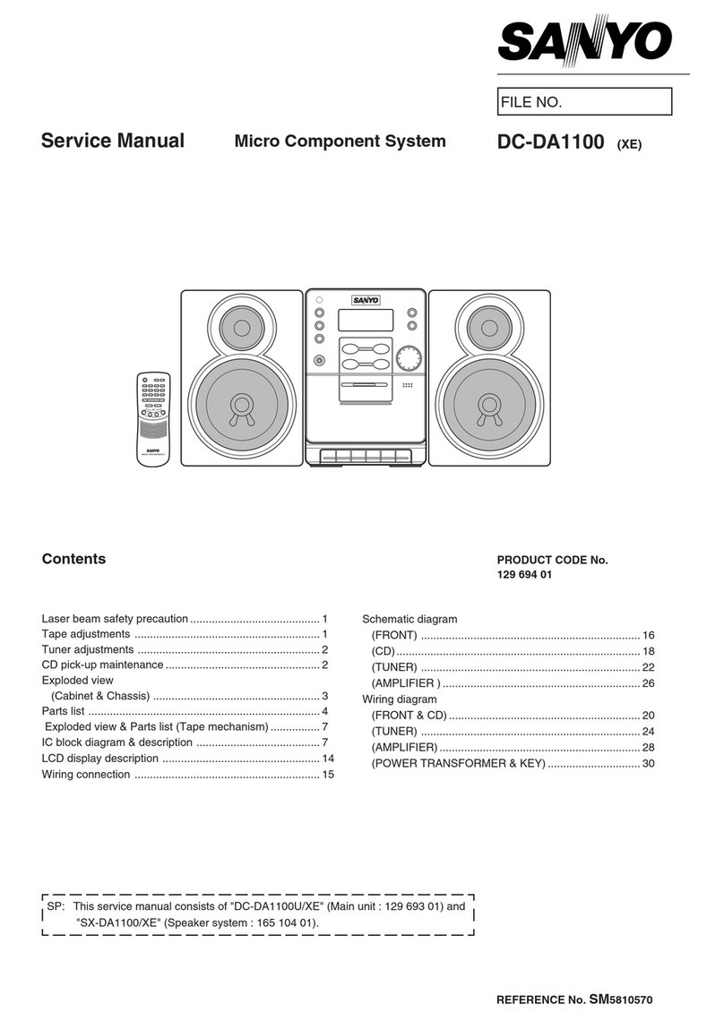
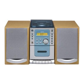
Sanyo DC-PT80 User manual

FILE NO.
Service Manual
CONTENTS
DVD Micro System DC-PT80 (ZA)
PRODUCT CODE No.
129 710 08
REFERENCE No. SM5810746
Laser beam safety precaution .......................................... 1
DVD Mechanism replacement ......................................... 2
Mechanism Replacement ................................................ 3
Wiring Connection ........................................................... 5
Service mode ................................................................... 6
Tuner Adustment ............................................................. 9
Exploded View (Cabinet & Chassis : Main) ..................... 11
Parts List .......................................................................... 12
Exploded View (DVD Mechanism) ................................... 16
Parts List .......................................................................... 16
IC Block Diagram & Description ....................................... 17
Schematic Diagram .......................................................... 28
Wiring Diagram ............................................................... 36
REMOTE CONTROLLER RB-PT50RDS

- 1 -
LASER BEAM SAFETY PRECAUTION
• Pick-up that emits a laser beam is used in this CD player section.
CAUTION :
USE OF CONTROLS OR ADJUSTMENTS
OR PERFORMANCE OF PROCEDURES
OTHER THAN THOSE SPECIFIED HEREIN
MAY RESULT IN HAZARDOUS RADIATION
EXPOSURE
LASER OUTPUT.......... 0.6 mW Max. (CW)
WAVELENGTH ............. 790 nm
CLASS 1 LASER PRODUCT
LUOKAN 1 LASERLAITE
KLASS 1 LASERAPPARAT
CAUTION –IN VISIBLELASERRADIA TIONWHENOPENAND
INTERLOCKSDEFEA TED.A VOIDEXPOSURETOBEAM.
ADVARSEL –US YNLIGLASERSTR ÅLINGVED ÅBNING,N ÅR
SIKKERHEDSAFBRYDEREERUDEAFFUNKTION,UNDG ÅUD S ÆTTELSE
FORSTR ÅLING.
VARNING –OS YNLIGLASERSTR ÅLNINGN ÄRDENNADEL ÄR ÖPPNAD
OCHSP ÄRR ÄRURKOPPLAD.STR ÅLEN ÄRF ARLIG.
VORSICHT –UN SICHTBARELASERSTRAHLUNGTRITTAUS,WENN
DECKELGE ÖFFNETUNDWENNSICHERHEITSVERRIEGELUNG
ÜBERBRÜCKTIST.NICHT,DEMSTRAHLAUSSETZEN.
VARO –A VATTAESSAJASUOJALUKITUSOHITETT AESSAOLETAL TTIINA
NÄKYMÄTTÖMÄLLELASERS ÄTEILYLLE. ÄLÄKA TSOS ÄTEESEEN.

- 2 -
1. Cautionary instructions in handling the assy
(Safety instructions)
Optical pickup
The laser beam used in the pickup is classified as "class 2".
Exposing your eyes or skin to the beam is harmful. Take care
not to do so.
(Caution against static electricity and leakage voltage)
Ground securely the work tables, tools, fixtures, soldering irons
(including those made of ceramic) and measuring instruments
used in the production lines and inspection departments that
handle loaders. The workers shall also be grounded.
(Cautionary instructions in handling)
Do not touch the object lens when handling a loader, or the lens
will be stained, resulting in inadequate playability.
There is no power supply protection circuit provided for this
product or adjustment/inspection device. Short-circuiting may
lead to fire or damage.
Take care so as to protect from exposure to water, the entry of
metallic pieces or dew condensation.
In particular, a strong magnet adjacent to the pickup will not only
get inoperative but can damage the pickup if a small metallic
piece, such as a screw or swarm, enters.
The loader edge can cause injury if inadvertently handled.
Do not touch a rotating disk, or injury may result.
This product is a precision device. Handle carefully.
A shock or dropping will cause misalignment or destruction. If it
should occur, refer to clause 2.
This product is so designed as to endure an initial shock
equivalent to a drop from a height of approx. 90 cm under the
packed condition.
After the initial shock, the resistivity will still remain at a level of
50 to 60 G, but the mechanical robustness will weaken.
Do not place in a dusty location.
The entry and deposition of dirt into or on the pickup lens or
moving section will cause malfunction or degradation.
DVD MECHANISM REPLACEMENT
(Connectors)
Do not connect or disconnect while power is on.
Connecting or disconnecting signal wires or the main power cord
when the power is on may destruct the unit or fixture.
When connecting, push all the way in securely.
An insufficient insertion may cause a bad contact, leading to an
erroneous operation.
Do not connect or disconnect roughly by an excessively strong
force, or a broken wire or bad contact may result.
Semiconductors are connected. Do not touch connector terminals
directly.
If the worker is grounded, there is nothing to worry about static
electricity, but the rust on the connector terminal surface caused
by the touch may result in bad contact.
(Caution)
Before disconnecting FFC
cable, make it "SHORT" as
shown left.
After connecting FFC
cable,make it "OPEN" as
shownleft.
(Power source)
The power source need be good in quality (free from
instantaneous interruptions or noises).
A low quality power source may well cause malfunction.
(Storage)
Do not place or store in a dusty place or a place where dew
condensation is possible.
The entry and deposition of dirt or dust into or on the pickup lens
or moving section will cause malfunction or degradation.
Also, dew condensation causes rust; the rust penetrate into the
precision part of a pickup, causing malfunction, or degrading the
optical quality of the internal lens and reflector, which also leads
to malfunction.
(OPEN)(SHORT)
1. How to Remove DVD Mechanism
First, it is necessary to remove Escutcheon.
How to remove Escutcheon.
An eject button is pushed and a tray is taken out.
Please remove Escutcheon, as shown in the left figure 2 .
When an eject button 1 does not function. Above figure
Please insert a cylindrical thing with a diameter of 3mm or less
in the hole 3 in the side of a DVD mechanism.
A tray is pushed out.
MECHANISM REPLACEMENT
1
1
1
2
Escutcheon
A figure of reference.
3
Side of DVD mechanism
Front Rear
Cylindrical thing
- 3 -
MECHANISM REPLACEMENT
2. How to remove the tray.
3. How to insert the tray.
1
2
1
1
2
Rotatethe1gear.
Moveforwardthe2tray.
Moveboththerightandleft1traypinstotheends.
Removethe2tray.
Movethe1slidetotheleftend.
Insertthe2tray.
21
3
1

- 4 -
G-SANKOL CFD-409Z
or
G-HANARL SF-106B
G-S
A
G-H
A
G-SANKOL CFD-409Z
or
G-HANARL SF-106B
6. Base mechanism mounting parts. 8. Tray parts.
MECHANISM REPLACEMENT

- 5 -
WIRING CONNECTION
CN605
(5P)
CN601
(13P)
CN602
(8P)
CN001
(5P)
LCD61
CN874
(9P)
CN873
(8P)
CN112
(3P)
C6130
(6P)
C6120
(24P)
CN871CN876CN870 CN872
VIDEO
OUT S-VIDEO
OUT
COMPONENT
VIDEO OUT DIGITAL
AUDIO OUTPUT CN470
(6P)
CN475
PHONES
CN420
(9P)
CN251
(9P)
CN450
(9P)
CN400
(13P)
CN490
(2P)
CN442
WR491
BL
WR490
BW
CN401
EXT. ANT
LINE IN
FM
EXT.
AM
LOOP
CN201
LR
L-CH
SPEAKER
BOX
R-CH
SPEAKER
BOX
TUNER P.W.B
AMP-DG P.W.B
FRONT P.W.B
LOADING
MOTOR
P. W. B
PICK UP
MOTOR
P. W. B
PICK UP
P. W. B
DVD P.W.B HP P.W.B
DVD MECHANISM
AC IN
CN491
(2P)
CN440
(6P)
P. T
CN610
CN460

- 6 -
SERVICE MODE
Region1 MarketWM
Back end Version
S40723A0
LoaderVersion 03.01.20.28
of Service mode displayVersion
Vaddis
6
Screen of Iinternal Setup
Internal Setup
Market WM
Region 1
Exit
00-WM 01-SFC 02-CA 03-EUR 04-EUS
05-EUC 06-DER 07-DES 08-DEC 09-AU
10-SS 11-PA 12-NTX 13-CN 14-JP
00
Market Setting
Internal Setup
Market 00
Region 1
Exit
00-WM 01-SFC 02-CA 03-EUR 04-EUS
05-EUC 06-DER 07-DES 08-DEC 09-AU
10-SS 11-PA 12-NTX 13-CN 14-JP
13
A. Market / Region SETUP
In the initial condition for this model, Market and Region
information are undefined.
In the following cases, be sure to set up Market/Region.
1. When updating the system using CD-R
(Part code : 0PRADC9709---AH).
2. When replacing a DVD substrate.
While Market/Region information are undefined,
the message "Region Undefined" is displayed on the screen.
NOTE: Even if the condition is not under 1 or 2 above, if the
message "Region Undefined" is displayed, be sure to
set up Market/Region.
B. How to enter Service Mode.
1. Using the buttons on the main unit
1-1. Display on "No Disc" by Function button.
1-2. Immediately (within one second) after pushing
stop button both and power buttons
simultaneously , push play button.
RegionUndefined
Undefined Market/Region display
C. Setup Procedures
1. Displaying SERVICE MODE screen
Display Service Mode screen following the instructions
"How to enter Service Mode" above.
2. Displaying Internal Setup screen
Push PRESET+/NEXT button within three seconds
after operating the
Service Mode display.
On the Internal Setup screen shown on the right,
set up Market and Region.
3.1. While a highlighted indicator is displayed on the right
side of the Market denotation, push numeric buttons
on the remote controller.
When you push wrong number , push CLEAR button.
(The indicator reset to "00")
Be sure to input by double figures.
This model is "10"
3.2. Specify the code of the model in accordance with the
Market/Region Setup Table above.
3.3 Once the desired code is displayed, push button to
move the highlighted indicator to the Region input area.

- 7 -
SERVICE MODE
Region Setting
Internal Setup
Market 00
Region 1
Exit
00-WM 01-SFC 02-CA 03-EUR 04-EUS
05-EUC 06-DER 07-DES 08-DEC 09-AU
10-SS 11-PA 12-NTX 13-CN 14-JP
1
Internal Setup
Market 00
Region 1
00-WM 01-SFC 02-CA 03-EUR 04-EUS
05-EUC 06-DER 07-DES 08-DEC 09-AU
10-SS 11-PA 12-NTX 13-CN 14-JP
Exit
Save of Setting Data
Region1 Market
WM
Back end Version S40726A6
LoaderVersion 03.01.20.28
SettingVersion of
display
Vaddis6
4. Setting REGION code
4.1 While a highlighted indicator is displayed on the right
side of the Region denotation, push ENT, and each
button on the remote controller. With each push the
indicator will advance as shown below.
1 <-> 2 <-> 3 <-> 4 <-> 5 <-> 6
4.2 Set up the region coder currently displayed on the set.
4.3 Once the desired number is displayed, push button to
move the highlighted indicator to Exit area.
5. Saving settings
5.1 Make sure that the Market and Region settings are
properly set.
(If any of the settings are incorrect, you can make a
change by moving the indicator using button, and
following procedures 3 and 4 above. )
5.2 After ensuring that the settings are all correct, push
ENT button while the indicator is on Exit area.
The settings are now saved.
6. Finishing settings
6.1 After a few seconds, the Internal Setup screen
disappears, and then the Service Mode screen is
displayed again for three seconds as shown on the right.
You should check the settings.
6.2 Power OFF.
Backendversion S 40726 A 6
Brand (S : SANYO , F : FISHER)
Version ( 2 0 0 4. 7. 26 )
Sub Version (A,B,......Z)
Region ( 0 : Region undefined
1 ~ 6 : Region defined )
The region coder of this model is 2.
4.2 Set up the region coder currently displayed on the set.4.2 Set up the region coder currently displayed on the set.

- 8 -
SERVICE MODE
IMPORTANT NOTE
1.Once the "Market information" is written into EEPROM (IC818) on the DVD board,"Market information" can not be modified.
(However, updating the system software using CD-R enables you to make new settings.)
2.You can exit from "Market information setup" by pushing POWER button or OPEN/CLOSE button. All the changes on the
Internal Setup screen are abandoned. "Market information setup" should be proceeding once again.
HOW TO LOAD SOFTWARE FOR SYSTEM Microcomputer
1. Power on and select DVD/CD function.
2.Open the tray.
3.Locate the system software update CD on the tray, and then close the tray.
4.About 50 seconds later from the tray closed, "Start to update MPEG flash memory. PLEASE DO NOT UNPLUG THE
POWER CODE. " will be displayed on the TV screen.
"UPDATING" will be displayed on the VFD.
5. When software loading complete, the player becomes STANDBY mode automatically.
6. Setup the "Market information" by following the instruction above.
CD-R part code is"0PRADC9709---AH".
CAUTION
After replacing the DVD P.w.Board ASSY (Parts code : 614 331 3397) should update both SYSTEM microcomputer software
and AUDIO DSP software using latest update CD-R respectively.
After replacing IC ASSY (Parts code : 410 530 9907) should update SYSTEM microcomputer software using latest CD-R for
SYSTEM microcomputer.

- 9 -
TP13
TP15
TP14
TP11(H)
TP12(H)
GND
TP24
TP25 TP26
CT252
L2151
L2153
T2002
XF233
TUNER ADJUSTMENT

- 10 -
TUNER ADJUSTMENT
1. TUNER ALIGNMENT SPECLIST
POWER SUPPLY VOLTAGE CN:220V,50Hz KR:220V,60Hz ,AU:240V,50Hz SS:115/230V/50/60Hz
FM
STANDARD CONDITION
ANTENNA : 75ohm UNBALANCED DIRECT
MOD. FREQ. : 1kHz
DEVIATION : MONO ±22.5kHz / STEREO ±22.5kHz(MAIN), ±6.75kHz (PILOT)
RF LEVEL : dBµV EMF
OUTPUTLEVEL : about 100mV at TP13,TP14,TP15
ITEM FREQ. INPUT OUTPUT ALIGNMENT
IF(0V)
ALIGNMENT
98.0MHz
FM ANT.(H)
FM ANT.(E)
SG=66dBµV
IC231
3 - 22PIN
TP24,25
Alignment Parts is XF233
Alignment Voltage(IC231 3-22PIN) is 0.0±0.05V
87.5MHz
CHECK VT voltage of 87.5MHz is about1.3±0.5V ..
COVER
VOLTAGE
108.0MHz
TP11(H)
TP12(E)
Confirm voltage of 108.0MHz is about 7.2V.(<8.0V)
90.0MHz
TRACKING
106.0MHz
FMANT.
SG 8dBµV
TP13(L)
TP14(R)
TP15(E)
AUTO STOP
98.0MHz
FM ANT.(H)
FM ANT.(E)
STSENS.
98.0MHz
FM ANT.(H)
FM ANT.(E)
SEPARATION
98.0MHz
FM ANT.(H)
FM ANT.(E)
SG=66dBµV
TP13(L)
TP14(R)
TP15(E)
AM
STANDARD CONDITION
ANTENNA : IRE LOOP(SG) <-- 60cm <--1AV0L90B00500(SET)
MODURATION : 1kHz,30%
RF LEVEL : dB µV EMF
OUTPUT LEVEL : about 100mV at TP13,TP14,TP15
ITEM FREQ. INPUT OUTPUT ALIGNMENT
IF
ALIGNMENT
522kHz
LOOP ANT.
IC231
19
PIN_DCCUT
(TP26) GND
Alignment Parts is T2002
Adjust T2002 to become waveform like this or
output signal max.
COVER Voltage 522kHz
TP11(H) Alignment Parts is L2153
Alignment voltage of 522kHz is 1.0V±0.1V.
1611 kHz
TP12(E) Confirm voltage of 1611kHz is about 7.1V.(<8.0V)
603kHz
Alignment Parts is L2151
Adjust L2151 to become output signal max.
TRACKING
1404kHz
LOOP ANT
SG 80dB
µV/m
TP13(L)
TP14(R)
TP15(E)
Alignment Parts is CT252
Adjust CT252 to become output signal max.
AUTO STOP 999kHz
LOOP ANT
Confirm AUTO STOP SENS.
If AUTO STOP SENS.is bad,readjust T2002,L2151and CT252.
Max.
Max.
Max.
Max.

- 11 -
EXPLODED VIEW (CABINET & CHASSIS : Main)
12
17
18
17
18
6
Y02
Y03
Y03
Y04
Y08 Y08
Y06
Y08
Y08
Y06
Y07
Y07
Y07
Y10
Y12
Y13
Y14
Y14
Y14
Y14
Y18
Y10
Y01
8
9
11
51
52
53
72
71
59
54
55
56
57
75
58
13
73
74
12
17
15
16
10
7
3
: Not available as service parts.
This is a basic exploded view.

- 12 -
REF.NO. PART NO. DESCRIPTION
PARTS LIST
PRODUCT SAFETY NOTICE
EACH PRECAUTION IN THIS MANUAL SHOULD BE FOLLOWED DURING SERVICING. COMPONENTS IDENTIFIED WITH THE
IEC SYMBOL !
!! IN THE PARTS LIST AND THE SCHEMATIC DIAGRAM DESIGNATED COMPONENTS IN WHICH SAFETY AND
PERFORMANCE CAN BE OF SPECIAL SIGNIFICANCE. WHEN REPLACING A COMPONENT IDENTIFIED BY !
!! , USE ONLY THE
REPLACEMENT PARTS DESIGNATED, OR PARTS WITH THE SAME RATINGS OF RESISTANCE, WATTAGE OR VOLTAGE THAT
ARE DESIGNATED IN THE PARTS LIST IN THIS MANUAL. LEAKAGE-CURRENT OR RESISTANCE MEASUREMENTS MUST BE
MADE TO DETERMINE THAT EXPOSED PARTS ARE ACCEPTABLY INSULATED FROM THE SUPPLY CIRCUIT BEFORE
RETURNING THE PRODUCT TO THE CUSTOMER.
CAUTION :Regular type resistors and capacitors are not listed. To know those values, refer to the schematic diagram.
Regular type resistors are less than 1/4 W carbon type and chip resistors.
Regular type capacitors are less than 50 V and less than 1000 µF type of Ceramic type and Electrical type.
PACKING & ACCESSORIES
REF.NO. PART NO. DESCRIPTION
17 614 333 1193 ASSY,GRILLE
18 614 333 1186 ASSY,BOX,SPEAKER
645 036 4334 POLY SHEET-0750X0400*NC,SET
645 052 1416 POLY BAG-0150X0300*NC,
AC CORD
614 331 4318 CUSHION,REAR,REAR
614 331 4301 CUSHION,FRONT,FRONT
645 066 9330 CABLE,VIDEO,CABLE,VIDEO
645 069 4127 REMOCON,RB-PT50
614 245 0055 ANTENNA,FM ANTENNA
645 046 8322 ASSY,ANTENNA,LOOP,
AM ANTENNA
614 334 1536 CARTON CASE,UNIT
614 334 1598 INSTRUCTION MANUAL,INST
645 066 4410 POLY BAG-0250X0350*NC,
INST MANUAL
645 072 9003 POLY BAG-0170X0300*NC,
ACCESSORY
!
!! 645 067 3870 PLUG,ADAPTOR AC,
PLUG ADAPTOR AC
or !
!! 645 006 4630 PLUG,ADAPTOR AC,
PLUG ADAPTOR
CABINET & CHASSIS
REF.NO. PART NO. DESCRIPTION
1 614 331 4202 KNOB,VOLIME,JOG VOLUME
2 614 331 4141 DEC,RING,VOL,RING VOL
3 614 331 3878 ASSY,CABINET,FRONT
7 614 331 4066 CAP,BUTTON,DVD,CAP
8 614 331 4028 BUTTON,DVD,DVD BUTTON
9 614 331 4011 BUTTON,FUNCTION,
FUNCTION BUTTON
10 614 331 4004 BUTTON,POWER,POWER
11 614 333 4767 ASSY,CABINET,BOTTOM
13 614 331 3908 ASSY,DEC,DVD,TRAY
15 614 334 0256 PANEL,REAR,REAR
16 614 331 4035 CABINET,TOP/SIDE
17 614 331 4172 HOLDER,DVD,PWB,DVD& PWB
FIXING PARTS
REF.NO. PART NO. DESCRIPTION
Y01 411 193 8603 SCR S-TPG BRZ+FLG 3X10,
HEAD PH0NE
Y02 411 194 1009 SCR S-TPG BIN 2X8,FRONT PANEL
Y03 411 021 3404 SCR S-TPG BIN 3X10,FRONT PWB
Y04 411 202 7702 SCR S-TPG BRZ+FLG 3X8,
DVD MECHA
Y06 411 196 5609 SCR S-TPG BIN 3X6,LUG
Y07 614 130 0382 LUG,FRONT HEADPHONE WIRE
Y08 411 098 1006 SCR S-TPG BIN 3X6,
HOLDER DVD PWB
Y10 411 098 4205 SCR S-TPG BIN 3X8,
AMP PWB TUNER PWB
Y12 411 202 7702 SCR S-TPG BRZ+FLG 3X8,
POWER TRAINS
Y13 411 195 3804 SCR S-TPG BIN 3X10,
REAR HOLDER
Y14 411 195 3804 SCR S-TPG BIN 3X10,
REAR-ELECT PART
Y18 411 195 3804 SCR S-TPG BIN 3X10,
BOTTOM-REAR
ELECTRICAL-PARTS
REF.NO. PART NO. DESCRIPTION
6!
!! 614 332 0944 PWB,HP-STOPPER
51 645 069 3991 FLEXIBLE FLAT CABLE,FRONT-AMP
52 614 331 3953 ASSY,WIRE,FRONT-DVD
53 614 331 3946 ASSY,WIRE,FRONT-MECHA
54 614 331 3960 ASSY,WIRE,DVD-MECHA
55 645 069 4295 FLEXIBLE FLAT CABLE,
DVD-MECHA
56 614 331 3984 ASSY,WIRE,AMP-HP
57 614 331 3977 ASSY,WIRE,AMP-DVD
58 !
!! 645 069 3984 TRANS,POWER
59 !
!! 645 063 0255 CORD,POWER-1.76MK
645 051 0656 CORE,FERRITE,FOR AMP-HP
or 645 042 8999 CORE,FERRITE,FOR AMP-HP
645 051 0656 CORE,FERRITE,FOR FRONT-DVD
or 645 042 8999 CORE,FERRITE,FOR FRONT-DVD
614 129 9136 LUG,POWER TRANS WIRE
HP P.W.BOARD ASSY
REF.NO. PART NO. DESCRIPTION
71 614 331 1720 ASSY,PWB,HP(Only initial)
C4701 403 157 6909 CERAMIC 820P K 50V
C4750 403 215 2201 CERAMIC 0.01U K 50V
C4751 403 157 6909 CERAMIC 820P K 50V
CN470 614 310 2625 PLUG,6P
or 645 006 0939 PLUG,6P
CN475 645 011 6384 JACK,PHONE D3.6,HEADPHONE
or 645 055 1017 JACK,PHONE D3.6,HEADPHONE
L4700 645 002 1459 INDUCTOR,22U K
L4701 645 045 7869 IMPEDANCE,1000 OHM P
or 645 020 1813 INDUCTOR,1000 OHM
or 645 034 7887 INDUCTOR,1000 OHM
L4720 645 045 7869 IMPEDANCE,1000 OHM P
or 645 034 7887 INDUCTOR,1000 OHM
or 645 020 1813 INDUCTOR,1000 OHM
L4750 645 002 1459 INDUCTOR,22U K
L4751 645 034 7887 INDUCTOR,1000 OHM
or 645 045 7869 IMPEDANCE,1000 OHM P
or 645 020 1813 INDUCTOR,1000 OHM
FRONT P.W.BOARD ASSY
REF.NO. PART NO. DESCRIPTION
72 !
!! 614 330 9796 ASSY,PWB,FRONT(Only initial)
BRC60 614 331 4073 COVER,LED,COVER_LED
BRH60 614 331 4189 HOLDER,LCD,HOLDER_LCD
BRS60 614 331 4165 DEC,SHEET,LCD,DEC_SHEET_LCD
CN601 645 070 8879 SOCKET,FFC 13P
CN602 614 310 2649 PLUG,8P
or 645 075 4609 PLUG,8P
CN605 614 310 2618 PLUG,5P
or 645 075 4579 PLUG,5P
CN610 614 332 0951 CORD,1P CONNECTOR,
FRONT-AMP

- 13 -
PARTS LIST
REF.NO. PART NO. DESCRIPTION
D6000 407 012 4406 DIODE 1SS133
D6050 407 012 4406 DIODE 1SS133
D6051 407 012 4406 DIODE 1SS133
D6052 407 012 4406 DIODE 1SS133
D6211 408 053 4004 LED LT0334-43-UBC1,AMBER_LED
D6212 408 053 4004 LED LT0334-43-UBC1,AMBER_LED
DS601 407 235 5006 PHOTO DIODE SPS-444-1-VG
IC601 410 570 6409 IC LC877B40A-55V6-E
IC602 410 448 8504 IC S524A40X21-SCB0
or 410 429 7908 IC AT24C02N-10SI-2.7
or 410 448 8405 IC S524A40X21-SCT0
IC603 409 575 1908 IC PST3645U
IC605 !
!! 409 441 4507 IC TA7291S(M)
L6010 645 001 4550 INDUCTOR,10U K
L6400 645 020 1882 INDUCTOR,1800 OHM
L6401 645 020 1882 INDUCTOR,1800 OHM
L6402 645 020 1882 INDUCTOR,1800 OHM
LCD61 645 070 6837 LCD
Q6050 405 143 0007 TR KRC107M
or 405 000 3806 TR DTC114YS
Q6051 405 008 2405 TR 2SB698-F
or 405 141 3703 TR KTA1271-Y
or 405 008 2504 TR 2SB698-G
Q6108 405 143 8706 TR KTC3199-GR
or 405 017 9709 TR 2SC3330-U
or 405 017 9600 TR 2SC3330-T
or 405 011 8609 TR 2SC1740S-S
or 405 011 8500 TR 2SC1740S-R
Q6211 405 143 0007 TR KRC107M
or 405 000 3806 TR DTC114YS
Q6212 405 143 0007 TR KRC107M
or 405 000 3806 TR DTC114YS
Q6213 405 159 0503 TR KRC107S
or 405 141 5608 TR DTC114YKA
Q6214 405 159 0503 TR KRC107S
or 405 141 5608 TR DTC114YKA
Q6270 405 000 3806 TR DTC114YS
or 405 143 0007 TR KRC107M
Q6271 405 143 6504 TR KTA1267-GR
or 405 004 4601 TR 2SA608-F-SPA
or 405 004 5103 TR 2SA608-G-SPA
or 405 006 1806 TR 2SA933S-R
or 405 006 1905 TR 2SA933S-S
R6050 !
!! 402 082 0709 RESISTOR 5.6 J- 2W
or !
!! 402 072 0207 RESISTOR 5.6 J- 2W
S6001 645 069 4264 SWITCH,ROTARY(ENCODER)
S6110 614 220 5471 SWITCH,TACT
or 614 240 1002 SWITCH,TACT
or 645 006 5958 SWITCH,PUSH 1P-1T
S6111 614 220 5471 SWITCH,TACT
or 614 240 1002 SWITCH,TACT
or 645 006 5958 SWITCH,PUSH 1P-1T
S6112 645 006 5958 SWITCH,PUSH 1P-1T
or 614 240 1002 SWITCH,TACT
or 614 220 5471 SWITCH,TACT
S6113 645 006 5958 SWITCH,PUSH 1P-1T
or 614 240 1002 SWITCH,TACT
or 614 220 5471 SWITCH,TACT
S6114 645 006 5958 SWITCH,PUSH 1P-1T
or 614 240 1002 SWITCH,TACT
or 614 220 5471 SWITCH,TACT
S6115 645 006 5958 SWITCH,PUSH 1P-1T
or 614 240 1002 SWITCH,TACT
or 614 220 5471 SWITCH,TACT
S6210 614 220 5471 SWITCH,TACT
or 614 240 1002 SWITCH,TACT
or 645 006 5958 SWITCH,PUSH 1P-1T
S6211 614 220 5471 SWITCH,TACT
or 614 240 1002 SWITCH,TACT
or 645 006 5958 SWITCH,PUSH 1P-1T
S6212 614 220 5471 SWITCH,TACT
or 614 240 1002 SWITCH,TACT
or 645 006 5958 SWITCH,PUSH 1P-1T
S6213 614 220 5471 SWITCH,TACT
or 645 006 5958 SWITCH,PUSH 1P-1T
or 614 240 1002 SWITCH,TACT
S6214 645 006 5958 SWITCH,PUSH 1P-1T
or 614 240 1002 SWITCH,TACT
or 614 220 5471 SWITCH,TACT
S6215 645 006 5958 SWITCH,PUSH 1P-1T
or 614 240 1002 SWITCH,TACT
or 614 220 5471 SWITCH,TACT
SG601 645 055 3202 SURGE-ABSORBER
SG602 645 055 3202 SURGE-ABSORBER
SG603 645 055 3202 SURGE-ABSORBER
SG604 645 055 3202 SURGE-ABSORBER
X6000 645 032 1627 OSC,CRYSTAL 32.768KHZ,XTAL
X6102 645 053 4393 OSC,CERAMIC 8.00MHZ,8MHZ
or 645 059 1570 OSC,CERAMIC 8.00MHZ,8MHZ
REF.NO. PART NO. DESCRIPTION
DVD P.W.BOARD ASSY
REF.NO. PART NO. DESCRIPTION
73 614 331 3397 ASSY,PWB,DVD(Only initial)
C8535 !
!! 403 373 7902 ELECT 150U M 6.3V
C8589 !
!! 403 373 7902 ELECT 150U M 6.3V
CN112 614 310 2595 PLUG,3P
or 645 075 4555 PLUG,3P
CN120 645 069 5032 SOCKET,FPC 24P
CN130 614 310 2625 PLUG,6P
or 645 075 4586 PLUG,6P
CN870 645 037 3831 JACK,RCA
CN871 407 239 3503 PHOTO COUPLE TX179AM
CN872 645 044 9086 SOCKET,DIN 4P
CN873 614 310 2649 PLUG,8P
or 645 075 4609 PLUG,8P
CN874 614 310 2656 PLUG,9P
or 645 075 4616 PLUG,9P
CN876 645 072 1410 JACK,RCA-3
or 645 072 1083 JACK,RCA-3
D1200 407 179 1805 DIODE DAP222
or 407 221 1807 DIODE KDS120E
IC110 410 556 0407 IC ZR36768HQCG-V
or 410 556 0506 IC ZR36768HQCG-W
IC120 409 625 9205 IC ZR36707TQCG
IC130 409 438 7207 IC BA5954FP
IC131 409 168 9106 IC BA10358F
IC132 409 168 9106 IC BA10358F
IC141 410 530 7804 IC M12L16161A-7TG
or 410 470 5007 IC M12L16161A-7T
or 410 453 9602 IC LC3816161ET70MP
IC142 410 530 7804 IC M12L16161A-7TG
or 410 470 5007 IC M12L16161A-7T
or 410 453 9602 IC LC3816161ET70MP
IC171 409 505 0803 IC PST3627U
IC172 410 429 7908 IC AT24C02N-10SI-2.7
or 410 448 8504 IC S524A40X21-SCB0
or 410 448 8405 IC S524A40X21-SCT0
IC818 410 530 9907 IC ASSY(IC LE28DW8163T-70T,
SST39VF800704CE,
SST39VF800A704C,
SST39VF800A-70-4C-EK,D)
IC851 !
!! 409 608 0908 IC UPC37M31TJ-AZ
IC852 !
!! 409 612 1403 IC PQ050DZ01Z
IC871 409 581 9400 IC PCM1755DBQ,DAC_2CH
IC881 409 543 6409 IC KRX101U
L1201 645 045 7869 IMPEDANCE,1000 OHM P
or 645 034 7887 INDUCTOR,1000 OHM
or 645 020 1813 INDUCTOR,1000 OHM
L1401 645 020 1813 INDUCTOR,1000 OHM
or 645 034 7887 INDUCTOR,1000 OHM
or 645 045 7869 IMPEDANCE,1000 OHM P
L1402 645 020 1813 INDUCTOR,1000 OHM
or 645 034 7887 INDUCTOR,1000 OHM
or 645 045 7869 IMPEDANCE,1000 OHM P
L8400 645 058 3315 INDUCTOR,1U M
L8410 645 058 3315 INDUCTOR,1U M
L8420 645 058 3315 INDUCTOR,1U M
L8440 645 040 6430 INDUCTOR,2.2U M

- 14 -
PARTS LIST
REF.NO. PART NO. DESCRIPTION REF.NO. PART NO. DESCRIPTION
L8582 645 045 7869 IMPEDANCE,1000 OHM P
or 645 034 7887 INDUCTOR,1000 OHM
or 645 020 1813 INDUCTOR,1000 OHM
L8701 645 045 7869 IMPEDANCE,1000 OHM P
or 645 034 7887 INDUCTOR,1000 OHM
or 645 020 1813 INDUCTOR,1000 OHM
Q1200 405 158 5905 TR KTA1505-Y
or 405 035 5509 TR 2SA1036K-R
Q1201 405 158 5905 TR KTA1505-Y
or 405 035 5509 TR 2SA1036K-R
Q1202 405 146 2206 TR KTC3875-GR
or 405 146 2107 TR KTC3875-Y
or 405 011 1006 TR 2SC1623-L6
or 405 014 4509 TR 2SC2412K-R
Q1204 405 011 1006 TR 2SC1623-L6
or 405 014 4509 TR 2SC2412K-R
or 405 146 2107 TR KTC3875-Y
or 405 146 2206 TR KTC3875-GR
Q1205 405 146 2206 TR KTC3875-GR
or 405 146 2107 TR KTC3875-Y
or 405 011 1006 TR 2SC1623-L6
or 405 014 4509 TR 2SC2412K-R
SG872 645 055 3202 SURGE-ABSORBER
SG874 645 055 3202 SURGE-ABSORBER
SG875 645 055 3202 SURGE-ABSORBER
SG879 645 055 3202 SURGE-ABSORBER
SG880 645 055 3202 SURGE-ABSORBER
X1100 645 045 8293 OSC,CRYSTAL 27.000MHZ
AMP-DG P.W.BOARD ASSY
REF.NO. PART NO. DESCRIPTION
74 614 330 9802 ASSY,PWB,AMP-DG(Only initial)
C4134 403 058 4608 POLYESTER 0.15U J 50V
C4136 403 366 5205 ELECT 1000U M 16V
or 403 350 8403 ELECT 1000U M 16V
C4234 403 058 4608 POLYESTER 0.15U J 50V
C4236 403 366 5205 ELECT 1000U M 16V
or 403 350 8403 ELECT 1000U M 16V
C4801 !
!! 403 370 3402 ELECT 220U M 35V
C4803 !
!! 403 373 8305 ELECT 100U M 10V
C4823 403 329 5907 ELECT 3300U M 25V
C4906 403 325 9701 ELECT 4700U M 25V
C4907 403 325 0302 ELECT 2200U M 25V
CN400 645 070 8879 SOCKET,FFC 13P
CN401 645 064 8519 TERMINAL,SPEAKER 4P,SPEAKER
CN420 645 005 8141 PLUG,9P
or 614 310 2502 PLUG,9P
CN440 645 006 0939 PLUG,6P
or 614 310 2625 PLUG,6P
CN442 645 071 4573 JACK,RCA-2,RCA-2P
CN450 645 012 2743 SOCKET,DIP 9P
CN460 614 221 8273 TERMINAL
CN480 614 239 1839 TERMINAL
CN481 614 239 1839 TERMINAL
CN490 !
!! 645 075 3626 PLUG,2P
CN491 614 310 2731 PLUG,2P
or 645 004 2881 PLUG,2P
D4500 407 012 4406 DIODE 1SS133
D4501 407 012 4406 DIODE 1SS133
D4800 !
!! 408 044 6208 DIODE SB240L 19C2-105
D4801 407 099 5402 ZENER DIODE MTZJ6.2B
D4820 407 012 4406 DIODE 1SS133
D4851 407 099 6003 ZENER DIODE MTZJ9.1B
D4852 407 012 4406 DIODE 1SS133
D4900 !
!! 407 107 6001 DIODE RL203-BD80
D4901 !
!! 407 107 6001 DIODE RL203-BD80
D4902 !
!! 407 107 6001 DIODE RL203-BD80
D4903 !
!! 407 107 6001 DIODE RL203-BD80
D4905 !
!! 407 107 6001 DIODE RL203-BD80
D4906 !
!! 407 107 6001 DIODE RL203-BD80
HS401 614 331 7005 HEAT SINK,HEATSINK
IC441 409 614 0701 IC LC75348M-E
IC442 !
!! 409 612 2202 IC KIA6282K
IC480 !
!! 409 609 3908 IC SI-8050RD
L4150 645 002 1459 INDUCTOR,22U K
L4250 645 002 1459 INDUCTOR,22U K
L4500 !
!! 645 048 4469 INDUCTOR,22U
or !
!! 645 045 8613 INDUCTOR,10U
L4800 !
!! 645 048 4469 INDUCTOR,22U
or !
!! 645 045 8613 INDUCTOR,10U
L4801 !
!! 645 069 3977 INDUCTOR,165U
L4802 !
!! 645 045 8613 INDUCTOR,10U
or !
!! 645 048 4469 INDUCTOR,22U
L4900 !
!! 645 038 6053 INDUCTOR,181U
LUG1 645 006 4425 FIXER
LUG2 645 006 4432 FIXER
LUG3 645 006 4425 FIXER
PR482 !
!! 645 042 2676 PROTECTOR,2.5A 125V
Q4101 405 143 0007 TR KRC107M
or 405 000 3806 TR DTC114YS
Q4151 405 033 6805 TR 2SD1468S-S
or 405 033 6706 TR 2SD1468S-R
or 405 021 0600 TR 2SD1012-G-SPA
or 405 021 0204 TR 2SD1012-F-SPA
or 405 151 4400 TR KTD1303
Q4201 405 000 3806 TR DTC114YS
or 405 143 0007 TR KRC107M
Q4251 405 033 6805 TR 2SD1468S-S
or 405 033 6706 TR 2SD1468S-R
or 405 021 0600 TR 2SD1012-G-SPA
or 405 021 0204 TR 2SD1012-F-SPA
or 405 151 4400 TR KTD1303
Q4500 405 151 6107 TR KRA107S
or 405 141 5707 TR DTA114YKA
Q4501 405 141 5707 TR DTA114YKA
or 405 151 6107 TR KRA107S
Q4850 !
!! 405 147 2106 TR KTC3205-Y
Q4851 405 141 3307 TR KTC3198-GR
or 405 019 3804 TR 2SC536-G-NP
or 405 019 2708 TR 2SC536-F-NP
or 405 141 3208 TR KTC3198-Y
Q4890 405 019 3804 TR 2SC536-G-NP
or 405 019 2708 TR 2SC536-F-NP
or 405 141 3208 TR KTC3198-Y
or 405 141 3307 TR KTC3198-GR
Q4891 405 143 0007 TR KRC107M
or 405 000 3806 TR DTC114YS
Q4892 !
!! 405 009 5207 TR 2SB927-S
or !
!! 405 141 3604 TR KTA1273-Y
or !
!! 405 009 5306 TR 2SB927-T
Q4893 405 000 3806 TR DTC114YS
or 405 143 0007 TR KRC107M
R4822 !
!! 402 096 4106 FUSIBLE RES 27 JA 1/4W
SA401 411 098 4205 SCR S-TPG BIN 3X8
WR490 614 017 8203 TERMINAL BOARD
WR491 614 017 8203 TERMINAL BOARD
TUNER P.W.BOARD ASSY
REF.NO. PART NO. DESCRIPTION
75 614 330 9819 ASSY,PWB,TUNER(Only initial)
C2457 403 259 0508 NP-ELECT 1U M 50V
CN201 645 031 7910 TERMINAL
or 645 005 0695 TERMINAL,ANT
CN251 645 012 2743 SOCKET,DIP 9P
CT252 645 032 5663 TRIMMER,7PF
D2101 407 241 2907 VARACTOR DI SVC230
D2102 407 241 2907 VARACTOR DI SVC230
D2104 407 012 4406 DIODE 1SS133
D2153 407 241 3003 VARACTOR DI SVC348S
or 407 241 3102 VARACTOR DI SVC348T
D2301 407 099 5402 ZENER DIODE MTZJ6.2B
D2450 407 012 4406 DIODE 1SS133
D2451 407 012 4406 DIODE 1SS133
D2455 407 012 4406 DIODE 1SS133
IC211 409 016 0200 IC LA1186N-AUDIO
IC231 409 474 3201 IC LA1844ML
IC241 409 439 4502 IC LC72121M-D

- 15 -
PARTS LIST
REF.NO. PART NO. DESCRIPTION
L2102 645 018 0163 COIL,AIR
L2103 645 018 0255 COIL,AIR
L2104 645 002 1534 INDUCTOR,8.2U K
L2151 645 037 2377 TRANS,ANT,796KHZ
L2153 645 069 4882 TRANS,OSC,796KHZ
L2451 645 001 4581 INDUCTOR,100U K
L2901 645 004 0511 INDUCTOR,270U J
LUG21 645 006 4425 FIXER
Q2201 405 151 4202 TR KTC3193-O
or 405 151 4103 TR KTC3193-Y
or 405 016 0806 TR 2SC2839-E
Q2450 405 143 8706 TR KTC3199-GR
or 405 011 8500 TR 2SC1740S-R
or 405 011 8609 TR 2SC1740S-S
or 405 017 9600 TR 2SC3330-T
or 405 017 9709 TR 2SC3330-U
Q2451 405 000 2205 TR DTA144ES
or 405 146 1308 TR KRA104M
SG201 645 055 3202 SURGE-ABSORBER
SG202 645 055 3202 SURGE-ABSORBER
T2002 645 046 2023 FILTER,450KHZ
X2451 645 023 4965 OSC,CRYSTAL 7.2MHZ
XF211 614 252 1045 FILTER,LC
or 645 026 2975 FILTER,BP 108MHZ
or 645 059 0047 FILTER,BP
XF221 614 030 5074 I.F FILTER
or 614 231 0199 FILTER
or 645 010 7665 CERAMIC FILTER 10.70MHZ
or 645 054 1223 CERAMIC FILTER 10.70MHZ
XF222 614 030 5074 I.F FILTER
or 614 231 0199 FILTER
or 645 010 7665 CERAMIC FILTER 10.70MHZ
or 645 054 1223 CERAMIC FILTER 10.70MHZ
XF231 645 041 9324 CERAMIC FILTER 450KHZ
or 645 059 0054 CERAMIC FILTER 450KHZ
XF233 645 039 9923 TRANS,IF 10.7MHZ
or 645 040 9981 TRANS,IF 10.7MHZ

- 16 -
PARTS LIST
EXPLODED VIEW (DVD MECHANISM)
DM05
DM06
DM07
DM08
DM09
DM10
DM11
DM01
DM12
DM13
DM14
DM19
DM20
DM19
DM16
DM15 DM19
DM16
DM15
DM19
DM16
DM15
DM02
DM03
DM04
DM21
DM22
DVD MECHANISM CHASSIS
REF.NO. PART NO. DESCRIPTION
12 614 332 9442 ASSY,MECHA,LDR898 SA,
MECHANISM ASSY
DM01 614 325 0074 DISC,CHUCK DISC
DM02 645 051 4920 MAGNET(CHUCK),MAGNET CHUCK
or 645 054 0448 MAGNET(CHUCK),MAGNET CHUCK
DM03 614 325 4591 SLIDE,BASE UP/DOWN
DM04 411 020 0503 SCR PAN PCS 1.7X4,
LOADING MOTOR FIX
DM05 614 325 6021 BELT,SQUARE,LOADING
DM06 412 065 3603 SPECIAL SCREW 2.0X8.0,
PULLEY FIX
DM07 614 325 4584 PULLEY,LOADING RETARD PULLY
DM08 614 325 4492 GEAR,LOADING GEAR
DM09 614 329 6317 CHASSIS,LOADING CHASSIS
DM10 614 329 6348 TRAY,TRAY
DM11 645 057 4467 ASSY,MOTOR,LOADING,
LOADING MOTOR
or 645 057 4603 ASSY,MOTOR,LOADING,
LOADING MOTOR
DM12 614 325 0081 HOLDER,CHUCK HOLDER
DM14 411 021 3008 SCR S-TPG BIN 2.6X8,
PWB MECHA SW FIX
DM15 411 021 1608 SCR S-TPG BIN 2.6X10,BASE FIX
DM16 411 188 3200 WASHER Z 2.6X10X0.5,BASE FIX
DM19 614 332 9459 SPACER,MECHA,
BASE MECHA FLOATING
DM20 614 329 6324 MOUNTING,
BASE MECHA MOUNTING
DM21 614 329 4979 ASSY,MECHA,MSA100 BASE,
BASE MECHA
DM22 411 099 0503 SCR TPG PAN PCS 1.7X6,
TRAY STOPPER
MECH SW P.W.BOARD ASSY
REF.NO. PART NO. DESCRIPTION
DM13 614 326 1605 ASSY,PWB,MECHA SW,
MOTOR&SW PWB
CN001 614 310 2618 PLUG,5P,MOTOR&SW PWB CONNE
or 645 006 0922 PLUG,5P,MOTOR&SW PWB CONNE
S0001 645 057 1381 SWITCH,LEVER,MECHA SW

- 17 -
IC BLOCK DIAGRAM & DESCRIPTION
LCD61 LCD
26
DPL
DD DP1
12
(2)
(2)
(1)
(1)
34567COL 8
DP2 DP3 DP4
COM4
COM3
COM2
COM1
27 39
1
26
27 39
1
26
27 39
1
PIN
COM1
COM2
COM3
COM4
1
COM1
2
COM2
3
COM3
4
COM4
56
8C
8H
8B
7
8D
8L
8K
8A
8
8M
8N
8J
8I
9
8E
8G
8F
10
7C
7H
7B
11
7D
7L
7K
7A
12
7M
7N
7J
7I
13
7E
7G
7F
14
DP4
COL
15
6D
6L
6K
6A
16
6E
6G
6F
17
5D
5L
5K
5A
18
DP3
5E
5G
5F
19
4D
4L
4K
4A
20
DP2
4E
4G
4F
PIN
COM1
COM2
COM3
COM4
21
3D
3L
3K
3A
22
3E
3G
3F
23
2D
2L
2K
2A
24
DP1
2E
2G
2F
25
1D
1L
1K
1A
26
1E
1G
1F
27 28
1M
1N
1J
1I
29
1C
1H
1B
30
2M
2N
2J
2I
31
2C
2H
2B
32
3M
3N
3J
3I
33
3C
3H
3B
34
4M
4N
4J
4I
35
4C
4H
4B
36
5M
5N
5J
5I
37
5C
5H
5B
38
6M
6N
6J
6I
39
6C
6H
6B

- 18 -
IC BLOCK DIAGRAM & DESCRIPTION
IC201 ZR36707TQC(Read channel I/O)
DVDRFP
DVDRFN
RFSIN
MUX
ATT
ATOP
ATON
AIN
AIP
SIG R b7-4
ATT
4
RFC R b7-6
INPUT IMP SEL
2
SIG R b3
INPUT SEL
A
A
B
C
D
CD_A
B
CD_B
C
CD_C
D
CD D
PDC R b3
CD/DVD
MUX
GCA
GCA
GCA
GCA
GCA
GCA
GCA
GCA
W/LPF
W/LPF
W/LPF
W/LPF
SIG R b2-0
12dB is added
@high gain mode (CDR b5=1)
3
SIG R b2-0
12dB is added
@high gain mode (CDR b5=1)
4D
SUM
6dB is added
@high gain mode (CDR b5=1)
GCA
GCA
RFC R b2-0
3
CD _E
CD_F
12dB is added
@high gain mode (CDR b5=1)
GCA
GCA
RFC R b2-0
GCA
GCA
EQ
EQ
EQ
EQ
TRC R2 b3-0
3B
+/-4dB
4
Comp.
VC
TRC R2 b6-4
DPD EQ
33
TRC R b6
DPD COMP HYS ON
CD R b4
LD H/L
DVD PD
CD PD
CC R b5
APC SEL
DVD/CD
Dual A PC
LDON
CDLD
DVDLD
MEV
MEVO
MIN
MP
RFC R b5-4
INOUT IMP SEL
2
INPUT
BIAS
SSOUT
AGC
FCC R b6-0
FBC R b6-0 14
2
CA R b1-0
Env/Clamp
B+D
SUM
Amp.
A+C
Tenvb
2
CA R b3-2
SIGDET
Clamp & Env
Level
DAC
GCA +/-4dB
A+D
B+C
TOPHLD
TOPHLD
RESUM
+-3dB
CD R b5
High gain
PHASE
DETECTOR
PHASE
DETECTOR
AGCO
AGC BTM ENV
Tenvb
Pll
CTC R b5-4
MEVO SEL
2
MUX
Btm Env
Btm clamp
& clip
MUX
TOP HLD
TOP ENV
BTM HLD
BTM ENV
MRC R2 b7-0
droop rate
control
MRC R b6-4
Mirr Comp
ATT Level
ATT
ATT
MUX
MUX
ofset
MUX
MB
MLPF
GCA
Vref
CG R b5-4
Gain
CD R b7
LINKEN
LINK
CH R b7-6
Mirr Defect
Comp ATT
CONTROL
Signals
To each block
3
2
PDC R b3
CD/DVD TRC R2 b7
CP/CN
Low Inp
CFR b4
CEFDB
TRC R b5-0
TR offset
6
3
CF R b2-0
CE-ATT
CF R b3
CEPOL
LPE
ATT
Pol.sel
Buf (-12dB)
MUX LPE SUB Offset
cancel
CE R b4-0
CE offset
0+-8dB, 4bit
CTC R b3-0
CO gain
4
Offset
cancel GCA
4
70kHz
LPF
Offset
cancel
5
CTC R b7
BCA DET
CB R b3-2
2
PIO R b4-0
Ploffset
FOC R b7-4
FS gain
4
AGCO
PROGRAMMABLE
EQUALIZER
FILTER
DIFFERENTIATOR
FULL WAVE
REC TIFIER
CG R b1
OUTPUTINHIBIT
FNP
FNN
DIN
DIP
RFAC
AGC
CHARGE
PUMP
RFC R b3
AGC HOLD
CD R b6
HLDEN
BYP
RX
FE
LPF
Offset
cancel
GCA
TOPHLD
70kHz
CC R b4-0
FE offset
5
4
+/-6db 4bit
FOC R b3-0
FO Gain
PII
SEL
SEL
DAC
COMP
CB R b1-0
CB R b5-4
TE MAS sel
2
CGR b0
OUTPUT IN HIBIT
2
PI
TPH
CE
DFT
RFDC
MNTR
LPC
CP
TE
V125
SDEN
V25
VC
LCN
CN
SDATA
SCLK
V33
MIRR
VPA
VPB
VNA
VNB
CC R b7
DISK DET
MUX
V33 for Output buff
SERIAL PORT
REGISTER
CD R b3
CD R b2
VCI for servo
for Ploutput ref.
CFR b7-5
TR Gain
3
V25/3 V25/2
VC
for TE, FE & CE output ret.
GCA TE
RST
P1
FE
TE
CE
V25
V125
V25/3
PIO R b7-5
3
GCA
A2
B2
C2
D2
MON
SEL

- 19 -
IC BLOCK DIAGRAM & DESCRIPTION
IC130 BA5954FP(Motor driver)
OET2
OET1
+
+
THERMAL
SHUT DOWN -BY
STAND
SLED
+
12
13
14
10
11
6
7
5
4
3
2
1
8
9
19
15
17
16
18
21
20
23
22
24
26
25
28
27
DRIVER
ACTUATOR
DRIVER
ACTUATOR
DRIVER
DRIVER
LOADING
Vcc PV cc2 PV cc1
X2
X2
DET AMP.
DET AMP.
VINFC
CFCerr1
CFCerr2
V
VOSL
VNFFC
Vcc
PV
PGND
VOSL-
VOSL+
VOFC-
VOFC+ VOTK+
VOTK-
VOLD+
VOLD-
PGND
VNFTK
PV
BIAS
GND
V LD
CTKerr2
CTKerr1
V TK
STBY
SL+
IN
SL-V
IN
IN
IN
CC2
10K 20K
7.5K
7.5K
7.5K
10K
15K
Pre GND
PGND
PV
CC2
25K
10K
PGND
Vcc
CC1
CC1
PV
7.5K
20K 10K
Pin No. Pin name Function
1. VINFC Focus drive input
2. CFC err1 For connection of capacitor for the error amp filter
3. CFC err2 For connection of capacitor for the error amp filter
4. VINSL + Op-amp input (+) for the sled driver
5. VINSL - Op-amp input (-) for the sled driver
6. VOSL Op-amp output for the sled driver
7. VNFFC Focus driver feedback pin
8. V
CC
V
CC
9. PV cc1 Power V
CC
for sled driver block
10. PGND Ground for Sled Driver block
11. VOSL - Sled driver output (-)
12. VOSL + Sled driver output (+)
13. VOFC - Focus driver output (-)
14. VOFC + Focus driver output (+)
15. VOTK + Tracking driver output (+)
16. VOTK - Tracking driver output (-)
17. VOLD + Loading driver output (+)
18. VOLD - Loading driver output (-)
19. PGND Ground for Actuator driver block
20. VNFTK Tracking driver feedback pin
21. PV
CC
2 Power V
CC
for Actuator driver block
22. GND Ground
23. VINTK Loading driver input
24. CTKerr2 For connection of capacitor for the error amp filter
25. CTKerr1 For connection of capacitor for the error amp filter
26. VINTK Tracking driver input
27. BLAS Bias input
28. STBY Stand - By control
Table of contents
Other Sanyo Stereo System manuals

Sanyo
Sanyo DC -X1000MD User manual

Sanyo
Sanyo DC-007C User manual

Sanyo
Sanyo GCD 1500 (AU) User manual

Sanyo
Sanyo PH-DTA120 User manual

Sanyo
Sanyo DTA-100PA User manual

Sanyo
Sanyo DC-DA1450M User manual

Sanyo
Sanyo DC-SLIM3000 User manual

Sanyo
Sanyo MAJ-R70 User manual

Sanyo
Sanyo DC-AS1600DX/XE User manual

Sanyo
Sanyo DC-DA280 User manual