manuals.online logo
Brands
  1. Home
  2. •
  3. Brands
  4. •
  5. Sargent
  6. •
  7. Lock
  8. •
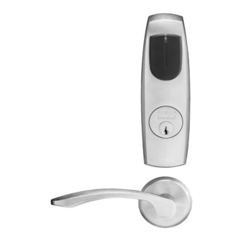
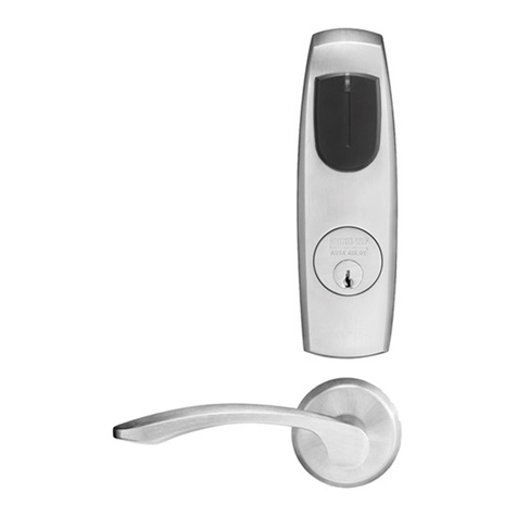
  9. Sargent ASSA ABLOY 10 Series User manual

Sargent ASSA ABLOY 10 Series User manual

1-800-727-5477 • www.sargentlock.com
A7133N 12/20
Copyright © 2020 SARGENT Manufacturing Company. All rights reserved. Reproduction in whole or
in part without the express written permission ofSARGENT Manufacturing Company is prohibited.
Installation Instructions
10 Line Cylindrical Lockset
Installation Instructions
• #2 Phillips screwdriver
1Package Contents
• Push pin (provided)
DOOR
FRAME
Desired height
from finished floor
Template
Backset must
match lock (2-
3/8" or 2-3/4'
Door bevel
Figure 1
a. Mark & Drill Holes b. Final Door Prep c. Frame Prep for Strike
• 1/8" drill bit
• 7/16" drill bit
• 2-1/8" Bore
•1" Bore
Figure 3
• Flat-bladed screwdriver
Figure 2
7/16" (11mm) hole
2-1/8"
(54mm)
hole
1-1/8"
(29mm)
2-1/4"
(57mm)
1" (29mm)
hole
5/32" (4mm)
Inside of Door
Outside of Door
(Secure Side)
12
34
56
7
8
4
2
9
10 11
12
13
14
16
17
15
Figure 4
Figure 1 Description Req
1 Inside Lever 1
2 Rose Scalp 2
3
Screws – mounting
plate #6 x 3/4" self-
tapping
2
4 Spacer bushing 2
5 Inside rose assembly 1
6Screws – through-
bolt #10-32 x 1-1/4" 2
7 Lockbody 1
8Outside rose
assembly 1
9 Cylinder spacer 1
10 Cylinder 1
11 Outside lever 1
12 Key 1
13 Push pin 1
14 Latch 1
15 Screws – latch &
strike #8-32 x 3/4" 4
16 Strike 1
17 Strike box 1
Tools Required
• All doors should be properly reinforced for lock support. If support is not provided, contact door manufacturer.
• For all metal door preparations, use template A4375 (Not included. See website to download), EXCEPT for functions 10G70 or 10G71
which use template 4409 (not included), or functions 10U93, 10U94, and 10U94-2 which require template A4375.
• For all wood door preparations use template A6719 (included), EXCEPT for functions 10G70 & 10G71.
• Template information is available on our website: www.sargentlock.com.
IMPORTANT: Deadlocking latch must
stop on the strike when the door is
closed.
#8-32 x 3/4"
Strike
Centerline of latch
front and strike
Screws (2)
Tighten after adjustment
IMPORTANT: Fold template onto high
edge of door bevel.
2Door Preparation
2
Copyright © 2020 SARGENT Manufacturing Company. All rights reserved. Reproduction in whole or in
part without the express written permission ofSARGENT Manufacturing Company is prohibited.
1-800-727-5477 • www.sargentlock.com A7133 12/20
10 Line
Installation Instructions
Cylindrical Lockset
Figure 5
Install screws (2) #8-32 x 3/4". Tighten after adjustment
Note: On doors without a beveled edge, the lock needs to be
adjusted to center the latch. Adjust per Section 5.
Presets:
• Through-bolt location: 12 and 6 o’clock. (Figure6)
• Door Thickness: 1-3/4" thick.
Figure 6
See step 10 for other door conditions
Outside
of Door
• Remove outside lever (usually keyed), rose and spacer bushing.
(Figure8)
• Rotate mounting plate to align with through-bolt holes in door, or
adjust mounting plate for proper door thicknesses (see markings
on Figure7).
• Reinstall spacer bushing to align with back of lever. Reinstall scalp
and lever.
• For doors 1 3/8" thick, use the 10-3188 adapter kit sold separately.
Confirm latch bolt front size.
Figure 7
Figure 8
Mounting plate
with through-bolts
Through-bolt
holes
Spacer bushing
1-3/4" thick door
2" thick door
NOTE: Test for proper
operation before closing
door.
3Latch Installation
4Install Outside Assembly
5Through-bolt and door thickness adjustment other than preset
6Install Inside Rose Assembly, Scalp and Lever
3
Copyright © 2020 SARGENT Manufacturing Company. All rights reserved. Reproduction in whole or in part
without the express written permission ofSARGENT Manufacturing Company is prohibited.
1-800-727-5477 • www.sargentlock.com A7133 12/20
10 Line
Installation Instructions
Cylindrical Lockset
To Remove:
Rotate key 45° and hold. Depress lever catch with pin tool.
To Install:
Insert key and rotate 45° clockwise, slide the lever on. Confirm the lever will not pull off.
Lever catch
To Remove:
Remove cylinder and tailpiece, using control key (stamped “C”). Insert Phillips #2 screwdriver into cylinder
opening and make contact with lever catch. Pull lever catch horizontally towards door hinge and remove
lever.
To Install:
Slide lever over lever catch. Confirm the lever will not pull off.
*Note: For 1-Bitted cylinders, utilize a control key cut 113511.
Figure 9
Control Key*
Figure 10
IMPORTANT
10G16, 10G30, 10G54 Functions:
• Before installing cylinders, use a flat-bladed screwdriver to rotate all cams
counterclockwise until they stop (Figure11). (Cam is located in lever support
tube of lockbody). (Figure12)
10G26 & 10G38 Functions:
• See supplemental instruction sheet A8082.
r
Key
Outside Lever
Correct Key Orientation
During Assembly
Cylinder
Cylinder
Spacer
Washers
(only 30-option)
Figure 11
Figure 12
Lever
Support
Tube
Cam
IMPORTANT
• Remove tailpiece from construction core and insert into new core. If using 7 pin cores,
insert the 7 pin tail piece that’s supplied with the lock, before installing the core into the lock.
• For Degree and XC LFIC cores, retainer must be installed on tailpiece.
C
C
New Cylinder
• Remove temporary construction core or plastic core. If keyed, use Control Key
(stamped “C”) rotate 15°and pull.
• Insert permanent core into lever with control key; rotate 15°and remove key.
Remove
Construction Core
Install New/
Final Cylinder
Remove/Reuse 6 Pin Tailpiece
Plastic Core
7 Pin
In Core
Keyed
Core
Construction Core
6 Pin
In Core
Keyed
Core
SFIC Shown
Standard Cylinder (Figure 9)
Interchangable or Removable Core (Figure 10)
Interchangeable or Removable Core
7Lever Removal & Installation
8Standard Cylinder Installation
A7133 12/20
SARGENT Manufacturing Company
100 Sargent Drive
New Haven, CT 06511 USA
800-727-5477
www.sargentlock.com
WARNING
This product can expose you to lead
which is known to the state of California
to cause cancer and birth defects or other
reproductive harm. For more information go
to www.P65warnings.ca.gov.
1. Remove 10G13 (Figure 13)
• Remove inside (non-rigid) lever with a standard push pin.
• Insert long push pin into lockbody tube and push to release spring-loaded lever
catch plug assembly for outside lever.
• Remove outside lever with lever catch plug assembly attached.
Figure 13
Figure 14
2 holes to align
with 2 tabs on rose
Scalp to be removed with
flat-bladed screwdriver
Rose
Screws (2) #6x3/4"
Cup
Washer
Screw
1/4x20
Figure 15
Scalp to be removed with
flat-bladed screwdriver
Rose
Tab
Screws (2)
#8-32x3/4"
Screws (2) 10-32x1/4"
Screws (2) #6 3/4"
2 holes to align
with 2 tabs on rose
10 Additional Installations
3. Install 10U94/10U94-2 (Figure 15)
2. Install 10U93 (Figure 14)

Other Sargent Lock manuals

Sargent PASSPORT 1000 Exit Device User manual

Sargent

Sargent PASSPORT 1000 Exit Device User manual

Sargent 7800 User manual

Sargent

Sargent 7800 User manual

Sargent ASSA ABLOY SE LP10 User manual

Sargent

Sargent ASSA ABLOY SE LP10 User manual

Sargent Profile Series User manual

Sargent

Sargent Profile Series User manual

Sargent IN220 Service manual

Sargent

Sargent IN220 Service manual

Sargent ASSA ABLOY IN Series User manual

Sargent

Sargent ASSA ABLOY IN Series User manual

Sargent Degree DG-2 User manual

Sargent

Sargent Degree DG-2 User manual

Sargent IN220 User manual

Sargent

Sargent IN220 User manual

Sargent ASSA ABLOY IDP-H1 User manual

Sargent

Sargent ASSA ABLOY IDP-H1 User manual
Sargent Passport 1000 P2 User manual

Sargent

Sargent Passport 1000 P2 User manual

Sargent EK Exit Device Retrofit Kit User manual

Sargent

Sargent EK Exit Device Retrofit Kit User manual

Sargent IN100 User manual

Sargent

Sargent IN100 User manual

Sargent IN100 User manual

Sargent

Sargent IN100 User manual

Sargent ASSA ABLOY Harmony Series User manual

Sargent

Sargent ASSA ABLOY Harmony Series User manual

Sargent IN100 User manual

Sargent

Sargent IN100 User manual

Sargent RDL User manual

Sargent

Sargent RDL User manual
Sargent Profile Series User manual

Sargent

Sargent Profile Series User manual

Sargent 7800 User manual

Sargent

Sargent 7800 User manual
Sargent SE LP10 7000 Series User manual

Sargent

Sargent SE LP10 7000 Series User manual

Sargent v.G1.5 User manual

Sargent

Sargent v.G1.5 User manual
Sargent ASSA ABLOY Profile Series User manual

Sargent

Sargent ASSA ABLOY Profile Series User manual

Sargent ASSA ABLOY PR100 User manual

Sargent

Sargent ASSA ABLOY PR100 User manual

Sargent ASSA ABLOY SN Series User manual
Sargent

Sargent ASSA ABLOY SN Series User manual

Sargent 7800 Series User manual

Sargent

Sargent 7800 Series User manual

Popular Lock manuals by other brands

Kaba Mas X-09 operating instructions

Kaba Mas

Kaba Mas X-09 operating instructions

EUCHNER ESL-IH-AR operating instructions

EUCHNER

EUCHNER ESL-IH-AR operating instructions

De Raat La Gard 39E operating instructions

De Raat

De Raat La Gard 39E operating instructions

Safety 48517 user guide

Safety

Safety 48517 user guide

COMPX C425519RL-KD Dimensional drawing

COMPX

COMPX C425519RL-KD Dimensional drawing

Safety 1st 33110039 Installation

Safety 1st

Safety 1st 33110039 Installation

Emtek Classic Installation & programming guide

Emtek

Emtek Classic Installation & programming guide

StarTech.com LTLOCK4D quick start guide

StarTech.com

StarTech.com LTLOCK4D quick start guide

CDVI V1SR quick start guide

CDVI

CDVI V1SR quick start guide

Ojmar INFOTERMINAL Assembly instructions

Ojmar

Ojmar INFOTERMINAL Assembly instructions

Stealth SAFES ShadowVault Instructions & Troubleshooting

Stealth SAFES

Stealth SAFES ShadowVault Instructions & Troubleshooting

Knox KeySecure 5 Admin & user guide

Knox

Knox KeySecure 5 Admin & user guide

ELCOM 7205 Operating	 instruction

ELCOM

ELCOM 7205 Operating instruction

Assa Abloy EMTEK CF Mechanism installation guide

Assa Abloy

Assa Abloy EMTEK CF Mechanism installation guide

Salto KPB22 Series quick start guide

Salto

Salto KPB22 Series quick start guide

Schlage B664 installation instructions

Schlage

Schlage B664 installation instructions

Conrad 75 42 86 operating instructions

Conrad

Conrad 75 42 86 operating instructions

Gianni Industries Gk300 Series Specification sheet

Gianni Industries

Gianni Industries Gk300 Series Specification sheet

manuals.online logo
manuals.online logoBrands
  • About & Mission
  • Contact us
  • Privacy Policy
  • Terms and Conditions

Copyright 2025 Manuals.Online. All Rights Reserved.