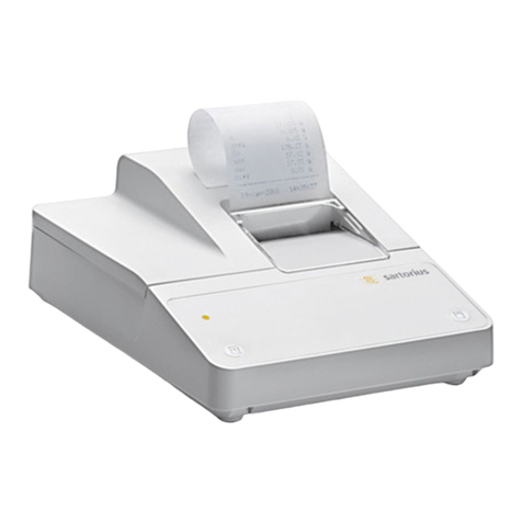
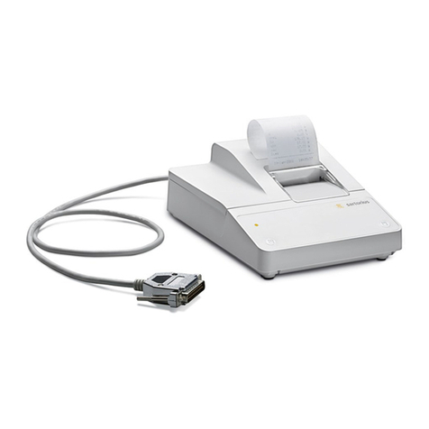
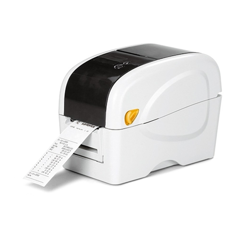
Sartorius YDP30 User manual

Operating Instructions | Betriebsanleitung | Mode d’emploi | Manuale d’uso | Instrucciones de
manejo | Руководство по эксплуатации | 操作说明 | 取扱説明書
Original Operating Instructions | Original-Betriebsanleitung | Mode d’emploi original |
Manuale d’uso originale | Instrucciones de manejo originales | 原始操作说明 | 取扱説明書(オリジナル版)
YDP30|YDP30-NET
Printer | Drucker | Imprimante | Stampante | Impresora | Принтер | 打印机 | プリンター
1000025387

Operating Instructions YDP30 | YDP30-NET 3
Contents
Contents
1 About this Document............................... 5
1.1 Scope......................................... 5
1.2 Target Groups.................................. 5
1.3 Symbols Used .................................. 5
1.3.1 Warnings in Operation Descriptions......... 5
1.3.2 Other Symbols........................... 5
2 Safety Instructions ................................. 5
2.1 Intended Use................................... 5
2.1.1 Modifications to the Device ............... 6
2.1.2 Device Repairs and Maintenance ........... 6
2.2 Personnel Qualification.......................... 6
2.3 Significance of these Instructions ................. 6
2.4 Functionality of the Device....................... 6
2.5 Electrical Equipment ............................ 6
2.5.1
Damage to the Device’s Electrical Equipment
.. 6
2.5.2 Power Supply Unit and Power Supply Cable.. 6
2.6 Conduct in an Emergency........................ 7
2.7 Accessories, Consumables, and Spare Parts.......... 7
3 Device Description ................................. 8
3.1 Device Overview................................ 8
3.2 Connections ................................... 8
3.3 LED Display .................................... 8
3.4 Components for Print Function and
Lock for Top Cover.............................. 9
3.5 Components for Media Feed
and Sensors.................................... 9
4 Installation.......................................10
4.1 Scope of Delivery ..............................10
4.2 Selecting an Installation Site ....................10
4.3 Unpacking....................................10
4.4 Acclimatizing .................................10
5 Getting Started...................................10
5.1 Connecting the Power Supply ...................10
5.2 Connecting the Device to the Testing or Laboratory
Device (YDP30 Only) ...........................11
5.3 Connecting the Device to the Wi-Fi Router or
Corporate Network (YDP30-NET Only) ............11
5.4 Switching the Device On or Off ..................12
5.5 Opening or Closing the Top Cover ................12
5.6 Inserting Media into the Device..................12
5.6.1 Inserting Media into the Media Mount .....12
5.6.2 Inserting Release Paper of Self-adhesive
Media (Peel-off Mode)...................13
5.6.3 Setting the Print Roller to the
Media Thickness ........................13
5.6.4 Completing the Media Insertion...........13
5.7 Inserting the Ink Ribbon ........................14
5.8 Printing Status Information (YDP30-NET Only) .....14
6 System Settings...................................15
6.1 Configure “RS232” Connection (YDP30 Only).......15
7 Cleaning and Maintenance.........................16
7.1 Cleaning Device Surfaces .......................16
7.2 Maintenance Schedule .........................16
7.3 Removing the Ink Ribbon .......................16
7.4 Removing Media from Media Mounts.............17
7.5 Cleaning the Sensors and Interior Components .....17
7.5.1 Cleaning the Print Head..................17
7.5.2 Cleaning the Print Roller or Tear Bar .......17
7.5.3 Cleaning Sensors or the Interior...........17
7.6 Calibrating Sensors and Changing Settings ........18
7.6.1 Check the Configuration Data
of the Device...........................19
7.6.2 Checking Core Dump ....................19
7.7 Re-starting the System .........................19
8 Malfunctions .....................................20
8.1 Device Malfunctions ...........................20
8.2 Malfunctions when Printing.....................20
8.3 Poor Print Quality .............................21
8.4 Re-starting the System .........................21
9 Decommissioning .................................21
9.1 Decommissioning the Device ....................21
10 Transport ........................................22
10.1 Transporting the Device ........................22
11 Storage and Shipping .............................22
11.1 Storing ......................................22
11.2 Returning the Device and Parts ..................22
12 Disposal..........................................22
12.1 Decontaminating the Device ....................22
12.2 Disposing of the Device and Parts ................22
13 Technical Data....................................23
13.1 Dimensions and Weight ........................23
13.2 Ambient Conditions at the Installation Site ........23
13.3 Power Supply . . . . . . . . . . . . . . . . . . . . . . . . . . . . . . . . . 23
13.3.1 Device ................................23
13.3.2 Power Supply Unit ......................23
13.4 Operating Modes and Connection Types...........24
13.5 Connections and Connection Adjustment Options
(YDP30 Only) .................................24
13.6 Printing Process and Print Data ..................24
13.7 Ink Ribbon ...................................25
13.8 Media .......................................25
13.9 Acoustic Emission..............................25
4 Operating Instructions YDP30 | YDP30-NET
Contents
14 Accessories, Consumables, and Spare Parts ..........25
14.1 Accessories ...................................25
14.2 Consumables..................................26
14.3 Spare Parts ...................................26
15 Sartorius Service..................................26
16 Conformity Documents ............................26

Operating Instructions YDP30 | YDP30-NET 5
About this Document
1 About this Document
1.1 Scope
These instructions are part of the device. These instructions
apply to the device in the following versions:
Device Type
YDP30, Standard printer | YDP30-NET,
Network printer
YDP30
1.2 Target Groups
These instructions are written for the following target groups.
The target groups must have acquired the knowledge indicated
below.
Target group Knowledge and qualifications
User The user is familiar with the operation of
the device and the associated work
processes. The user understands the hazards
which may arise when working with the
device and knows how to prevent them.
They have been trained in the operation of
the device.
Operator The operator of the device is responsible for
ensuring compliance with workplace health
and safety regulations. The operator must
ensure that all persons who work with the
device have access to the relevant informa-
tion and are trained in working with the
device.
1.3 Symbols Used
1.3.1 Warnings in Operation Descriptions
WARNING
Denotes a danger with the risk that death or severe injury may
result if it is not avoided.
NOTICE
Denotes a danger with the risk that property damage may
result if it is not avoided.
1.3.2 Other Symbols
t Required action: Describes actions that must be
carried out.
y Result: Describes the result of the actions carried
out.
2 Safety Instructions
2.1 Intended Use
The device is intended to be used to print data from Sartorius
testing or laboratory devices, for example for printouts of
calibration or measurement results from integrity testing
devices or laboratory balances. The device can be used in
laboratories.
Printing is carried out using the “thermo transfer printing” or
“thermo direct printing” printing processes. The device auto-
matically selects the appropriate printing process based on the
inserted media, for example standard paper or thermal paper.
Depending on the model, the device must be set up as either a
standard printer or a network printer and connected to the
testing or laboratory devices (suitability, see Chapter “13.4
Operating Modes and Connection Types”, page 24).
The device is exclusively designed for use in accordance with
these instructions. Any further use beyond this is considered
improper.
If the device is not used properly: The protective systems of the
device may be impaired. This can lead to unforeseeable personal
injury or property damage.
Operating Conditions for the Device
Do not use the device in potentially explosive environments.
Only use the device indoors.
The device may only be used with the equipment and under the
operating conditions described in the Technical Data section of
these instructions.

6 Operating Instructions YDP30 | YDP30-NET
Safety Instructions
2.1.1 Modifications to the Device
If the device is modified, for example by attaching extra
components: The safety of the device may be impaired or the
device compliance may lose its validity.
If you have any queries regarding modifications to the device,
contact Sartorius.
2.1.2 Device Repairs and Maintenance
Device repairs and maintenance may only be carried out by
persons with appropriate specialized knowledge. If the device is
not repaired or maintained by such a person: The safety of the
device may be impaired or the quality marks may lose their
validity.
Even outside the warranty period, we recommend that repairs
be carried out by Sartorius Service or after consulting
Sartorius Service.
Only the maintenance tasks described in these instructions
should be carried out. For maintenance tasks that need to be
carried out by Sartorius Service, contact Sartorius Service.
2.2 Personnel Qualification
If people who do not have sufficient knowledge on the safe
handling of the device carry out work on the device: Those
persons may injure themselves or others nearby.
t Ensure that all individuals working on the device possess the
necessary knowledge and qualifications (description, see
Chapter “1.2 Target Groups”, page 5).
t If a particular qualification is required for the actions
described: Allow these activities to be carried out by the
required target group.
t If no particular qualification is required for the activities
described: Have these tasks carried out by the “user” target
group.
2.3 Significance of these Instructions
Failure to follow the instructions in this manual may have
serious consequences, e.g. danger to individuals.
t Read the instructions carefully and in full.
t Ensure that the information contained in these instructions
is available to all individuals working on the device.
t Retain the instructions.
t If these instructions are lost, request a replacement or
download the latest version from the Sartorius website
(www.sartorius.com).
2.4 Functionality of the Device
A damaged device or worn parts may lead to malfunctions or
cause hazards which are difficult to recognize.
t Only operate the device when it is safe and in perfect
working order.
t Comply with the maintenance intervals (for intervals and
maintenance work, see Chapter “7.2 Maintenance
Schedule”, page 16).
t Allow any damage to be repaired immediately by Sartorius
Service.
2.5 Electrical Equipment
2.5.1 Damage to the Device’s Electrical Equipment
Damage to the device’s electrical equipment, e.g. damaged
insulation, can be life-threatening. There is a danger to life
from contact with live parts.
t If the electrical equipment of the device is defective, cut off
the power supply and contact Sartorius Service.
t Keep live parts away from moisture. Moisture can cause
short-circuits.
2.5.2 Power Supply Unit and Power Supply Cable
Serious injury can result, e.g. from electric shocks, if an
unsuitable/inadequately dimensioned power supply cable or
unsuitable power supply unit is used.
t Only use the original power supply unit and original power
supply cable.
t If the power supply unit or power supply cable needs to be
replaced: Please contact Sartorius Service. Do not repair or
modify the power supply unit or power supply cables.

Operating Instructions YDP30 | YDP30-NET 7
Safety Instructions
2.6 Conduct in an Emergency
If an emergency occurs, e.g., due to the malfunctions of the
device or dangerous situations: People might be injured. The
device must be immediately taken out of operation:
t Disconnect the power supply cable from the power supply
at the installation site.
t Secure the device to prevent it from restarting.
2.7 Accessories, Consumables, and Spare Parts
Unsuitable accessories, consumables, and spare parts can
adversely affect functionality and safety and can have the
following consequences:
− Risk of injury to persons
− Damage to the device
− Device malfunctions
− Device failure
t Only use approved accessories, consumables, and spare parts
supplied by Sartorius.
t Only use accessories, consumables, and spare parts that are
in proper working order.

8 Operating Instructions YDP30 | YDP30-NET
Device Description
3 Device Description
3.1 Device Overview
9
8
7
26 5 34
110 1
Fig.1: YDP30 (front and rear view, example)
Pos. Name Description
1 Top cover
2 On/Off switch
3 Recessed grip
4 Manufacturer's ID
label
Attached to the underside of
the device.
5 Lever Is intended to open the top
cover.
6 Front cover
7 Release paper
opening
For the output of release paper
from self-adhesive media
(peel-off mode).
8 Paper output tray
9 Feed button − Is intended to move
inserted media forward, e.g.
when printing labels.
− Is intended to stop and
resume printing.
− Is intended to select certain
functions, e.g. configura-
tion of the RS232 interface,
calibration of sensors.
10 LED display
3.2 Connections
1 2 3 54
Fig.2: Connections (rear view YDP30, example)
Pos. Name Description
1 Power connection Is intended to connect the
power supply cable.
2 USB USB port
3 RS-232C Serial interface, YDP30 only
Ethernet YDP30-NET only
4 Production
interface
No function
5 Interface for SD
memory card
No function
3.3 LED Display
The LED display denotes the device’s operating status.
Light color and
behavior Description
Green The device is ready for use.
Flashing green The device is receiving data or a print
job has been stopped.
Illuminated yellow/
red
The device is connecting to the Wi-Fi
network or corporate network
(YDP30-NET only).
Illuminated yellow The device is deleting internally
stored data.
Illuminated red The top cover is open.
Flashing red There is a problem, e.g. a paper jam.

Operating Instructions YDP30 | YDP30-NET 9
Device Description
3.4 Components for Print Function and
Lock for Top Cover
1
2
3
5
4
6
7
8
Fig.3: Components for print function and lock for top cover (top cover and ink
ribbon cover open, example)
Pos. Name Description
1 Ink ribbon cover
2 Print head
3 Lock for top cover Keeps the top cover in an
open position. This means
that the top cover
cannot close acciden-
tally.
4 Tear bar
5 Print roller
6 Intake for the ink ribbon
supply spool
7 Adjustment wheel to
wind the ink ribbon
8 Intake for the ink ribbon
take-up spool
3.5 Components for Media Feed
and Sensors
6
5
4
3
1
2
Fig.4: Components for media feed (top cover open, example)
Pos. Name Description
1 Distance sensor
(transmitter)
2 Adjustment wheel for
media feed
Sets the media feed to the
width of the medium.
3 Sensor for black
marking
4 Media feed Keeps the inserted media in
position. Can be set to
different widths.
5 Media mount Holds the spool of the
medium. Consists of 2
mounts, the distance
between which can be
changed. The mounts can be
rotated 180°. This allows the
media mount to be set to 2
media spool sizes.
6 Distance sensor
(receiver)

10 Operating Instructions YDP30 | YDP30-NET
Installation
4 Installation
4.1 Scope of Delivery
Item Quantity Purpose
Device 1
Power supply unit, type
WDS060240
1
Country-specific power
supply cable
1
YDP30 only
Printer connection
cable, type USB
1
Printer connection
cable, type RS232
1
Winding roller 1 Used to wind the
ink ribbon
Operating Instructions 1
4.2 Selecting an Installation Site
Procedure
t Make sure that the following conditions are met at the
installation site:
Condition Features
Ambient
conditions
Suitability tested (see Chapter “13.2
Ambient Conditions at the Installation
Site”, page 23)
Setup surface − Stable, even surface with little
vibration
− Sufficient space for the device.
4.3 Unpacking
Procedure
t Unpack the device.
t Install the device at the intended installation site. The
device must not be dropped or shaken.
t We recommend you keep the original packaging for a safe
and proper return of the device, e.g. for repairs.
4.4 Acclimatizing
When a cold device is brought into a warm environment: The
temperature difference can lead to condensation from
humidity in the device (moisture formation). Moisture in the
device can lead to malfunctions.
Procedure
t Allow the device to acclimatize for approx. 2 hours at the
installation site. The device must be disconnected from the
power supply during that time.
5 Getting Started
5.1 Connecting the Power Supply
Procedure
t WARNING Severe injuries may be caused by using
defective power supply cables! Check the power supply
cable for damage, e.g., cracks in the insulation.
t If required: Please contact Sartorius Service.
t Check whether the country-specific power plug matches
the power connections at the installation site.
t If required: Please contact Sartorius Service.
t Check whether the voltage specifications on the
manufacturer's ID label match those of the power supply at
the installation site.
t If the input voltage is too high: Do not connect the
device to the power supply.
t Please contact Sartorius Service.
t Connect the power supply unit connection cable to the
“Power Supply” connection.
t Connect the power supply cable to the power supply unit
and the power supply at the installation site. The power
outlet must be easy to reach.

Operating Instructions YDP30 | YDP30-NET 11
Getting Started
5.2 Connecting the Device to the Testing or
Laboratory Device (YDP30 Only)
Procedure
t Connect one of the printer connection cables to the
appropriate port on the device and the testing or laboratory
device (for information about ports on the testing or
laboratory device, see the testing or laboratory device’s
operating instructions).
5.3 Connecting the Device to the Wi-Fi
Router or Corporate Network (YDP30-NET
Only)
Multiple testing and laboratory devices can access the device.
Depending on the configuration, the testing or laboratory
devices can access the device via an independent Wi-Fi router
or via a corporate network.
Connection Type Connection of Device and
Testing or Laboratory Device Connection Type Advantage Connection Type
Disadvantage
Access via Wi-Fi router
(independent Wi-Fi
network)
− The device is connected to
the Wi-Fi router via a
network connection cable.
− The testing or laboratory
device is connected to the
Wi-Fi router via Wi-Fi
components.
− Printing can take place via
an independent Wi-Fi
network.
− The device can be used
without considering the
corporate network’s
security guidelines or
network settings.
Only the Wi-Fi print function
of the testing or laboratory
device can be used.
Access via corporate
network
− The device is connected to
the corporate network via a
network connection cable.
− The testing or laboratory
device is connected to the
corporate network via Wi-Fi
components.
− Fewer connection cables are
required.
− No Wi-Fi router is required.
− All Wi-Fi functions of the
testing or laboratory device
can be used.
The device does not support
fixed IP addresses. For this
reason, the Wi-Fi functions of
the testing or laboratory
devices may be restricted, e.g.
only standard authentication
methods are available.
Requirements
− The device and the Wi-Fi router are turned off.
− The testing or laboratory device is enabled and prepared for
Wi-Fi operation (see the testing or laboratory device’s
operating instructions).
Procedure
t Check the suitability of the Wi-Fi router or the corporate
network (for suitability see Chapter “13.4 Operating Modes
and Connection Types”, page 24).
t Connect a network connection cable to the “Ethernet” port
and to the Wi-Fi router or corporate network.

12 Operating Instructions YDP30 | YDP30-NET
Getting Started
5.4 Switching the Device On or Off
Procedure
t To switch the device on: Press the On/Off switch so that it is
in the “I” position.
y When the device is connected to a network: The device
establishes a connection to the Wi-Fi network or corporate
network and retrieves an IP address for the device. This
procedure usually takes 20 seconds.
y The LED display illuminates in the color “yellow”.
y If media and an ink ribbon are inserted into the device: The
device will print an initial printout containing the Sartorius
logo and the current software version.
y The LED display illuminates in the color “green”. The device
is ready for use.
t To switch the device off: Press the On/Off switch so that it
is in the “O” position.
5.5 Opening or Closing the Top Cover
Requirements
The device is switched off.
Procedure
t To open the top cover:
t Pull the levers located
on both sides of the top
cover forwards.
t Open the top cover upward and push it backward until
it stops.
y The top cover lock audibly engages.
t To close the top cover:
t Push sideways against top cover lock. This will unlock
the top cover.
t Push the top cover back down. Both levers should snap
into place.
5.6 Inserting Media into the Device
5.6.1 Inserting Media into the Media Mount
The media spool, e.g. the standard paper roll, must be inserted
between the 2 media mounts. The print side of the media must
be facing up.
Requirements
− The print roller is clean (see Chapter “7.2 Maintenance
Schedule”, page 16).
− The device is switched off.
Procedure
t Check if the media are suitable for the device (suitability,
see Chapter “13.7 Ink Ribbon”, page 25).
t Open the top cover.
t Check if the media mount is
set to the right media spool
size.
t If required: Push the
2 mounts apart and turn
them 180°.
t Push the 2 mounts apart and fix the media spool between
the mounts.
t Push the media over the
media feed, the sensor for
black marking and the print
roller.
t Turn the setting wheel for the media feed so that the media
feed is set to the width of the inserted media.
t Close the top cover.

Operating Instructions YDP30 | YDP30-NET 13
Getting Started
5.6.2 Inserting Release Paper of Self-adhesive Media
(Peel-off Mode)
If the release paper of self-adhesive media has been inserted:
The release paper will automatically be removed during
printing.
Requirements
The device is switched off.
Procedure
t Open the top cover.
t Open the front cover.
t Separate the release paper
from the media and feed it
through the release paper
opening.
t Close the front cover. The
front cover must snap into
place.
t Close the top cover.
5.6.3 Setting the Print Roller to the Media Thickness
321
Fig.5: Lever (set in the position for normal paper, example)
Pos. Name Description
1 Lever For setting the print roller.
2 Position for
normal paper
For setting the print roller to
normal paper thicknesses (for
media thickness, see Chap-
ter “13.8 Media”, page 25).
3 Position for
thick paper
For setting the print roller to the
maximum paper thickness (for
maximum paper thickness, see
Chapter “13.8 Media”,
page 25).
Requirements
The device is switched off.
Procedure
t Open the top cover.
t Fold the front cover downward.
t Push the lever to the desired position, e.g. into the position
for thick paper.
t Fold the front cover upward and let it snap into place.
t Close the top cover.
5.6.4 Completing the Media Insertion
Procedure
t Define the media sensor and calibrate the sensors (see
Chapter “7.6 Calibrating Sensors and Changing Settings”,
page 18).

14 Operating Instructions YDP30 | YDP30-NET
Getting Started
5.7 Inserting the Ink Ribbon
Requirements
− The print head is clean (see Chapter “7.2 Maintenance
Schedule”, page 16).
− The device is switched off.
Procedure
t Open the top cover.
t Open the ink ribbon cover.
t Insert the ink ribbon supply
spool into the intake for
the ink ribbon supply spool
starting with the right side,
then the left side, and then
align it.
t Attach the ink ribbon to the
supplied winding roller, e.g.
with tape.
t Pull the ink ribbon through
the winding roller over the
print head and place first
the right side and then the
left side of the winding
roller on the winding spool
for the ink ribbon and align
it with the recesses.
t Turn the setting wheel
downward to wind the ink
ribbon until the plastic
leader of the ink ribbon is
tightly wound and the
black part of the ink ribbon
is on the print head.
t Close the ink ribbon cover.
t Close the top cover.
5.8 Printing Status Information (YDP30-NET
Only)
The device’s status information is needed for configuring the
testing or laboratory device. The status information should
print within 10 seconds of turning on the device. The printout
should contain the following information:
− Line “IP ADDRESS”: IP address retrieved from the Wi-Fi
network or corporate network by the device.
− Line “HOST NAME”: Host name retrieved from the Wi-Fi
network or corporate network by the device.
If the status information cannot be printed: There is a fault in
the device or Wi-Fi router, or the connection to the corporate
network is interrupted.
Requirements
If a Wi-Fi router is used: The Wi-Fi router is turned on and
ready for use.
Procedure
t If the LED display on the device illuminates in green: Switch
the device off and on again.
t If the status printout has printed and while the LED display
is illuminated in “yellow”: Press the feed button.
y The device will print the device status information. The IP
address of the network printer is specified in the “IP
ADDRESS” line. The host name is specified in the “HOST
NAME” line.
t If the IP address entry is “0.0.0.0”:
t Press the feed button again.
y The status information will be printed again.
y If required: Repeat this procedure up to 5 times.
y If the status information cannot be printed or the IP
address or host name information are still missing:
t Check and adjust the settings for the Wi-Fi server or
corporate network.
t If required: Please contact Sartorius Service.
t Keep the printout of the status information for the
configuration of the testing or laboratory device.

Operating Instructions YDP30 | YDP30-NET 15
System Settings
6 System Settings
6.1 Configure “RS232” Connection (YDP30
Only)
The “RS232” connection can be configured in 2 configuration
options (see Chapter “13.5 Connections and Connection
Adjustment Options (YDP30 Only)”, page 24). The feed button
is used to carry out the configuration.
Requirements
The device is ready for use.
Procedure
t Switch off the device.
t Switch on the device again.
t Once the initial printout has printed: Press the feed button
within the next 3 seconds. This starts the configuration
mode.
y A configuration routine is started, the configuration options
are printed. The following data is printed:
Configuration options Description
SETUP SERIAL PORT:
PRESS KEY: XXXXBdYZZ Shows the adjustable configu-
ration, e.g. 9600BD801. The
configuration can be selected by
pressing the feed button.
WAIT 5s: no change Wait 5 seconds for the next
option to be displayed.
t If you want to select the printed configuration option: Press
the feed button within the next 5 seconds.
y If the configuration option is not selected: The next
configuration option will be printed in the configuration
routine.
y If the configuration option is not selected again: The
configuration routine will be canceled: The notification [no
changes made/EXIT SETUP/print settings] will be printed.
y The device’s configuration data will be printed (see
Chapter “7.6.1 Check the Configuration Data of the Device”,
page 19).

16 Operating Instructions YDP30 | YDP30-NET
Cleaning and Maintenance
7 Cleaning and Maintenance
7.1 Cleaning Device Surfaces
Procedure
t Switch off the device.
t Disconnect the power supply cable from the power supply
at the installation site.
t NOTICE Corrosion or damage to the device due to unsuit-
able cleaning agents!
t Do not use corrosive, chloride-containing or aggressive
cleaning agents.
t Do not use cleaning agents that contain abrasive
ingredients, e.g. scouring agents, steel wool.
t Do not use solvent-based cleaning agents.
t Make sure that cleaning materials, such as cloths, are
only slightly damp. Do not use wet cleaning cloths.
t Wipe the housing with a slightly damp cloth. Use a mild
soapy solution or a suitable cleaning agent for more severe
contaminations.
7.2 Maintenance Schedule
Interval Component Action Chapter,
page
Before media are inserted Print head Remove the ink ribbon. 7.3, 16
Clean the print head. 7.5.1, 17
Print roller Remove the media. 7.4, 17
Clean the print roller. 7.5.2, 17
After media are inserted Sensors Calibrate the sensors. 7.6, 18
Monthly Sensors Remove the media. 7.4, 17
Clean the sensors. 7.5.3, 17
As required Tear bar Remove the media. 7.4, 17
Clean the tear bar. 7.5.2, 17
Interior Remove the media. 7.4, 17
Clean the interior components. 7.6, 18
7.3 Removing the Ink Ribbon
Procedure
t Switch off the device.
t Open the top cover.
t Open the ink ribbon cover.
t Remove the ink ribbon’s paper winding spool from the
winding spool for the ink ribbon first on the left side, then
the right.
t Remove the ink ribbon’s supply spool from the intake for
the ink ribbon’s supply spool first on the left side, then the
right.

Operating Instructions YDP30 | YDP30-NET 17
Cleaning and Maintenance
7.4 Removing Media from Media Mounts
Procedure
t Switch off the device.
t Open the top cover.
t If release paper of self-adhesive media has been inserted:
t Open the front cover.
t Pull the release paper out of the release paper opening.
t Close the front cover.
t Push the 2 mounts of the media feed apart and remove the
media spool.
7.5 Cleaning the Sensors and Interior
Components
7.5.1 Cleaning the Print Head
The print head must not be touched. The print head must be
cleaned with 100% ethanol and a cotton swab or with a print
head cleaning pen.
The print head must not come into contact with medical
alcohol. Medical alcohol can damage the print head.
Requirements
An ink ribbon has not been inserted into the device.
Procedure
t Switch off the device.
t Open the top cover.
t Open the ink ribbon cover.
1
t Use a cotton swab moist-
ened with 100% ethanol or
a print head cleaning pen
to clean the print head (1).
t If the print head accidentally comes into contact with skin:
Clean the print head again.
7.5.2 Cleaning the Print Roller or Tear Bar
The print roller and tear bar must be cleaned with 100%
ethanol and a cotton swab or lint-free cloth.
Requirements
There are no media in the device.
Procedure
t Switch off the device.
t Open the top cover.
t Moisten a cotton swab or lint-free cloth with 100% ethanol.
1
2
t Wipe the print roller (1).
Turn the print roller so that
the entire surface of the
print roller can be cleaned.
t Wipe the tear bar (2).
7.5.3 Cleaning Sensors or the Interior
The sensors and the interior of the device must be cleaned with
an air brush or a vacuum brush.
Requirements
There are no media in the device.
Procedure
t Switch off the device.
t Open the top cover.
2
1
3
t Clean the distance sensor
(receiver) (1), distance
sensor (transmitter) (2), and
sensor for black marking (3)
with an air brush or a
vacuum brush.
t Clean the interior components with an air brush or a
vacuum brush.

18 Operating Instructions YDP30 | YDP30-NET
Cleaning and Maintenance
7.6 Calibrating Sensors and Changing
Settings
The calibration of sensors and setting of the device functions is
done using the feed button while the device is being switched
on. The LED display will flash and change colors throughout the
process.
Color sequence (change every 5 seconds)
Red Yellow Green Green/yellow Red/yellow
The feed button must be held down while the colors change
until the LED display shows the correct color for the desired
function, e.g. “red” to calibrate the sensors.
Available settings LED display
color Description
Define the sensor for black marking as
the media sensor and calibrate
Green/yellow To calibrate labels with black markings
Define the distance sensor as the media
sensor and calibrate
Red/yellow To calibrate labels with gaps
Calibrate sensor for black marking and
distance sensor
Red For the initial calibration when using individual labels. The
calibration is saved to protected memory.
Calibrate sensor for black marking and
distance sensor, perform self-test, and
print in core dump mode
Yellow The following functions are run one after the other:
− The sensitivity of the sensors is set. During this process, the
device measures the length of the labels.
− The device performs a self-test and prints the configuration
data (see Chapter “7.6.1 Check the Configuration Data of the
Device”, page 19).
− The device prints a core dump (see Chapter “7.6.2 Checking
Core Dump”, page 19).
Restore device to factory settings Green If the device has been calibrated to print individual labels: To
change calibration to print on continuous paper
The following functions are conducted:
− The internal memory (DRAM) is deleted.
− The device is reset to factory settings.
Requirements
− The ink ribbon and media have been inserted in the device.
− If a self-test needs to be performed: The inserted media
have the required minimum width (see Chapter “12.1
Decontaminating the Device”, page 22).
Procedure
t Switch off the device.
t Press and hold the feed button while switching on the
device.
t Hold the feed button down until the LED display shows the
correct color for the desired function, e.g. “red” to calibrate
the sensors.
t When the LED display shows the correct color: Release the
feed button.

Operating Instructions YDP30 | YDP30-NET 19
Cleaning and Maintenance
y The device will perform the functions, e.g. calibration of
sensors.
y Depending on the device function, media will come out of
the paper output tray with or without print function.
7.6.1 Check the Configuration Data of the Device
If a self-test has been performed or settings have been
changed: The device’s configuration data will be printed. The
printout contains the following information:
Configuration data Description
YDP30 | YDP30-NET Version: X.XX. XX Name and firmware version on the main board
SERIAL NO.: No entry
MILAGE (m): XXX Already printed (in meters)
CHECKSUM: XXXXXXXX Checksum of the main board firmware
SERIAL PORT: XXXX, X , X , X Configuration of the “RS232” connection
CODE PAGE: XXX Code page
COUNTRY CODE: XXX Country code
SPEED: X INCH Print speed in inch/second
DENSITY: X. X Print density
SIZE: X.XX , X.XX Label size: Width, height
GAP: X.XX , X.XX Gap size (vertical gap, offset)
TRANSPARENCE: X Sensor sensitivity
[FILE LIST:] File management information, e.g. number of files in the internal memory
[Sample] Print head test sample
Procedure
t Check the information on the printout.
t If required: Change the settings.
7.6.2 Checking Core Dump
In the core dump, characters are listed in two columns. The
received characters are listed in the left column. The hexadeci-
mal values of the characters are listed in the right column.
Procedure
t Check the information on the printout.
t If required: Change the settings.
7.7 Re-starting the System
Procedure
t Commission the device (see Chapter “5 Getting Started”,
page 10).

20 Operating Instructions YDP30 | YDP30-NET
Malfunctions
8 Malfunctions
8.1 Device Malfunctions
Malfunction Cause Solution Chapter, page
The LED display is
inactive.
The device is switched off. Switch on the device. 5.4, 12
The device is not connected to the
power supply at the installation
site.
Connect the device to the power supply
at the installation site.
5.1, 10
8.2 Malfunctions when Printing
Malfunction Cause Solution Chapter, page
The device does not
print.
A print job has been stopped. The
LED display flashes green.
Press the feed button. This will resume
the print job.
No media have been inserted. The
LED display flashes red.
Insert the media. 5.6.1, 12
The inserted media have been used
up.
Remove the media spool. 7.4, 17
Insert the media. 5.6, 12
Press the feed button. This will resume
the print job.
The ink ribbon has been inserted
incorrectly.
Remove the ink ribbon. 7.3, 16
Insert the ink ribbon. 5.7, 14
The device does not
print (only when used
as standard printer).
The device is not correctly
connected to the testing or
laboratory device.
Check the connection. 5.2, 11
The RS232 connection cable is not
correctly assigned.
Use the supplied printer connection
cable, type RS232.
If the printer connection cable is
missing: Please contact Sartorius
Service.
The settings for the serial interface
between the device and the
testing or laboratory device differ.
Change the configuration for the
“RS232” connection.
6.1, 15
The device does not
print (only when used
as network printer).
The device received multiple print
jobs simultaneously and has only
printed the first print job.
Restart the missing print job.
The device is not correctly
connected to the testing or
laboratory device.
Print the status information. 5.8, 14
Check if the device is correctly
configured on the testing or laboratory
device (see the testing or laboratory
device’s operating instructions).
The media shift during
printing.
The printer settings are incorrect. Change the media sensor settings. 7.6, 18
Reset the device to factory settings. 7.6, 18
Calibrate the sensors. 7.6, 18
Other manuals for YDP30
1
This manual suits for next models
1
Table of contents
Languages:
Other Sartorius Printer manuals

Sartorius
Sartorius YDP30 User manual

Sartorius
Sartorius YDP40 User manual

Sartorius
Sartorius YDP20-0CE User manual

Sartorius
Sartorius YDP10-0CE User manual

Sartorius
Sartorius YPD20-OCE User manual

Sartorius
Sartorius YDP 03-0CE User manual

Sartorius
Sartorius YDP 04 User manual

Sartorius
Sartorius YDP10BT-0CE User manual

Sartorius
Sartorius YDP40 User manual