SASFORKS Male Master User manual

OPERATOR MANUAL
AND SERVICE GUIDE
FOR SAS™ MALE
MASTER / QUICK
COUPLER SYSTEM
O:\PROCEDURES\Forks\OPERATOR MANUALS\Male Master QC Operator Manual\00-Cover.doc
www.sasforks.com © 2014, 2004, 1987 S.A.S. of Luxemburg, Ltd. 1-877-SAS-FORK

TO THE OWNERS, MANAGERS, AND OPERATORS OF LOADERS AND FORK
LIFTS EQUIPPED WITH SAS FORKS™
Safety is the most important issue in the workplace. Observing safety guidelines, equipment capacities and
using common sense will provide a work environment that is safe and efficient for employees, management
and customers. This operator manual has been assembled and sent to help you and your operators to move
products quickly and safely. It is important that you and your operators read and understand the information
included here in.
A key element in safely moving vehicles with SAS FORKS™ is that all necessary people are trained,
including:
•Machine Operators.
•Personnel working in the area of the operation of a machine equipped with SAS FORKS™
•Other individuals that Owners or Management of your company feel need to be trained.
Prior to using SAS FORKS™, ensure that all personnel that will use and/or work in the area of the
SAS FORKS™ read the following:
•Machine Manufacturer’s Operator Manual
•Operator Manual for Machines Equipped with SAS FORKS™ (This Manual)
•Identification Plate on the SAS FORKS™
We recommend that Management complete the following items prior to using SAS FORKS™ :
•Conduct a meeting with all personnel and an Experienced Machine Operator to review and discuss
safety, capacities, limitations, and proper operational procedures.
•Obtain a signature from each person acknowledging such training & file in their personnel file.
Daily workplace and operational safety is the responsibility of the Owners, Managers, and Operators.
•Knowledgeable & routine supervisory duties to ensure that safe operating practices are followed.
•Regular maintenance and inspection of the equipment, with documentation of such.
•Periodic meetings, reviewing operating guidelines, signed by all of the attending personnel.
The proceeding outline, and the following information laid out in this Operator Manual for SAS FORKS™
is intended to be a guide only, and is not meant to encompass all issues that may need to be addressed for
your particular type of business operation.
If you should encounter any additional information that would be helpful to us, or others, please contact us.
Thank you for your business, Phone: 1-877-SAS-FORK
Phone: 1-877-727-3675
PAUL SECKER, President Phone: 1-920-845-2307
S.A.S. OF LUXEMBURG, LTD. Fax: 1-920-845-2309
E1039 Hwy 54 •PO Box 260 E-Mail: sales@sasforks.com
LUXEMBURG, WI 54217 Web site: www.sasforks.com
O:\PROCEDURES\Forks\OPERATOR MANUALS\Male Master QC Operator Manual\01-Fork Management.doc
www.sasforks.com
© 2014, 2004, 1987 S.A.S. of Luxemburg, Ltd. 1-877-SAS-FORK
Page 1

INITIAL SHIPPING RECEIPT OF ITEM
Inspect for any shipping damage IMMEDIATELY upon receipt from the freight company.
If any damage is found:
•Prior to signing the shipping receipt document, write in the document the extent and description of the
damage.
•Call our office at 920-845-2307 and report the damage.
•Email photographs of the damage to: inspection @sasforks.com
Obtain packing slip and parts list, check to make sure you received all parts shown on packing slip.
If you have any questions, please contact us at 920-845-2307.
Typically SAS™ Quick Couplers are shipped in this manner:
SAS™ Male Master Quick Coupler on a pallet (See photo at right)
OPTIONAL ITEMS AVAILABLE FOR SPECIAL ORDER:
•Installation pins
•Coupler Ribs to adapt your current bucket or attachments to interchange with the
SAS™ Quick Coupler (see photo at right)
•Pressure limiting valves (to keep the PSI under 2,500)
•Auxiliary 3rd Spool Pump Kit(s):
oElectric Hydraulic pump kit (24 volt) with remote pendent switch
MOUNTING INSTALLATION GUIDELINES:
•It is recommended that installation be done by a Heavy Equipment Service
Technician, who is aware of the hazards associated with handling heavy parts.
•Make a clear work area and eliminate any trip hazards.
•The machine should be parked on firm level ground with the engine off and the parking brake set.
•Follow the machine manufacturer’s instructions to properly depressurize the hydraulic system.
•Watch for pinch points.
•Remove any existing pined on attachment on the machine where the new quick coupler will be attached
•Grease pins and pin sleeves.
•Align pin holes, sleeves and insert pins. Properly secure pins in place.
PINCH POINTS
When Male Master is in use avoid possible pinch points to prevent serious injury. Keep hands and loose clothing
clear at all times.
O:\PROCEDURES\Forks\OPERATOR MANUALS\Male Master QC Operator Manual\02-Initial Shipping Receipt.doc
www.sasforks.com
© 2014, 2004, 1987 S.A.S. of Luxemburg, Ltd. 1-877-SAS-FORK
Page 2

HYDRAULIC PRESSURE REQUIREMENTS
SAS Male Master Hydraulic Quick Coupler operates at a maximum of 5,000 PSI. Most machines operate below this
pressure it is recommended that machine pressure is checked and set prior to operating unit. Failure to do so can cause
catastrophic failure of cylinder, fittings and/or hoses.
Operation of hydraulic Quick Coupler can be obtained through several options.
Option #1 Electric Pump with remote pendent button
SAS stand alone 24 volt hydraulic pump with pendent (push button) control unit. This pump is electrically
controlled and can be mounted anywhere on the loader with the control unit installed in the cab. All hoses, fittings,
wires, wire connectors and pump with pendent control are included in this kit. No pressure reducing valves are
required. Pendent control shown below.
See following page for installation diagram
Option #2 Tap into bucket roll back hydraulics
Bucket roll back cut out solenoid. This kit T’s into the bucket roll back circuit of the loader. It includes all
fittings, bulk 60’of 3/8” hose, wire, wire connectors, actuator switch, lock out solenoid and reducing valve.
Option #3 (Units with factory installed Quick Coupler hydraulics factory installed)
This kit contains 60’ bulk 3/8” hose and fittings.
O:\PROCEDURES\Forks\OPERATOR MANUALS\Male Master QC Operator Manual\03-Hydraulic Pressure Requirements.doc
www.sasforks.com
© 2014, 2004, 1987 S.A.S. of Luxemburg, Ltd. 1-877-SAS-FORK
Page 3

Sales on “Sassvr02”/ADMINISTRATION/A-Product Sheets/Product Brochures/24V PUMP LIT INSTRUCTIONS
PENDENT
SWITCH
WHITE TO SMALL
UPPER TERMINAL
ON MOTOR SOLENOID
RED TO #1 GREY
WIRE ON RIGHT
SOLENOID VALVE
GREEN TO #2 GREY
WIRE ON LEFT
SOLENOID VALVE GROUND CABLE
TO BATTERY ( - )
POWER CABLE
TO BATTERY ( + )
FUSE
HOLDER
POWER INTO
MOTOR
PURPLE GROUND WIRE
TO MOTOR HOUSING
SOLENOID
VALVE #1
SOLENOID
VALVE #2
FILL
PLUG
TANK
24V MOTOR
SOLENOID
24V MOTOR
SOLENOID
OVERALL SIZE:
8” TALL x 6” DEEP x 17” LONG
TANK/PUMP MOUNT POSITION:
DUE TO PICKUP TUBE INSIDE TANK,
UNIT MUST BE MOUNTED ON FLAT/
LEVEL SURFACE.
FOR EXAMPLE:
ON
OFF
OPERATION:
ON: PRESS “UP” BUTTON TO LOCK PINS
OFF: PRESS “DN” BUTTON TO UNLOCK PINS ATTACH
HOSE TO
COUPLER
ATTACH
HOSE TO
COUPLER
STAMPED
“C2” STAMPED
“C1”
“C2” HOSE
TO PUMP
“C1” HOSE
TO PUMP
BLACK TO LARGE
“HOT” TERMINAL
ON MOTOR SOLENOID
24V PUMP KIT
WIRING INSTRUCTIONS
S.A.S. of Luxemburg, Ltd. Center Drive Hwy 54
PO Box 260, Luxemburg, WI 54217 USA
Phone: 920-845-2198 1-877-SAS-FORK Fax: 920-845-2309
Email: sales@sasforks.com Web: www.sasforks.com
© 2010 S.A.S. of Luxemburg, Ltd.

DAILY PRE-OPERATION INSPECTION AND GREASING
Secure the machine:
•Park the equipment on firm level ground
•Lower the forks to the ground. Position forks flat on the ground
•Lower the grapple if equipped to the lowest resting position
•Set the parking brake and/or block the wheel s on the equipment
•Turn off the engine
•Move the hydraulic control levers for the lift, tilt and grapple back and forth to relieve any built up
pressure in the system
Put on appropriate Personal Protective Equipment (PPE):
•At a minimum, wear safety glasses. Your worksite may require additional PPE such as steel toe shoes,
hard hat, leather gloves, etc. Be sure to observe your workplace rules.
Observe these safety precautions:
•Never attempt to grease the coupler mounting pins when the machine is running, you could be crushed in
the operating linkage
•Never attempt to grease the coupler mounting pins when the forks are lifted up off the ground, you could
be crushed if the forks would drop to the ground.
Conduct a thorough pre-operation inspection of the forks while greasing the pins and joints.
•See separate suggested pre-operation inspection list in this manual.
Proper Greasing:
•Grease all pins and rotating points daily, prior to use. To be sure grease is being fully applied into the
joint, grease should be pumped into the grease zerk until it squirts out around the pin and rotating point.
Operation
Locking pin must be sure to be fully locked / engaged so the attachment doesn’t fall off.
Male Master Quick Coupler PIN recessed, unlocked position. Male Master Quick Coupler PIN fully engaged in attachment
O:\PROCEDURES\Forks\OPERATOR MANUALS\Male Master QC Operator Manual\05-Daily Pre-Operation Inspection and Greasing.doc
www.sasforks.com
© 2014, 2004, 1987 S.A.S. of Luxemburg, Ltd. 1-877-SAS-FORK
Page 5

O:\PROCEDURES\Forks\OPERATOR MANUALS\Male Master QC Operator
Manual\06-Wheel Loader Daily Inspection Sheet 06-06.doc
www.sasforks.com
Page 6

GENERAL FORKS OPERATING PRECAUTIONS
WHEEL LOADERS: REMOVE “LOCK POSITION”, “DETENT’,& “AUTOMATIC DUMP”
Remove the lock position, detent control, and auto dump features on the up and down levers. These features were originally
intended for wheel loaders moving gravel in buckets and dumping it into trucks. These controls, if left operable on your
machine, could cause accidents by raising or lowering the load instantly. These are not desirable features with using forks to
handle loads.
LIFT CAPACITY
•Observe the most restrictive weight capacity provided by the equipment manufacturer, in the
manufacturer’s operator manual, on the cab id plate, and on the identification plate of your SAS
FORKS™. Attempting to lift loads in excess of the lowest rated capacity will result in an unsafe
condition. Damage may occur to the equipment, forks, or even cause loss of steering control, and tip over
the loader/forklift.
LIFT HEIGHTS
•Observe the most restrictive lift height provided by the equipment manufacturer, posted on the original cab
plate, in the manufacturer’s operator manual, and/or on the forks identification plate.
•Lift height limitations are in place to protect the operator, and to ensure stability of the equipment. In
wheel loaders equipped with ‘dirt digger linkages’, the load may suddenly dump without any control or
warning, if the maximum lift height is exceeded. (Some machine’s max. lift height are 8’)
•Never raise the forks to the maximum lifting height and point the fork blades in the air. You could hit a
power line and be electrocuted.
TURNING WHILE CARRYING A LOAD
•During transport of a load, keep the load close to the ground, (ie: 2 feet or less) On articulated equipment,
such as a wheel loader, it is not safe to turn (articulate) if the load is more than 2 feet above the ground.
•The best way to lift loads at heights above 2 feet, is to position your equipment, with the wheels, either
straight in line, or turned less than 5°. Then lift, and place the load without turning the machine.
•Never articulate a wheel loader more than 5 degrees right or left with the load at a height of more than 2
feet above ground. The wheel loader could tip over.
WARNING SOUNDS
•Sound horn when approaching blind areas, like around corners of buildings or garage. This is necessary to
alert other people who may not be able to see that you are approaching.
•Your wheel loader/forklift must be fitted with a safety beep to sound when backing (reverse) to warn
people. If safety beeper is inoperable, it must be immediately fixed prior to further use of the loader/forklift.
PEOPLE / PEDESTRIANS / WORKERS
•At all times you must be aware of the location of all people in the vicinity of your equipment and the load
you are transporting. You are responsible to maintain a safe operating distance from them. A minimum
recommended distance that all people must stay clear is 30 feet.
•
Never lift a load and let someone walk or work under the forks. Anything could happen and the load may
drop crushing anyone under the load, causing severe injury or death.
GENERAL USE
•
Never put the tips of the forks on the ground and raise the front wheels of the forklift/wheel loader off the
ground. The forks may break and/or the forklift/wheel loader may tip over.
•
Never operate equipment without correct tire pressure in all tires. A soft tire could cause the unit to tip over
•Always park equipment with the forks lowered flat to ground, & grapple lowered to resting closed position.
O:\PROCEDURES\Forks\OPERATOR MANUALS\Male Master QC Operator Manual\07-General Operating Precautions.doc
www.sasforks.com
© 1987-2006 S.A.S. of Luxemburg, Ltd. 1-877-SAS-FORK
Page 7

SAFETY
Buyer accepts the responsibility to (1) Ensure that all personnel that will use and/or work in the area of the purchased product will read
the safety ID plate and the Operator Manual For Machines Equipped With SAS FORKS™ and the Machine Manufacturer’s Operators
Manual, prior to use; and (2) Ensure that all personnel follow the safety guidelines outlined on these materials.
S.A.S. OF LUXEMBURG, LTD. IS NOT RESPONSIBLE FOR SAFETY IN THE FIELD.
GOALS OF THE S.A.S. OF LUXEMBURG, LTD. LIMITED WARRANTY PROCEDURE
•ASSURE MINIMUM CUSTOMER DOWNTIME by resolving the problem correctly on a timely basis.
•ASSURE END-USER CONFIDENCE while maintaining an equitable Warranty expense for both your company and SAS.
•PRODUCT IMPROVEMENT. We have an engineering staff ready to assist you. Call us at 1-877-SAS-FORK (1-877-727-3675)
Please call SAS before attempting any repair, modification, or questionable job applications.
LIMITED WARRANTY FOR SAS FORKS™
For products that S.A.S. of Luxemburg, Ltd. (SAS) manufactures, SAS warrants that such products conform to all specifications for
materials and workmanship for the period of time indicated below, after delivery, when used in compliance with the SAS FORKS™
Operator Manual. DEFECTS IN WORKMANSHIP & MATERIAL SPECIFICATIONS
PRODUCT TYPE LIMITED WARRANTY PERIOD ITEM COVERED
STANDARD HEAVY DUTY 15’ SAS FORKS™ 1 YEARS FROM ORIGINAL SHIP DATE CARRAIGE UNIT
STANDARD HEAVY DUTY 15’ BLADES 3 YEARS FROM ORIGINAL SHIP DATE FORK BLADE
ALL OTHER SAS FORKS™ (listed below) 1 YEAR FROM ORIGINAL SHIP DATE CARRAIGE UNIT
MEDIUM DUTY SHORT SAS FORKS™, HEAVY DUTY SHORT CRUSHING SAS FORKS™, THE CLAW™, SAS RAKE FORK,
MEDIUM DUTY LONG SAS FORKS™, EXTRA HEAVY DUTY LONG SAS FORKS™ , LIGHT DUTY LONG TUBULAR.
BLADES FOR ABOVE LISTED SAS FORKS™ 1 YEAR FROM ORIGINAL SHIP DATE FORK BLADE
FORGED FORKS 1 YEAR FROM ORIGINAL SHIP DATE CARRIAGE UNIT
FORGED FORK BLADES None, Not a SAS manufactured component. NA
SAS FORKS™ BUMPERS None NA
SKID PLATES None NA
OTHER PRODUCTS NOT LISTED None, unless specified on face of original invoice NA
SAS does not warrant the products that it does not manufacture. Rather, all warranties, if any, for these products are supplied by the
manufacture. SELLER EXPRESSLY DISCLAIMS ALL OTHER WARRANTIES, WHETHER EXPRESSED OR IMPLIED,
INCLUDING THE IMPLIED WARRANTIES OF MERCHANTABILITY AND FITNESS FOR A PARTICULAR PURPOSE.
CALL FOR WARRANTY CONSIDERATION: To be considered for warranty repairs or replacement buyer must notify SAS of any
warranty claim within 10 days after such claim arises, and prior to expiration of the warranty period and prior to the performance of any
repairs being done, otherwise buyer waives all rights to such claim.
•Obtain the serial number off the forks and call SAS at 1-877-SAS-FORK. Clearly describe the problem and the operation that was
taking place when it occurred.
•Buyer is to return defective assembly, freight prepaid, or photographic evidence clearly showing the problem area and details of failure
to SAS for review. When necessary, a factory representative may evaluate the problem in the field.
WHAT SAS WILL DO: SAS will examine the defective product, and the details of the failure. If SAS determines that the failure of
materials or workmanship was proven to be within the terms of this limited warranty, SAS will, at it’s option, repair or replace, FOB the
factory, in Luxemburg, WI, USA, the defective product. If the product cannot be returned to the factory, SAS may approve field repair
of defective product. SAS will approve an appropriate amount of hours and cost for the repair before authorizing repairs to begin. No
provisions will be made for incidental damages, mileage, travel time, overtime, downtime, or special freight charges.
O:\PROCEDURES\Forks\OPERATOR MANUALS\Male Master QC Operator Manual\08-Safety Warranty pg1.doc
www.sasforks.com
© 2004, 1987 S.A.S. of Luxemburg, Ltd. 1-877-SAS-FORK
Page 8

FORK BLADE LIMITED WARRANTY
•BENT FORK BLADES are a condition of operation error and are NOT a warranted condition. If you do bend a blade, call
1-877-SAS-FORK and a factory representative will assist you in the procedure for straightening the bent blade. The blades, under most
circumstances, can be straightened.
•BROKEN/CRACKED FORK BLADES must meet the following specifications to qualify for a broken blade replacement:
1) The tips of the blade must measure at least 90% of the original thickness at the originally designed length.
•The STANDARD 15’ HEAVY DUTY FORK BLADES are designed and shipped from the factory at one and one-half
(1 ½”) inches thick and one hundred and ninety two (192”) inches long.
•ALL OTHER BLADES ARE CUSTOM DESIGNED; Consult SAS for original fork blade design specifications.
2) The blades must not have been welded or ground in any manner other than for welding of factory approved skid pads.
3) The blades must not have an upward deflection of more than 1” per 10’ as measured from the tip. *
4) The blades must not be cracked from the bottom, or the crack must not originate from the bottom.*
*Both of the above conditions are caused from repeated down pressure. This is not a warrantable condition. See page 5 and 8
5) Refer to the ‘conditions that will void your warranty’
If the blade(s) break and the blades meet these conditions, the factory will ship you freight collect a new replacement blade at no charge.
BLADE WEAR
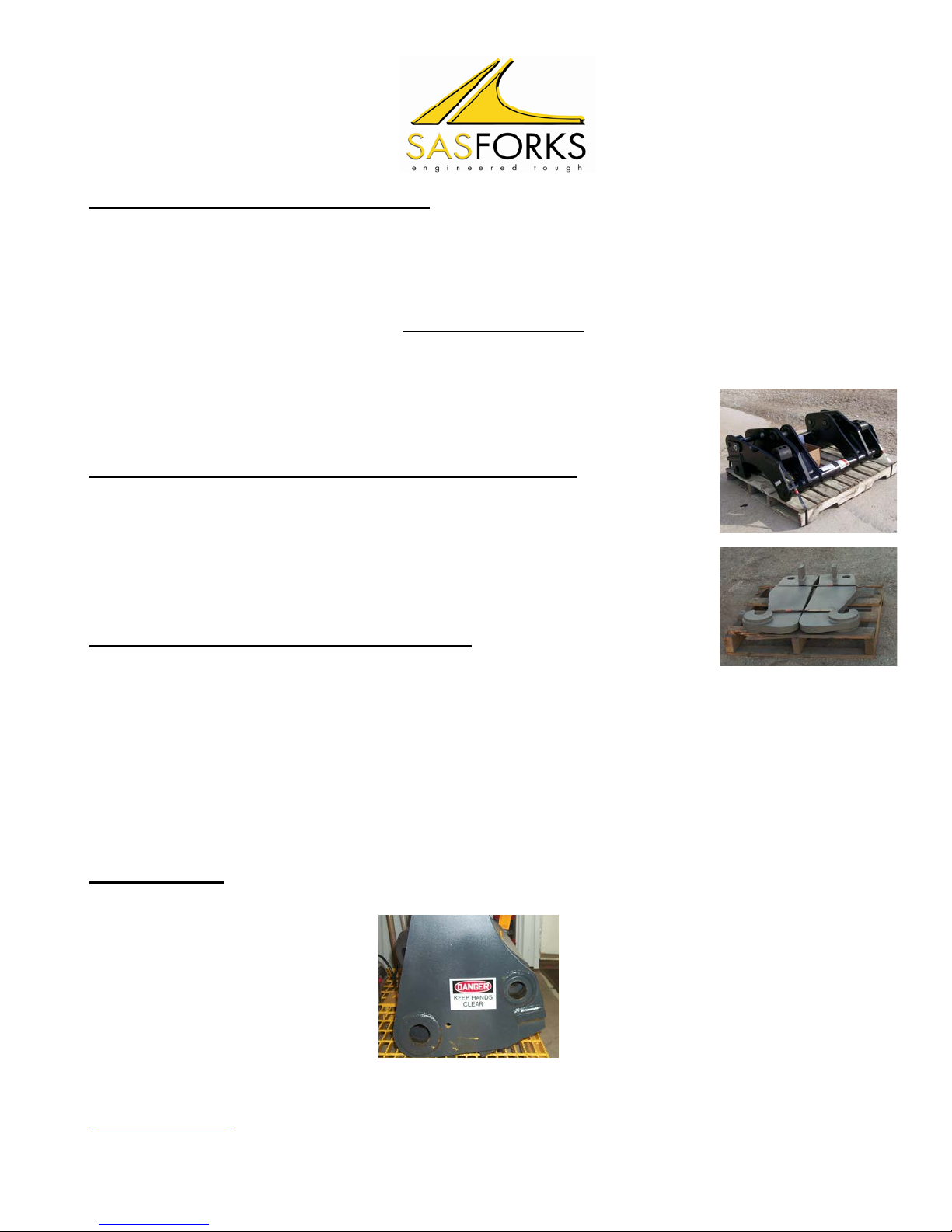
CARRIAGE UNIT LIMITED WARRANTY
•UPPER CARRAIGE UNIT FIT AND CONSTRUCTION: We guarantee our SAS FORKS™ to fit your machine as designed to match
the specifications you provided.
This is warranted against cracks in material, weldments, and factory machined areas.
•WEAR OF BASE PLATE LOWER CARRAIGE, which is structural material, voids the warranty. This is caused from not maintaining
skid plates under the carriage. See page 6.
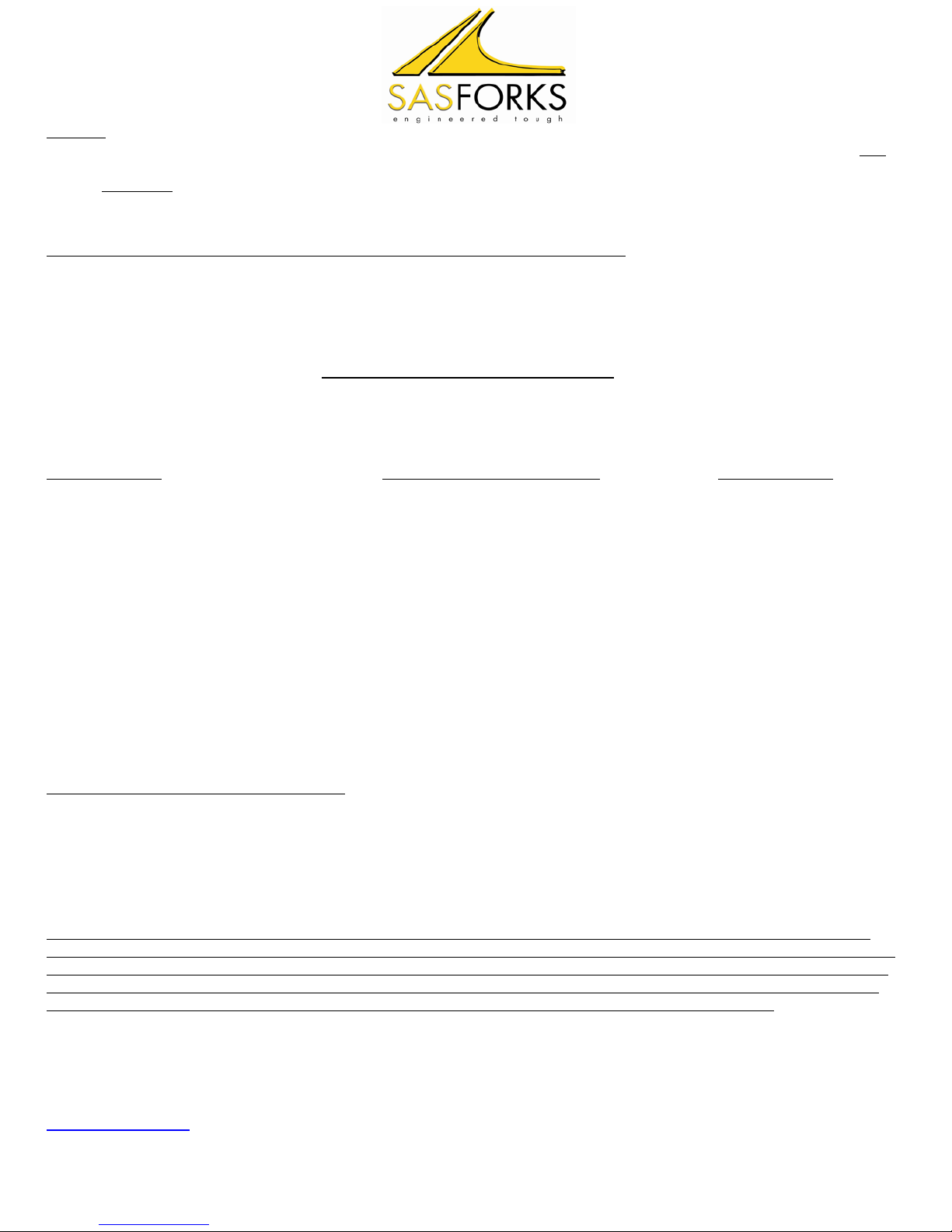
•BROKEN/CRACKED LOWER CARRAIGE:
Cracking or breaking of the carriage unit from the bottom voids the warranty. This is caused from improper operation. Usually caused
by repeated down pressure and wheelies. This is not a warrantable condition. See pages 5 and 8.
CONDITIONS THAT WILL VOID YOUR WARRANTY: Failures, which in our determination were the result of:
•Improper installation.
•Misapplication - See SAS FORKS™ Operator Manual.
•Misuse or Improper operation – See SAS FORKS™ Operator Manual.
•Exceeding the weight and/or lift limitation posted on the Identification Plate attached the SAS FORKS™.
•Negligence or Failure to perform routine inspection and/or maintenance as outlined in the SAS FORKS™ Operator Manual.
•Unauthorized modification, welding, burning, grinding, installation of non-factory skid plates, etc. (other than specifically allowed
in the SAS FORKS™ Operator Manual or as provided in a written authorization directly from SAS factory Engineers.).
•Continued use after a malfunction of the hydraulic system in the forklift or loader.
•Accidental damage.
LIMITED WARRANTY REMEDIES: Buyer must notify SAS of any warranty claim within 10 days after such claim arises; otherwise
buyer waves all rights to such claim. Unless agreed otherwise in writing. Buyer’s sole remedy for breach of warranty is, at seller’s
option, the repair of the defect, or the providing of a replacement part F.O.B. seller’s office. Seller will not be responsible for costs of
dismantling or reassembling the product. Further, seller will not be liable for any direct, indirect, consequential, incidental, or special
damages arising out of a breach of warranty. These remedies are exclusive, and all other warranty remedies are excluded.
PROPRIETARY RIGHTS: All designs and other proprietary rights provided by SAS to Buyer are to remain the property of SAS, and
Buyer shall honor all proprietary legends. Buyer agrees not to copy the design of S.A.S.™ Forks.
LIMITATION OF LIABILITY: The seller’s price is based on the enforceability of this limitation of liability, and the buyer understands
that the price would be substantially higher without this limitation. Seller shall have no liability to buyer for lost profits or for special,
consequential, exemplary, or incidental damages of any kind, whether arising in contract, tort, product-liability, or otherwise, even if
advised of the potential damages in advance.
•In no event shall seller be liable to buyer for any damages whatsoever in excess of the contract price.
•In the event that any warranty or warranty remedy fails of its essential purpose, or is held to be invalid or unenforceable for any reason,
in consideration of the other provisions of this agreement, the parties understand and agree that all limitations of liability under this
provision will nevertheless remain in effect.
SEVERABILITY: Any legally unenforceable provision may be severed from this agreement, and the remaining terms and conditions
will be enforced as a whole.
O:\PROCEDURES\Forks\OPERATOR MANUALS\Male Master QC Operator Manual\09-Safety Warranty pg2.doc
www.sasforks.com © 2004, 1987 S.A.S. of Luxemburg, Ltd. 1-877-SAS-FORK
Page 9

Page 10

Page 12
M-3551
Ref.
No. Part No.
Description
No.
Req.
1 2 3
4 5 6
7 8 9
10 11
12 13
14 15
16 17
18 19
20 21
22 23
24 25
26 27
28
03404
01418
03345
01076
01412
03734
03351
03735
03490
03453
03690
03691
03369
03487
01418
03394
07132
07279
00678
07301
00455
00707
07158
00678
07301
07193
01349
17071
03427
03335
03467
03343
08111
08112
08120
02318
07625
07781
07737
07738
BOX ASSEMBLY, Push Button • STRAIN RELIEF,
(Plastic) • SWITCH, Push Button, 3-Terminal
CLAMP, Cable TERMINAL, Butt Connector Cord,
Harness, 72" 16-4, valve grounded (push button)
Cord, Harness, 72" 16-4, switches grounded (push
button) Cord, Harness, 72" 16-4, valve grounded
(toggle & rocker) Cord, Harness, 72" 16-4,
switches grounded (toggle & rocker) BOX
ASSEMBLY, Push Button (weatherproof) • PARTS
KIT, Gasket, (weatherproof) • PARTS KIT, Strain
Relief, (weatherproof) • SWITCH, Push Button,
3-Terminal (weatherproof) BOX ASSEMBLY,
(Toggle Switch) • STRAIN RELIEF, (plastic) •
SWITCH, Toggle VALVE, 4 Way -2 Position, (12V)
VALVE, 4 Way -2 Position, (24V) • COIL, 10 VDC,
grounded • COIL, 18 VDC, grounded •
CARTRIDGE, 4 Way -2 Position VALVE, 2 Way -
2 Position, 12 VDC, grounded VALVE, 2 Way - 2
Position, 24 VDC, grounded • COIL, 10 VDC,
grounded • COIL, 18 VDC, grounded •
CARTRIDGE, 2 Way 2 Position, N.C. STRAP,
Motor-Solenoid Connecting SCREW, Pan Head
Machine 10-32 x 5/16" SWITCH, Solenoid, 12
VDC, 3-post grounded to canSWITCH, Solenoid,
12 VDC 4-post isolated ground SWITCH,
Solenoid, 24 VDC, 3 post, grounded to can
SWITCH, Solenoid, 24 VDC, 3 post, insulated
ground MOTOR, Electric, 12 VDC MOTOR,
Electric, 12 VDC MOTOR, Electric, 24 VDC •
BEARING, Base, motor • NUT, Hex 5/16-24 •
WASHER, Lock 5/16" • WASHER, Star 1/4" •
SCREW, Hex Head Cap 1/4-20 x 6-1/2"
1 1 2
1 2 1
1 1 1
1 1 1
2 1 1
1 1 1
11 1
1 1 1
1 1 1
2 1 1
1 1 1
1 1 1
1 1 2
2
Ref.
No.
Part No. Description No.
Req.
29 30
31 32
33 34
35 36
37 38
39 40
41 42
43 44
45 46
47 48
49 50
51 52
FOR FURTHER BREAKDOWN OF MOTOR, SEE MOTOR
SECTION 12379 BASE ASSEMBLY 00120 • O-RING, Industrial
(1/2" x 5/8" x 1/16") 02352 • O-RING, Industrial (3-5/8" x 3-7/8" x
1/8") 07526 • PARTS KIT, Valve Assembly, poppet/ball check
03276 • PLUG 02159 • SEAL 03274 • PLUG 01723-x.xx •
VALVE, Press, comp. orifice (specify gpm for x.xx) 07527 •
PARTS KIT, Relief Valve 03766 • PARTS KIT, Relief Valve
K12171-150 PUMP ASSEMBLY, Modular K12171-200 PUMP
ASSEMBLY, Modular K12171-250 PUMP ASSEMBLY, Modular
K12171-270 PUMP ASSEMBLY, Modular K12171-330 PUMP
ASSEMBLY, Modular K12171-380 PUMP ASSEMBLY, Modular
K12171-510 PUMP ASSEMBLY, Modular 07819 • SCREW,
1/4-20 x 2 3/4 Socket Head Cap (For Pump Assembly -150 &
-200) 07818 • SCREW, 1/4-20 x 3 Socket Head Cap (For Pump
Assembly -250, -270, -330, -380) 07837 • SCREW, 1/4-20 x 3
1/4 Socket Head Cap (For Pump Assembly -510) 06102
RESERVOIR, 4-1/2" Dia. x 8", Plastic 06103 RESERVOIR,
4-1/2" Dia. x 10", Plastic 06104 RESERVOIR, 4-1/2" Dia. x 12",
Plastic 03171 PLUG, Vent, 3/8" NPT 07900 CLAMP, Hose
Worm Gear (in series) 01203 TUBE, Return (1/8") 01134
SCREEN, Filter (suction) 01209 TUBE, Filter Suction 3/8 NPT
90 Deg. 06042 RESERVOIR, 6" x 9' , metal 06044
RESERVOIR, 6" x 13.5" 07703 SCREW, Thread Forming 10-24
x 3/8" 02349 PLUG, 3/8" NPTF 02238 BRACKET, Mounting
07889 SCREW, Hex Head, thread forming 1/4-20 x 1-3/8"
03240 BOX ASSEMBLY, Push Button (weather proof)
1 1 1
1 1 1
1 1 1
1 1 1
1 1 1
1 1 4
4 4 1
1 1 1
1 1 1
1 1 1
6 1 1
2 1
Ref.
No.
Part No.
Description
N
R
1 2 3
4 5 6
7 8 9
10 11
12 13
14 15
16 17
18 19
20 21
22 23
24 25
26 27
28
03404
01418
03345
01076
01412
03734
03351
03735
03490
03453
03690
03691
03369
03487
01418
03394
07132
07279
00678
07301
00455
00707
07158
00678
07301
07193
01349
17071
03427
03335
03467
03343
08111
08112
08120
02318
07625
07781
07737
07738
BOX ASSEMBLY, Push Button • STRAIN RELIEF,
(Plastic) • SWITCH, Push Button, 3-Terminal
CLAMP, Cable TERMINAL, Butt Connector Cord,
Harness, 72" 16-4, valve grounded (push button)
Cord, Harness, 72" 16-4, switches grounded (push
button) Cord, Harness, 72" 16-4, valve grounded
(toggle & rocker) Cord, Harness, 72" 16-4,
switches grounded (toggle & rocker) BOX
ASSEMBLY, Push Button (weatherproof) • PARTS
KIT, Gasket, (weatherproof) • PARTS KIT, Strain
Relief, (weatherproof) • SWITCH, Push Button,
3-Terminal (weatherproof) BOX ASSEMBLY,
(Toggle Switch) • STRAIN RELIEF, (plastic) •
SWITCH, Toggle VALVE, 4 Way -2 Position, (12V)
VALVE, 4 Way -2 Position, (24V) • COIL, 10 VDC,
grounded • COIL, 18 VDC, grounded •
CARTRIDGE, 4 Way -2 Position VALVE, 2 Way -
2 Position, 12 VDC, grounded VALVE, 2 Way - 2
Position, 24 VDC, grounded • COIL, 10 VDC,
grounded • COIL, 18 VDC, grounded •
CARTRIDGE, 2 Way 2 Position, N.C. STRAP,
Motor-Solenoid Connecting SCREW, Pan Head
Machine 10-32 x 5/16" SWITCH, Solenoid, 12
VDC, 3-post grounded to canSWITCH, Solenoid,
12 VDC 4-post isolated ground SWITCH,
Solenoid, 24 VDC, 3 post, grounded to can
SWITCH, Solenoid, 24 VDC, 3 post, insulated
ground MOTOR, Electric, 12 VDC MOTOR,
Electric, 12 VDC MOTOR, Electric, 24 VDC •
BEARING, Base, motor • NUT, Hex 5/16-24 •
WASHER, Lock 5/16" • WASHER, Star 1/4" •
SCREW, Hex Head Cap 1/4-20 x 6-1/2"
1
1
1
1
2
1
11
1
1
2
1
1
1
2
Ref.
No.
Part No. Description
No
Re
29 30
31 32
33 34
35 36
37 38
39 40
41 42
43 44
45 46
47 48
49 50
51 52
FOR FURTHER BREAKDOWN OF MOTOR, SEE MOTOR
SECTION 12379 BASE ASSEMBLY 00120 • O-RING, Industrial
(1/2" x 5/8" x 1/16") 02352 • O-RING, Industrial (3-5/8" x 3-7/8" x
1/8") 07526 • PARTS KIT, Valve Assembly, poppet/ball check
03276 • PLUG 02159 • SEAL 03274 • PLUG 01723-x.xx •
VALVE, Press, comp. orifice (specify gpm for x.xx) 07527 •
PARTS KIT, Relief Valve 03766 • PARTS KIT, Relief Valve
K12171-150 PUMP ASSEMBLY, Modular K12171-200 PUMP
ASSEMBLY, Modular K12171-250 PUMP ASSEMBLY, Modular
K12171-270 PUMP ASSEMBLY, Modular K12171-330 PUMP
ASSEMBLY, Modular K12171-380 PUMP ASSEMBLY, Modular
K12171-510 PUMP ASSEMBLY, Modular 07819 • SCREW,
1/4-20 x 2 3/4 Socket Head Cap (For Pump Assembly -150 &
-200) 07818 • SCREW, 1/4-20 x 3 Socket Head Cap (For Pump
Assembly -250, -270, -330, -380) 07837 • SCREW, 1/4-20 x 3
1/4 Socket Head Cap (For Pump Assembly -510) 06102
RESERVOIR, 4-1/2" Dia. x 8", Plastic 06103 RESERVOIR,
4-1/2" Dia. x 10", Plastic 06104 RESERVOIR, 4-1/2" Dia. x 12",
Plastic 03171 PLUG, Vent, 3/8" NPT 07900 CLAMP, Hose
Worm Gear (in series) 01203 TUBE, Return (1/8") 01134
SCREEN, Filter (suction) 01209 TUBE, Filter Suction 3/8 NPT
90 Deg. 06042 RESERVOIR, 6" x 9' , metal 06044
RESERVOIR, 6" x 13.5" 07703 SCREW, Thread Forming 10-24
x 3/8" 02349 PLUG, 3/8" NPTF 02238 BRACKET, Mounting
07889 SCREW, Hex Head, thread forming 1/4-20 x 1-3/8"
03240 BOX ASSEMBLY, Push Button (weather proof)
1 1
1 1
1 1
1 1
1 1
1 1
4 4
1 1
1 1
1 1
6 1
2 1
Page 11

EURO-VOLVO L45-L120 TYPE INTERFACE
==PARTS LIST==

L-HOSE
D-CYLINDER FITTINGS
A-CYLINDER
B-PINS
C-COVER
M,N,O-BOLT, WASHERS
ITEM DESCRIPTION S/N: SAS F5469 PART # QTY. CAT OEM PART #
AHYDRAULIC CYLINDER 0400CATIT38-CYL 1125-4982
BPIN ASSEMBLY 0400CATIT38-PINS 2125-4979
CCOVER 0422KOMWA380-4227 1N/A
DCYLINDER 90⁰ FITTING HY-849-FSO-06X06 2N/A
ESTRAIGHT HOSE FITTING HY-6G-6FJX 2N/A
F90⁰ HOSE FITTING HY-6G-6FJX90S 2N/A
GBULKHEAD FITTING HY-832-FS-06 2N/A
HCONNECTOR BOLT WBOLT 0.750X2.00 GR8 2N/A
ICONNECTOR LOCK NUT WNUT 0.625-11-NY 2N/A
JCYLINDER GUIDE SLOT STOP BOLT WBOLT 0.750X1.75 GR8 SLD 2N/A
KCYLINDER GUIDE SLOT STOP NUT WNUT 0.75-10-GR8-NY 2N/A
LHYDRAULIC HOSE HY-HOSE-6M5K 2N/A
MCOVER BOLT WBOLT 0.375X0.75 GR8 8N/A
NCOVER LOCK WASHER WASHER-L .375-GR8 8N/A
OCOVER FLAT WASHER WASHER-F .375-GR8 8N/A
G-BULKHEAD FITTING
F-HOSE FITTING
E-HOSE FITTING
J-GUIDE SLOT STOP BOLT
K-GUIDE SLOT STOP NUT
H-CONNECTOR
I-NYLON LOCK NUT
IT38 STYLE INTERFACE QUICK COUPLER
8/14/2017 PARTS LIST FOR SERIAL NUMBER: SAS F5469

© 2008 S.A.S. of Luxemburg, Ltd.
To: Company: From: ____________________, Ltd. Date:___/___/___
Attention: Contact Person: ________________ ____
Phone: ( ) Machine Make: ___________
Fax No.:( ) Machine Model: ____
COUPLER RIB INSTALLATION
Clamp or tack weld coupler hook on the
side of bucket check angle before moving
to next step. Scribe contour of bucket pro-
file into rib. Remove from bucket and cut
with plasma or torch. Install contoured
coupler hooks into male master on machine
and position against back of bucket. Tack
to bucket and unhook from male master
( machine side ). Place strong backs across
hooks to prevent movement and finish
weld with 5/8” weld, remove strong backs
and clean tacks from hooks and bucket.
Use only 7018 low hydrogen rod or similar wire
(Met 71, 0.52”, solid core wire)
www.sasforks.com
Specifications on other machines may very and as much as SAS attempts to have as much
information on hand some buckets have differences unknown to SAS. These are recommen-
dations and customer may need to modify from these directions.
Side view setting proper angle and hook height
Contouring hooks to bucket
Table of contents
Other SASFORKS Forklift manuals