SATAM ZC 17 Owner's manual

SATAM Siège Social : Paris Nord II – Bât. Le Gauguin – 47, allée des Impressionnistes
Usine de Falaise – Avenue de Verdun – B.P. 129 – 14700 FALAISE – France B.P. 85012 – Villepinte – 95931 Roissy C.D.G. Cedex - France
Tél. : +33 (0)2 31 41 41 41 Tél. : +33 (0)1 48 63 02 11
Fax : +33 (0)2 31 40 75 61 Fax : +33 (0)1 49 38 41 01
SIRET 495 233 124 000 17 SA au capital de 6 037 000 € – RCS Bobigny B 495 233 124
CODE APE 2813 Z SIRET 495 233 124 000 17 – Code APE 2813 Z – N°TVA : FR 48 495 233 124
BULKMETER ZC 17-12
Description – Installation – Operation –
Ser icing
U514986-e – Revision 4 – 25 April 2012
This document consists of 15 pages, (including the flyleaf)
This document is the property of SATAM
And may not be transmitted to third parties without prior authorisation
SATAM may modify this document without prior notice
In conformity with the European directive 94/9/CE-ATEX

Printed on 26/04/12 2/15 U514986-e Revision 4
BULKMETER ZC 17-12
Summary
1. COMPONENTS ................................................................................................................3
1.1.
Constitution............................................................................................................................... 3
The electronic meter consists of following elements:.......................................................................... 4
1.2.
Operating principle................................................................................................................... 5
1.3.
Blade-type positive displacement measurement chamber........................................................ 6
1.4.
Transmission device AB40....................................................................................................... 7
1.5.
AB35 adjustment device........................................................................................................... 8
1.6.
Preset with XAD 39 mechanical Preset valve .......................................................................... 9
1.7.
Preset with XAD 54 pneumatic Preset valve............................................................................ 9
1.8.
Three way valve........................................................................................................................ 9
2. INSTALLATION ............................................................................................................10
2.1.
Reception................................................................................................................................ 10
3. INSTALLATION ............................................................................................................10
4. STARTING......................................................................................................................10
4.1.
Preset Operation...................................................................................................................... 10
4.2.
Checking low flow initiation .................................................................................................. 10
4.3.
3 ways valve operation ........................................................................................................... 11
5. METROLOGICAL CHECK - ADJUSTMENT OPERATION .................................12
5.1.
Metrological check ................................................................................................................. 12
5.2.
Adjustment procedure............................................................................................................. 12
6. SERVICING ....................................................................................................................14
6.1.
General.................................................................................................................................... 14
6.2.
Quarterly periodic inspections................................................................................................ 14
6.2.1.
Strainer baskets............................................................................................................................. 14
6.2.2.
Measurement chamber MA21-12.................................................................................................. 14
6.2.3.
Ticket Printer ................................................................................................................................ 14
6.3.
Yearly inspections................................................................................................................... 14
6.3.1.
Measurement chamber MA21-12.................................................................................................. 14
6.3.2.
Mechanical indicating device........................................................................................................ 14
6.3.3.
Transmission device AB40............................................................................................................ 15
6.3.4.
REMARK VERY IMPORTANT...................................................................................................... 15

Printed on 26/04/12 3/15 U514986-e Revision 4
1. Components
1.1. Constitution
The mechanical meter consists of following elements:
- A positive displacement measuring chamber type MA 21 (1).
- A transmission system (2) AB40 comprising:
- A calibrating mechanism model AB35 (3).
- A meter head (4)
- An accumulative ticket printer with a reset can be linked to the register.

Printed on 26/04/12 4/15 U514986-e Revision 4
The electronic meter consists of following elements:
- A positive displacement measuring chamber type MA 21 (1).
- Transmitter(Issuer) of impulses AC 30 (2)
- Electronic computer MPC (3)
3
1
2

Printed on 26/04/12 5/15 U514986-e Revision 4
1.2. Operating principle
Meter with inlet on left
The liquid enters the metering unit in the direction indicated by the arrows (A). The rotor assembly is set
in motion under the pressure of the liquid on the blades (3). A certain amount of liquid (4) is captured
between two consecutive blades, and measured on the part of the circular way corresponding to the
biggest of the 2 radii of the stator, and then pushed towards the outlet manifold (B). The quantity of liquid
measured at each revolution (i.e. the cyclical volume) is therefore equal to four times the quantity
measured.
Accuracy is obtained through the very small clearance between the rotor (2) and the stator (1), the blades
(3) and the covers.
The curved design of the manifolds and rotor ensures a steady, non-fluctuating flow of product resulting in
very small head loss. The rotor is supported on stainless steel bearings.
A transmission system mounted on the front of the measuring chamber transmits the rotor’s movement to
a steeple calibrating mechanism enabling meter adjustment without gear replacement. The meter register
is mounted on the calibrating mechanism.
A
B
1
2
3
4

Printed on 26/04/12 6/15 U514986-e Revision 4
1.3. Blade-type positive displacement measurement chamber
5
Centre O
8
6
11
4
3
7
29
10
1
The measuring chamber consists of:
- An aluminium body (1) made up of 2 cylindrical parts (2) and (3) of different radii, connected via curves
in such a way that the sum of the distances from center point O to two points opposite each other on the
stator is constant.
- A moving part (4) composed of:
- A rotor (5) turning on stainless steel ball bearings (6).
- Graphite blades (7) linked to each other by rods (8).
- Two steel covers (9) and (10).
- A seal O’ring (11) for the shaft.

Printed on 26/04/12 7/15 U514986-e Revision 4
1.4. Transmission device AB40
The transmission device, including the adjustment device AB35, forms the links between the
measurement chamber and the mechanical indicating device.
It consists of :
- A housing (1)
- A adjustment device AB35 (2)
- A drive shaft (3)
- Conical gears (4 & 5)
- Reduction gears (6)
- A conical drive gear for the mechanical indicating device (7)
- Plate (8)
- Driving joint (9)
Operation :
The rotation of the rotor is transmitted to the AB35 (2) calibrating mechanism via the worm screw and the
gear (5 & 4) and the drive shaft (3).
The AB35 outlet shaft drives the reduction gears (6) on the plate (8) and the conical drive gear for the
mechanical indicating device.

Printed on 26/04/12 8/15 U514986-e Revision 4
1.5. AB35 adjustment device
Using the AB35 calibrating mechanism it is possible to vary the speed of rotation between the inlet shaft
(1) and the outlet shaft (2) in order to adjust the precision of the meter.
The AB35 calibrating mechanism is located at the outlet of the transmission device.
The movement of the measuring chamber drives the transmission device gear via the endless screw. At
the end of the transmission device, a drive shaft links to the AB35 calibrating mechanism.
- Operation:
Meter movement is transmitted via the inlet shaft (1) to the outlet shaft (2) by a wheel (3). This inlet shaft
(1) drives an eccentric hub (4) which, via the disk (5) and a second wheel (6), drives the outlet shaft (2)
faster at certain parts of the cycle.
The position of the hub (4) can be adjusted using an adjustment screw (7). Each notch of the screw
equals a correction of 0.25 ‰, whatever the direction of adjustment. Maximum 40 ‰.
2
6
7
1
4
3
5

Printed on 26/04/12 9/15 U514986-e Revision 4
1.6. Preset with XAD 39 mechanical Preset valve
A cam assembled on the lower part of the preset controls a shaft which opens or closes the preset valve .
The Preset valve consists of the following elements :
An outer casing in aluminium (1)
A moving needle (2)
A mobile part consisting of a piston (3), a gasket (4) which slides within the chamber
A spring (5) maintaining the moving part on its seat (6)
A drive system consisting of a guide (7), a control lever (8) and an eccentric (9).
1.7. Preset with XAD 54 pneumatic Preset valve
See Installation, Operation and maintenance manual Ref.U516120
1.8. Three way valve
Fitted at the meter outlet, the 3-way-valve allows measured distribution through two different pipes in
condition to assure the security of a precise measure for one or the other of the pipes.
Description
The 3 way valve is a ball-valve. Its body forms a 90° elbow which turns on its inlet shaft.
A control lever enables the selection of one outlet or the other, by rotating 180°through a neutral position
of complete closure. This means that the two outlets never come into contact with one another.
A locking system linked to the meter head (register and ticket printer) prevents the control lever from
rotating more that half its possible movement when the printer is blocked and the register is being reset.
NB
The locking system therefore prevents liquid flow via the outlet that has not been selected, and prevents
any modification in the position of the valve during distribution.
For this, the 3-way-valve is linked to the measuring chamber and the meter head (register and printer) by
a mechanical linkage and is sealed by the appropriate Weights and Measures seal.
5 4 6 7 8
9
3
2
1

Printed on 26/04/12 10/15 U514986-e Revision 4
2. Installation
2.1. Reception
The meters are packed in packing designed for and adapted to protect the meters during transport.
However if, on arrival, the packaging appears to have been damaged, the customer should notify the
carrier of the damage and inform SATAM.
3. Installation
Counter flanges to be welded are supplied with the meter to enable the user to connect the meter to a 2”
horizontal installation (Ø 60.3).
Connect the meter to the piping ensuring the direction of flow is as indicated by the arrow on the cover of
the AB 40 transmission device.
All meters should be protected upstream by a strainer.
- Filtration for Jet A1 : 50 microns
- Filtration for Gasoline, Premium, Super : 70 microns
- Filtration for Diesel oil, Gas oil, FOD : 200 microns
4. Starting
Once the hydraulic installation has been completed, the meter may be put into operation.
To ensure this is carried out under optimal conditions, the following points should be strictly adhered to :
- Use clean product, devoid of any metallic particles
- All piping should be clean, rinsed, and completely dry
- Check the piping is free of air and put into operation progressively.
Important: Respect the maximum flow limit authorised for the meter.
For information on the Metrological inspection at operation start-up, refer to the next chapter.
4.1. Preset Operation
➥To display preset quantity required :
Stand in front of the preset. Press the “Set” button on the left to unlock the preset, then press each of the
5 push buttons until the quantity required is displayed in the windows. The quantity is indicated in litres.
For emergency stop, press the right hand “Stop” button.
➥To open the Preset Valve :
Pull the control lever towards yourself
4.2. Checking low flow initiation
For a ZC 17-24 or a 48 meter, low flow is initiated at approximately 30 litres from the end of delivery
(transfer from high to low flow at 30 litres from end of loading).
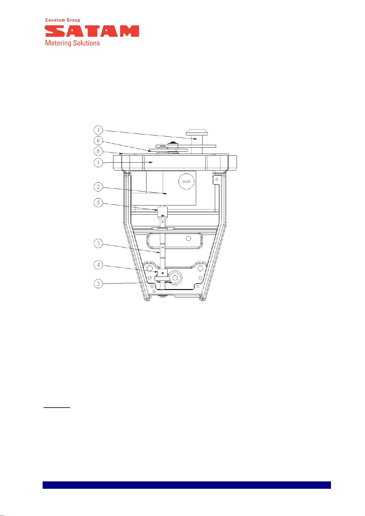
Low flow setting
- Remove the cover (1)
- Adjust the setting by changing the position of the roller using the 19 mm flat spanner and a 10 mm
spanner.
- Rotate the eccentric in a clockwise direction to increase the low flow rate
- Rotate the eccentric in an anticlockwise direction to reduce low flow rate
- A non closing of the valve can be due to a too low set up of the low flow rate
- In stop state, there must be a clearance between the roller and the cam

Printed on 26/04/12 11/15 U514986-e Revision 4
4.3. 3 ways valve operation
1. Insert a ticket in the ticket printer
2. Choose the outlet pipe required (either via the front (B) or the back (A) of the valve) by using the
lever (1).
a) lightly pull the lever (1) and position it in relation to the outlet pipe required (position A or B)
and put the lever (2) in a open position 0.
b) block the ticket printer by turning the meter head button one full turn.
This operation results in :
- The ticket being locked in the printer
- Printout on the ticket of a first line of figures
- Resetting of the figures indicated on the register
- The selected setting of the 3-way-valve being locked
3. Delivery can now take place, or flow rate modified, using the control lever (2) of the 3 ways valve.
At the end of delivery the user turns the meter head push button a full turn which results in :
- A second row of figures being printed on the ticket
- The ticket is released
- The 3 way valve is released.
(without modification of the information display on the register)
The complete cycle can begin again.
F
O
F
O
B
A
1
2
+
-
45°
Position Petit Débit
1
er
Cran d’ornement
1
Réglage du petit débit par
rotation du galet excentrique
avec une clé extra plate de 19
et une clé plate de 10

Printed on 26/04/12 12/15 U514986-e Revision 4
5. Metrological check - Adjustment operation
5.1. Metrological check
Current DIRRECTE and LNE (Weights and Measures) legislation require :
. Metrological inspection of meter at operation start-up
. Subsequent yearly inspections.
If during gauging the meter is found to be outside the accepted error, it is possible to re-calibrate the
meter using the AB 35 calibrating mechanism. For meters using an electronic calculator, the re-calibration
is made by adjustment of the calculator correction factor (see annex 2 of document U513237 for the
RUBIS, U516318 for the l’EQUALIS L and U516703 for the EQUALIS MPC).
5.2. Adjustment procedure
A - TEST
1 - Carry out a test run at the installation's maximum rate of flow using a 500 litres gauge
2 - Note the volumes indicated on the Indicating device and on the gauge respectively
(example : 500 litres at the indicating device and 498.5 litres at the gauge)
3 - Calculate the difference indicating device reading – gauge reading
(example : 500 - 498.5 = 1.5 litres, i.e. a difference of + 3 litres for 1000 litres, = 3‰ )
B - ADJUSTMENT OPERATION
1 - Unseal and remove the cover (1)
2 - Unscrew the two screws (2)
3 - Open the cover from the bottom
4 - Carry out adjustment (see § C)

Printed on 26/04/12 13/15 U514986-e Revision 4
5 - Check adjustment by carrying out a new gauging test
6 - Put the cover back in place and tighten the screws.
7 - Re-seal
C - PRINCIPLE OF ADJUSTMENT
Reminder : 1 notch of the calibration screw (3) = 0.25‰ in whatever direction adjustment is made.
1 - Note the position of the calibrating screw.
2 - Turn the screw the appropriate number of notches in the direction required to obtain the required
adjustment :
difference (in ‰) / 0.25 = number of notches
In the above example, 3 litres must be added to the gauge. Therefore we must turn the calibration screw
(3) in the positive direction (+) of :
3 (‰) / 0.25 = 12 notches, in the anticlockwise direction.
D – ADJUSTMENT OF THE ELECTRONIC CALCULATOR RUBIS OR EQUALIS
See calibration instructions U513237 For the Rubis
See calibration instructions U516318
For the Equalis L
See calibration instructions U516703
For the Equalis MPC

Printed on 26/04/12 14/15 U514986-e Revision 4
6. Servicing
6.1. General
Periodic maintenance is required at least once a year.
Some operations on the meter require the device to be unsealed. Only a Company approved by Weights
and Measures may do this.
Important :
We strongly advise against the use of a high pressure water jet to clean the measuring unit, as this could
seriously damage the metering unit..
6.2. Quarterly periodic inspections
The following checks must be carried out at least once a quarter by the user.
6.2.1. Strainer baskets
The strainers installed upstream of the meter should be inspected.
Reminder :
- Filtration for Jet A1 : 50 microns
- Filtration for Gasoline, Premium, Super : 70 microns
- Filtration for Diesel oil, Gas oil, FOD : 200 microns
6.2.2. Measurement chamber MA21-12
Check that no leakage is occurring around the measuring chamber (piping, covers, outlet shaft – leakage
from the outlet shaft would be visible on the lower part of the AB 40 transmission device).
6.2.3. Ticket Printer
Make sure there are no particles or pieces of ticket caught in the ticket printer mechanism.
6.3. Yearly inspections
6.3.1. Measurement chamber MA21-12
The actual measuring chamber itself does not require preventive maintenance.
Any intervention necessary must be carried out by a repairer approved by SATAM with test equipment
approved for basic inspections of the meter.
6.3.2. Mechanical indicating device
See the Installation and Operation Manual.

Printed on 26/04/12 15/15 U514986-e Revision 4
6.3.3. Transmission device AB40
The worm screw and gear (1 & 2) :
- Check clearance
- Clean and grease
Bearings (4 & 5) on shaft (3) :
- Check wear
- Clean and grease
In the upper part of the AB40 :
- Check the rings and the drive gear shaft leading to the mechanical indicating device
- Clean and grease the drive gears assembly
N.B : The AB35 adjustment device does not require preventive maintenance.
notice very important
6.3.4. REMARK VERY IMPORTANT
We strongly advise a
gainst the use of a high pressure water jet to clean the measuring unit,
as this could seriously damage the metering unit.
This manual suits for next models
1
Table of contents
Other SATAM Measuring Instrument manuals
Popular Measuring Instrument manuals by other brands

NLS
NLS XL-1 instructions

Datalogic
Datalogic Controller SC6000 installation manual

SICK
SICK Lector85x Operator's manual

Toledo Transducers
Toledo Transducers MoniTTor N269 Installation and operation manual

Pessl Instruments
Pessl Instruments iMETOS mMETOS Blue user manual

Purafil
Purafil ONGuard 4000 quick start guide