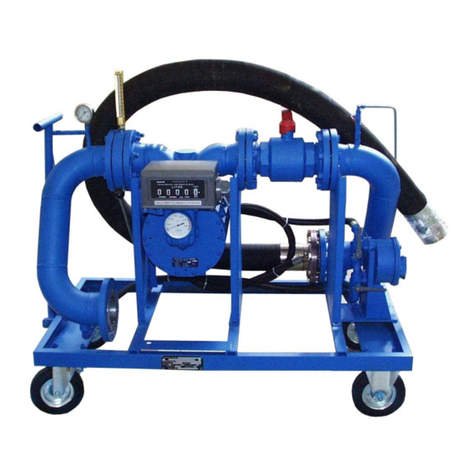
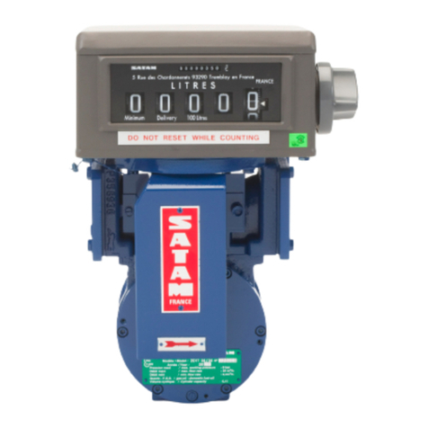
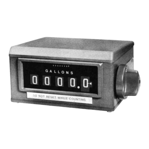
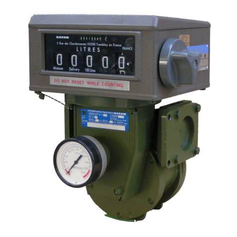
SATAM ZCE 18 24 User manual

SATAM Siège Social : Paris Nord II – Bât. Le Gauguin – 47, allée des Impressionnistes
Usine de Falaise – Avenue de Verdun – B.P. 129 – 14700 FALAISE – France B.P. 85012 – Villepinte – 95931 Roissy C.D.G. Cedex - France
Tél. : +33 (0)2 31 41 41 41 Tél. : +33 (0)1 48 63 02 11
Fax : +33 (0)2 31 40 75 61 Fax : +33 (0)1 49 38 41 01
SIRET 495 233 124 000 17 SA au capital de 6 037 000 € – RCS Bobigny B 495 233 124
CODE APE 2813 Z SIRET 495 233 124 000 17 – Code APE 2813 Z – N°TVA : FR 48 495 233 124
FLOWMETER
ZCE 18 24 & ZCE 18 42
EMS 12 & EMS 24 & EMS 48
Description – Installation – Implementation–
Maintenance
U509001-e – Revision 1 – 15 July 2009
This document comprises
11
pages (fly page included)
This document is the property of SATAM
And may not be given to third party without prior authorization
SATAM reserves to itself the right to alter this document without prior notice
IN ACCORDANCE WITH the European Directive 94/9/CE - ATEX

FLOWMETER
ZCE 18 24 &
ZCE 18 42 &
EMS 12 & EMS 24 & EMS 48
ON LORRY AND FIXED INSTALLATION
FOR HYDROCARBONS
Contents
1.
Alternative EMS and ZCE 18 Models.............................................................................3
2.
General ...............................................................................................................................4
3.
Description .........................................................................................................................4
3.1. Dimensions ............................................................................................................................... 4
3.2. Components.............................................................................................................................. 5
3.3. Conditions of Use ..................................................................................................................... 6
Maximum and minimum temperatures................................................................................................ 6
Environmental classification................................................................................................................ 6
4.
Installation..........................................................................................................................7
4.1. Delivery .................................................................................................................................... 7
4.2. Checking Procedure.................................................................................................................. 7
4.3. Implementation......................................................................................................................... 7
4.3.1.
Hydraulic Connections.................................................................................................................... 7
4.3.2.
Earthing........................................................................................................................................... 7
4.3.3.
Electrics........................................................................................................................................... 7
4.4. Installation Plans....................................................................................................................... 8
4.4.1.
Mechanical EMS and ZCE 18......................................................................................................... 8
4.4.2.
EMS and ZCE 18 pneumatic control .............................................................................................. 9
5.
Implementation................................................................................................................10
6.
Maintenance.....................................................................................................................11
15/07/09 2/11 U509001-e Revision : 01

1. Alternative EMS and ZCE 18 Models
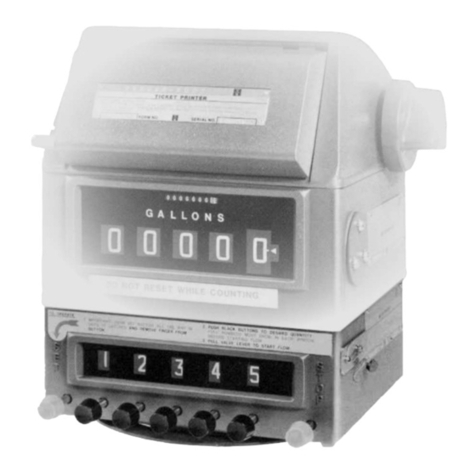
EMS or ZCE 18 EQUALIS L
EMS or ZCE 18 RUBIS
EMS or ZCE 18 Reader head
VEEDER ROOT
15/07/09 3/11 U509001-e Revision : 01
Temp┼raturede fonctionnement:-25░C╚+55Temp┼raturede fonctionnement:-25░C
Fr┼quence maxi:1666 Hz
-25░<Ta<55-25░C
CE
Type:
EEx ib IIA T4
LCIE 03 ATEX 6178 X
TOKHEIMSOFITAM APPLICATIONS
0081 II 2 G
20
n░s┼rie
serialn░
Falaise
MARCHE
STOP
FALAISE
Ann┼e 20
N░de d┼cision: 00.00.510.004.1
N░s┼rie:
Mod╔le : RUBIS
INDICATEUR ELECTRONIQUE
DISPOSITIF CALCULATEUR
TOKHEIM SOFITAM APPLICATIONS
sont contr┬l┼es par l'Etat
dans les conditions de mesure
Seules les indications de volume
5 rue des Chardonnerets
93290 TREMBLAY-en-FRANCE
TOKHEIM SOFITAM APPLICATIONS
EM12EM6
EM11
EM10
EM9
EM8EM1
EM2
EM5
EM4
EM3
EM7
EMS or ZCE 18 EMR 3

2. General
The EMS and ZCE 18 metering units are designed to deliver hydrocarbon liquids at a kinematic
viscosity of less than 20 mm2/s, industrial oils and fatty acid methyl esters for diesel motors,
ethanol delivered by tanker or self-service area.
This section sets out the necessary information for receipt, installation and implementation of the
EMS & ZCE 18 metering equipment. The additional information sheets for each of the
accessories are provided separately.
3. Description
3.1. Dimensions
4 trous M8 ARRIERE : G 2'' femelle
G 1''
476
330
345
TUBE3":80x88.9
662
34
31,6
600
14 AVANT: coupling DN 65
373
174
42
48,6
533
863
526
15/07/09 4/11 U509001-e Revision : 01

3.2. Components
The EMS and ZCE 18 control delivery meters are made up of the following components:
15/07/09 5/11 U509001-e Revision : 01
Temp┼rature de fonctionnement: -25░C ╚+55Temp┼rature de fonctionnement: -25░C
Fr┼quence maxi: 1666 Hz
-25░<Ta<55-25░C
CE
Type:
EEx ib IIA T4
LCIE 03 ATEX 6178 X
TOKHEIM SOFITAM APPLICATIONS
0081 II 2 G
20
n░s┼rie
serial n░
Falaise
MARCHE
STOP
FALAISE
Ann┼e 20
N░de d┼cision: 00.00.510.004.1
N░s┼rie:
Mod╔le : RUBIS
INDICATEUR ELECTRONIQUE
DISPOSITIF CALCULATEUR
TOKHEIM SOFITAM APPLICATIONS
sont contr┬l┼es par l'Etat
dans les conditions de mesure
Seules les indications de volume
5 rue des Chardonnerets
93290 TREMBLAY-en-FRANCE
TOKHEIM SOFITAM APPLICATIONS
4
1
2
3
5
6
7
8
9
10

1 An air separator:
a) For tankers:
A SATAM FS 24 or EC 36-1 air separator filter including a protection filter in
stainless steel (200µ for petrol and 450µ for diesel).
b) For a fixed dispenser:
An EC 27-40 type SATAM air separator for flows greater than 24 m
3
/h and for
underground storage tanks.
2 A flow counter model : ZC 17 12/12 or ZC 17 12/24 or ZC 17 12/25
ZC17 24/24 or ZC 17 24/48
ZCB 17 24/24 or ZCD 17 24/48
3 A VR type 7887 or Kienzle type M indicator graded in liters or an EQUALIS L,
RUBIS or EMR 3 type electronic calculator (4)
5 In the case of EMS 48 and ZCE 18-42, a sensor. Where a pneumatic authorization tap
XAD 54 is used, the sensor is incorporated in the body of the tap. This sensor enables the
detection of air.
Available on request:
6 A valve of authorization XAD 39 mechanical or electric or a valve of authorization XAD
54 pneumatic.
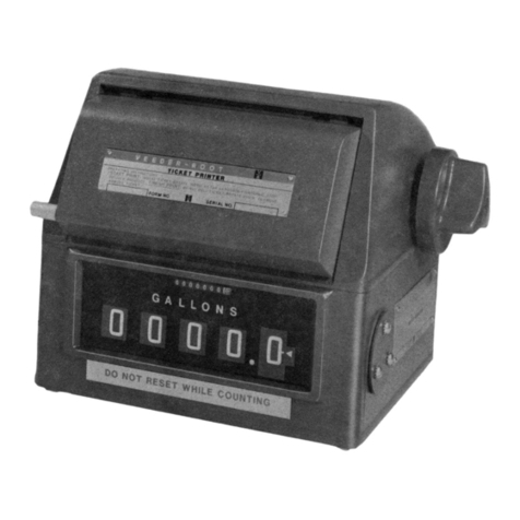
7 A totalizer ticket printer 7498 or O. start 7951
8 A predetermining counter 7889 on request.
9 A three way tap XAD 46 (9)
10 If necessary provided with a valve box.
The fixed installation is completed by a micro filter water separator for flight or diesel motors.
3.3. Conditions of Use
Maximum and minimum temperatures
Temperature Limits
Electronic Mechanical
Maximum temperature 55°C 55°C
Minimum temperature - 25°C - 40°C
Environmental classification
Tanker and fixed unit +
counter Means of provision
Mechanical environnement M2 M2
Electromagnetic environnement E3 E3
Damp environnement H3 H1
15/07/09 6/11 U509001-e Revision : 01

4. Installation
4.1. Delivery
The apparatus is generally delivered on a wooden plinth packaged in a cardboard box made
especially for its transportation to ensure the maximum safety.
If however on receipt of the goods it looks as though they have sustained serious damage (which
normally shows by evidence on the outside of the packaging) reservations must be notified to
the transporter without delay, and SATAM must be advised.
4.2. Checking Procedure
Check that the EMS or ZCE 18 counter units to be installed correspond with the product being
provided (shown on the certificate of examination of the model or on the identification plate of
the unit).
Please note:
The rules of the country, concerning a premier category liquid, where the EMS and ZCE 18
counters are installed, must be observed.
4.3. Implementation
The EMS and ZCE 18 units are installed after the pump.
The atmospheric outlet must be connected with a 1” tube to a container or a recovery tank for the
fixed installations.
4.3.1. Hydraulic Connections
The entrance connection of the EMS and ZCE 18 counting unit is made behind the separator
filter by a by a welded flange of Ø 2” (specifically provided by SATAM), for the EMS and ZCE
18 with a three way discharge valve, a female flange of 2” cylindrical gas for the hose and a
threaded male flange connector of 2” ½ to receive the valve box.
4.3.2. Earthing
To allow for a continuous supply of electricity to the measuring unit with the installation, it is
imperative to connect the junction points to « earth » and ensure an earth for the vehicle.
4.3.3. Electrics
Install a 1,6A fuse cut out on the 24 volt supply of the RUBIS electronic indicator, for EQUALIS
L and the EMR 3 the fuse if integral.
15/07/09 7/11 U509001-e Revision : 01

SATAM Siège Social : Paris Nord II – Bât. Le Gauguin – 47, allée des Impressionnistes
Usine de Falaise – Avenue de Verdun – B.P. 129 – 14700 FALAISE – France B.P. 85012 – Villepinte – 95931 Roissy C.D.G. Cedex - France
Tél. : +33 (0)2 31 41 41 41 Tél. : +33 (0)1 48 63 02 11
Fax : +33 (0)2 31 40 75 61 Fax : +33 (0)1 49 38 41 01
SIRET 495 233 124 000 17 SA au capital de 6 037 000 € – RCS Bobigny B 495 233 124
CODE APE 2813 Z SIRET 495 233 124 000 17 – Code APE 2813 Z – N°TVA : FR 48 495 233 124
4.4. Installation Plans
4.4.1. Mechanical EMS and ZCE 18
15/07/09 8/11 U509001-e Revision : 01

4.4.2. EMS and ZCE 18 pneumatic control
15/07/09 9/11 U509001-e Revision : 01

Important :
Fixed Installations
Whatever the type of pump, the motor must always be protected by a circuit breaker situated
on the electricity board, set at the maximum level corresponding to the motor’s power.
It is further recommended that the circuit breaker should include a thermal relay of minimum
power, to avoid the machine starting up again unexpectedly after a short stop for that reason.
A Stop/Start button must be installed close to the delivered unit in a fireproof casing.
5. Implementation
When the hydraulic and electric connections have been made, it is possible to start to start the
counting unit observing the following rules:
- evacuate the unit
- start with a small flow
Attention :
Never lose sight of the dangers in manipulating what is essentially an inflammable product,
and observe the safety rules and regulations for using such apparatus. In particular, smoking is
forbidden; keep an extinguisher close by etc…
• Earth the lorry, boat or plane.
• Turn the indicator to zero by turning its handle. If the machine has a ticket printer,
then turn to zero after inserting the ticket into the slot, the side with writing on facing
downwards, and by turning the handle as far as it will go, the ticket will be punched.
• For those units with an electronic reader, RUBIS, EQUALIS L or EMR 3 refer to the
instructions for use.
• Open the distribution tap.
Using a tanker:
• Unroll the distribution hose, attach the nozzle and open it, turn to zero and if
appropriate punch the ticket.
• In the case of EMR3 start the distribution on the counter, fully open the valves and
open the tank.
• Start the pump.
• With the electronic counter RUBIS or EQUALIS L, the opening of the valves and
the starting of the pump is automatic.
15/07/09 10/11 U509001-e Revision : 01

6. Maintenance
• Check the strainer basket (at least once a month)
Taking out the strainer basket does not require any special tools.
It is imperative to check the strainer basket to avoid too large an amount of impurities which
will cause it to clog up.
In normal conditions of use, this operation should be undertaken at least once a month, but
this can vary, depending on the quality of the product and the amount delivered.
• The reader head unit
Please see the user manual for instructions and maintenance.
• Metrological check of the measuring units
- A metrological check at the time of use is known as a ‘primitive’ check.
- An annual metrological check is known as a ‘periodic’ check.
(These operations are undertaken by appointed companies or by SATAM in the context of the
MID directive)
If during a measuring operation, the most substantial flow exceeds the tolerance, it can be
readjusted by means of the continuous regulating system AB35 or by changing the correction
factor on RUBIS, in the case of EMR3 or on an EQUALIS L the adjustment is automatic.
IMPORTANT NOTICE
In no circumstances may the installation manager ask the manufacturer to undertake this
operation on site.
The fitter has to arrange thus necessarily a capacity of 1000 liter capacity minimum, allowing
to make the metrological control during the starting.
It is not advisable to clean the counter unit using a high pressure device, which could cause
damage to the reader head.
15/07/09 11/11 U509001-e Revision : 01
This manual suits for next models
4
Table of contents
Other SATAM Measuring Instrument manuals
Popular Measuring Instrument manuals by other brands

BEKA
BEKA BA558C manual

Dwyer Instruments
Dwyer Instruments MAFS Series Installation and operating instructions

Aquametro Oil & Marine
Aquametro Oil & Marine Viscomaster Installation and operation manual

Digi
Digi DI-80 Service manual

VMI
VMI VIBER X3 manual

Agilent Technologies
Agilent Technologies 8719ET Service guide