Satel CA-64 SZ User manual

®CODE LOCK
CA-64 SZ
ca64sz_e 06/04
The code lock CA-64 S is a device designed to operate with the CA-64 control panel. It is
used for simple access control to a room provided with a door equipped with an electrically
operated lock. It also monitors the door status (open or locked). Also, the code lock module
may control operation of other devices, for which access control is required. This manual,
which covers typical application of the module, has been written for the module software
version 1.4, the control panel software 1.03.12, and the DLOAD64 program version 1.03.15.
DESCRIPTION OF MODULE
Figure 1
Code lock keypad is provided with 12 keys with permanent or temporary backlit (operating
automatically), and three LEDs described as follows:
•STAND BY (green) – the LED lights when the lock is operated by the control panel and the
door may become opened.
•ACCESS (red) - the LED lights when the door is unlocked.
•DOOR (yellow) – the LED informs on the status of the input that monitors the door position.
The LED lights when the door is open.
When all three LEDs (STAND BY, ACCESS, DOOR) blink in sequence, this indicates missing
communication between the code lock and the control panel. This situation may occur when the
special system initialisation program (STARTER) is running in the control panel, or the code
lock keypad has not been identified by the control panel (service function) or the cable
connecting the code lock keypad to the control panel is damaged.
The way of a code lock keypad operation depends to a large degree on the software installed.
The description of situations, in which the way of code lock operation depends on the program
installed, is marked with the following text in brackets: (service setting).
STAND BY
ACCESS
DOOR
123
6
45
789
0#

2Code lock CA-64 SZ SATEL
MODULE OPERATION
Operation of a door lock (or other device) by means of a code lock keypad includes entering the
USER CODE (4 to 8 digits) and pressing the key marked #or 9. Enter the code by pressing
from 4 to 8 numeric keys one by one, according to the code contents assigned to the user.
The code lock user function:
>CODE # or CODE 9-door opening.
In order to open the door, the user must be authorised to use the code lock. Authorisation is
given by the installer by means of the DLOAD64 computer program or by the alarm system
administrator by means of the GUARD64 computer program.
The possibility to change the code by the user is an additional function of the code lock
keypad (service setting).
Code change by the user is carried out as follows:
Keep pressed for a longer time (approximately 3 seconds) the key with digit 1(LEDs
STAND BY and ACCESS – green and red – start to blink alternately).
Type old CODE and press # (LEDs: STAND BY and DOOR – green and yellow - start to
blink alternately).
Type new CODE and press # (LEDs stop blinking and the module generates
confirmation signal of the function executed).
The control panel may refuse changing the code - it is signalled with two long sounds.
Information on the refusal of code changing is available in the "User’s Manual for CA-64"
(ÆOperation of Control Panel CA-64, ÆPartition Keypad).
When an erratic code is typed three times, the alarm will be activated (service setting).
It is possible to call special alarms (without code entering) from a code lock keypad (service
setting). These functions are started by keeping depressed for approximately 3 seconds, the
keys described below:
9# panic alarm,
90 auxiliary alarm (for example, calling for medical aid),
99fire alarm.

Module installation and starting 3
SIGNALLING
The code lock module communicates with the user visually (by means of three LEDs) and by
sound (by means of the buzzer). Visual signalling is described in the section “Description of the
module”.
Acoustic signals generated by the code lock (this is the basic way the control panel
confirms the operation of code entering, since there is no display at the code lock) are as
follows:
One short beep – confirmation that the key has been pressed.
Two long beeps – the code is not known to the control panel.
Three long beeps – the code (the user) cannot control this lock.
Four short beeps and one long beep – confirmation of the code lock unlocking.
Five short beeps – dependent door is open – the code lock has not been unlocked. In
order to unlock the lock, close the dependent door and enter the code again.
Blinking of the key backlit may be arranged instead of audible signalling (service setting). Beeps
correspond to keypad backlit off pulses, when the backlit is on (automatic or permanent key
backlit), or backlit on pulses, when normally it is off (no key backlit).
MODULE INSTALLATION AND STARTING
The schematic view of part of the board with cable terminals is shown in Figure 2.
The set of switches on the board is used for setting the individual module address.
If the door status monitoring input IN is not used, connect it to ground.
Two NO relay terminals are used for controlling the door electromagnetic lock. These terminals
are galvanically insulated from code lock circuits.
The microswitch, located at the keypad board, is used as anti-tampering protection. When the
module is installed correctly, the spring on the microswitch should be pressed against the wall.
MODULE TERMINALS:
NO - relay terminal
IN - door status monitoring input (NC)
COM - ground
+12V - power supply input
DTA, CLK - expander bus
Figure 2
INSTALLATION
The code lock module may be mounted either directly to the wall or in a metallic OBU-M-LED
casing. This casing is closed by means of a key to make access of unauthorised persons to the
keypad more difficult.
1 2 3 4 5 6 7 8
ON
ADDRESS
NO NO IN COM +12V DTA CLK

4Code lock CA-64 SZ SATEL
MODULE WIRING
NOTE: Disconnect power supply for the whole system before you start to wire the module
to the existing alarm system.
1. Remove the plastic module casing by pressing the clips, which fix the casing bottom.
2. Fix the bottom of plastic casing to the wall. The connecting leads should be passed through
the rectangular opening in this part of casing.
3. Connect the leads of first or second expander bus to the following terminals: DTA, CLK and
COM (first bus: CK1, DT1, COM; second bus: CK2, DT2, COM –as marked at the control
panel main board). As many as 32 modules of different types may be connected to one
single bus.
4. Set the expander address by means of switches. The module address is set with switches
numbered from 1 to 5. The remaining switches (6, 7, 8) are irrelevant. In order to define the
expander address, summarise numbers corresponding to switches set to position ON,
according to the table
Switch number 1 2 3 4 5
Corresponding number 1 2 4 8 16
Examples of addressing:
address
= 4 address
=2+8=10 address =1+8+16=25
These five switches allow to address 32 expanders (numbers from 0 to 31). The
addresses of expanders connected to one, common bus must be unique, and the order of
addressing is optional. It is recommended to address the expanders and modules
connected to one bus in sequence, starting from 0. This will allow avoiding problems when
extending the system.
5. Connect the module power supply to the terminal +12V. Power supply for a keypad may be
provided from a source other than the control panel main board. It may come from a buffer
power pack or another expander with a power pack. Detailed information on wiring are given
in the manual for the CA-64 control panel titled “System description and installation”.
6. Connect the leads of the door status monitoring sensor to IN and COM terminals.
7. Connect door electromagnetic lock leads (or leads for another device) to relay terminals NO.
8. Fix the code lock keypad module to the wall by clasping the plastic casing.
STARTING THE MODULE
1. Switch on the alarm system power supply.
2. Start the communication between the control panel and the computer by calling the function
“Downloading”.
3. Call the function “Identification of expanders” from the LCD keypad (ÁService mode;
ÁStructure; ÁHardware). after identification, the value of all settings is zero or “None”, and
options are switched off. Since the pressing of keys is not confirmed, it seems like the
module does not respond to code entering.
NOTE: During the identification process, the control panel saves into memory the special
number (16 bits), which is used for checking the presence of the module in the
1 2 3 4 5 6 7 8 1 2 3 4 5 6 7 8 1 2 3 4 5 6 7 8

Module installation and starting 5
system. Replacement of the module with another one (even if the same address
is set) without carrying out the identification process again causes alarm (module
tamper – verification error).
4. Program the code lock functions and define the users authorised to use this code lock
module by means of DLOAD64 program.
5. Exit the service mode by saving the data in the FLASH memory.
6. Terminate communication with the computer and save the data with the system settings in a
separate file.
PROGRAMMING OF CODE LOCK KEYPAD SETTINGS
The dialogue window shown in Figure 3 is used for programming of the code lock settings in
the program DLOAD64. Programming is carried out by typing data from the computer keyboard,
selecting the items from the list or marking the options by means of the computer mouse.
The control function is executed by operation of relay NO terminals (electromagnetic switch)
located on the board inside the code lock casing. The relay operates in monostable way. The
basic status of relay terminals (contact) is set with a separate option. Door opening by the user
(CODE # or CODE 9) changes the relay contact status to the reverse one.
Figure 3
♦Name: - the field, where an individual name (16 characters) is assigned to the module.
♦Partition:- the field, where the code lock keypad is assigned to the partition (selected from
the list). This assignment indicates, in which partitions alarms will be signalled (tamper
alarm, alarm from the code lock keypad).

6Code lock CA-64 SZ SATEL
♦LOCK – functions for defining the way of operation of lock control relay.
Fixed ON time – This option sets the operation mode, in which the relay works in a
monostable way. After the user has called the door opening function (CODE 9) the relay
will be activated for the time set in field the “Relay ON time:”, and then switches to its
normal status. Activation time period may be from 1up to 255 seconds.
Fixed ON time – OFF if door open – The relay is active until the door is open (input IN
is disconnected from ground), but no longer than for the “Relay ON time”.
Fixed ON time – OFF if door closed - The relay is active for the duration of door
opening (input IN disconnected from ground), and it is de-activated when the door is
closed (input IN is connected to ground again), but the relay is active no longer than the
“Lock ON time”.
Relay – This option sets a way of relay contacts operation:
àNO - normally contacts NO are open, they close when the relay is activated.
àNC - normally contacts NO are closed, they open when the relay is activated.
Authorization control – opening of the door without using a card or chip (e.g. with
a key) will generate an „Unauthorized door opening” event, and may also be signaled
on the 93 (Unauthorized access) type output.
Alarm on unauth. access – unauthorized opening of a door when the partition to which
the module is assigned is in the armed mode will trigger alarm. Additionally the alarm
may be signaled at the output of 94 type (Alarm – unauthorized access).
Maximum door open time: - Time, after which the module signals an event “door is
opened for long time” to the control panel and activates audible signal, is set in this field.
A time period from 0to 255 seconds may be set.
Dependent on door 1) (or Dependent on door 2)):- The field, where you can select
(from the list) which door must be closed to activate the lock. Door status monitoring is
carried out via input IN at the partition keypad or an input type 57 (technical input – door
monitoring). This function makes it possible to create a “sluice” type passageway.
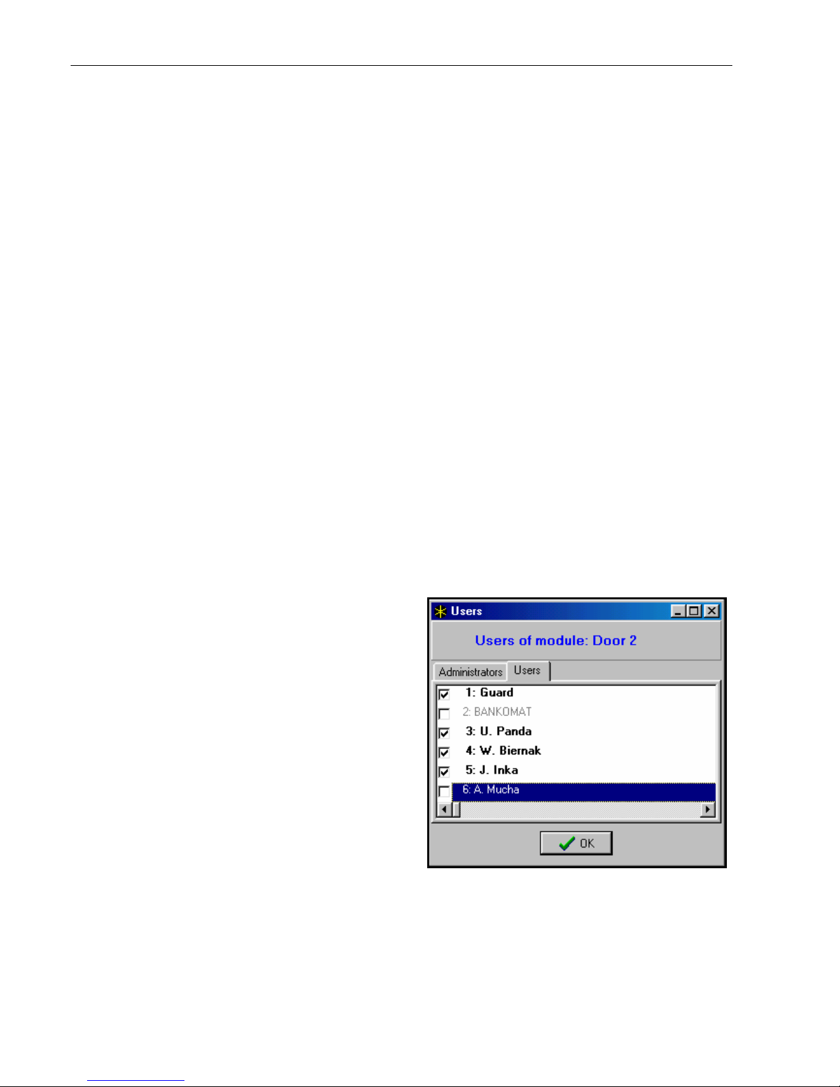
♦Users – When you click with the mouse to this
field, a new dialog window opens (see Figure
4) which is used for setting the list of users
(administrators and ordinary users), who may
use this partition keypad. Mark the user name
to render accessible the partition keypad for
him.
♦Additional features (marking the option will
make accessible the following functions):
FIRE Alarm – When you press the key
designated with 9, you will activate a fire
alarm.
AUX Alarm - When you press the key
designated with digit “0”, you will activate
an auxiliary alarm. Figure 4
PANIC Alarm - When you press the key designated with #, you will activate an attack
alarm.
Silent (PANIC alarm) – When this option is activated, the PANIC alarm started with a
partition keypad does not trigger an audible alarm, but a message is transmitted to the
monitoring station only, and the input type 12 (“silent alarm”) is activated.
Changing access code – When this option is marked, the user code change function is
accessible.

Module installation and starting 7
Partition bypass – entering the sentry code, when the partition is armed, activates
temporary partition bypass
Guard round control – entering the guard code (CODE # or CODE 9) will be treated as
a completion of a guard round.
Alarm 3 incorrect codes – When an erratic code is typed three times, an alarm will be
generated.
No auto-reset after 3 tamp. - each expander automatically blocks its tamper alarm
function after three consecutive (not cleared) tamper alarms, which prevents the same
events from being entered several times into the control panel memory. This option
allows the blocking function to be disabled.
♦Confirming – option determining the way of control panel communication with the partition
keypad user:
Sound – the partition keypad generates the sounds described above in this manual,
section “SIGNALLING”.
Backlight – key backlit blinking is used instead of audible signalling, as described in this
manual section “SIGNALLING”.
♦Backlight – defines the way of operation of key backlit:
No – key backlit is off.
Auto – key backlit is switched on automatically after pressing any key, this function has
additional options:
àNo – key backlit is switched on only after pressing any key,
àZone violation: - key backlit is switched on also when the zone with the number
entered in the field next to the option name has been violated,
àEntry delay, part.: - key backlit is also switched on when the entry delay counting
down is started in the partition with the number entered in the field next to the option
name.
NOTE: Automatic keypad backlit is active for approximately 40 seconds, counting from
the moment of its activation or from the last pressing of any key.
Permanent - key backlit is switched on permanently.
TECHNICAL DATA
Supply voltage .................................................................................................. 10.5V...14V
Maximum current consumption ..................................................................................50mA
Maximum voltage switched over by the relay .................................................................24V
Maximum current switched over by the relay ....................................................................2A
Dimensions .................................................................................................. 80x145x26 mm
Latest EC declaration of conformity and product approval certificates can
be downloaded from our Web site www.satel.pl

8Code lock CA-64 SZ SATEL
SATEL sp. z o.o.
ul. Schuberta 79
80-172 Gdańsk
POLAND
tel. + 48 58 320 94 00
info@satel.pl
www.satel.pl
Table of contents
Other Satel Lock manuals