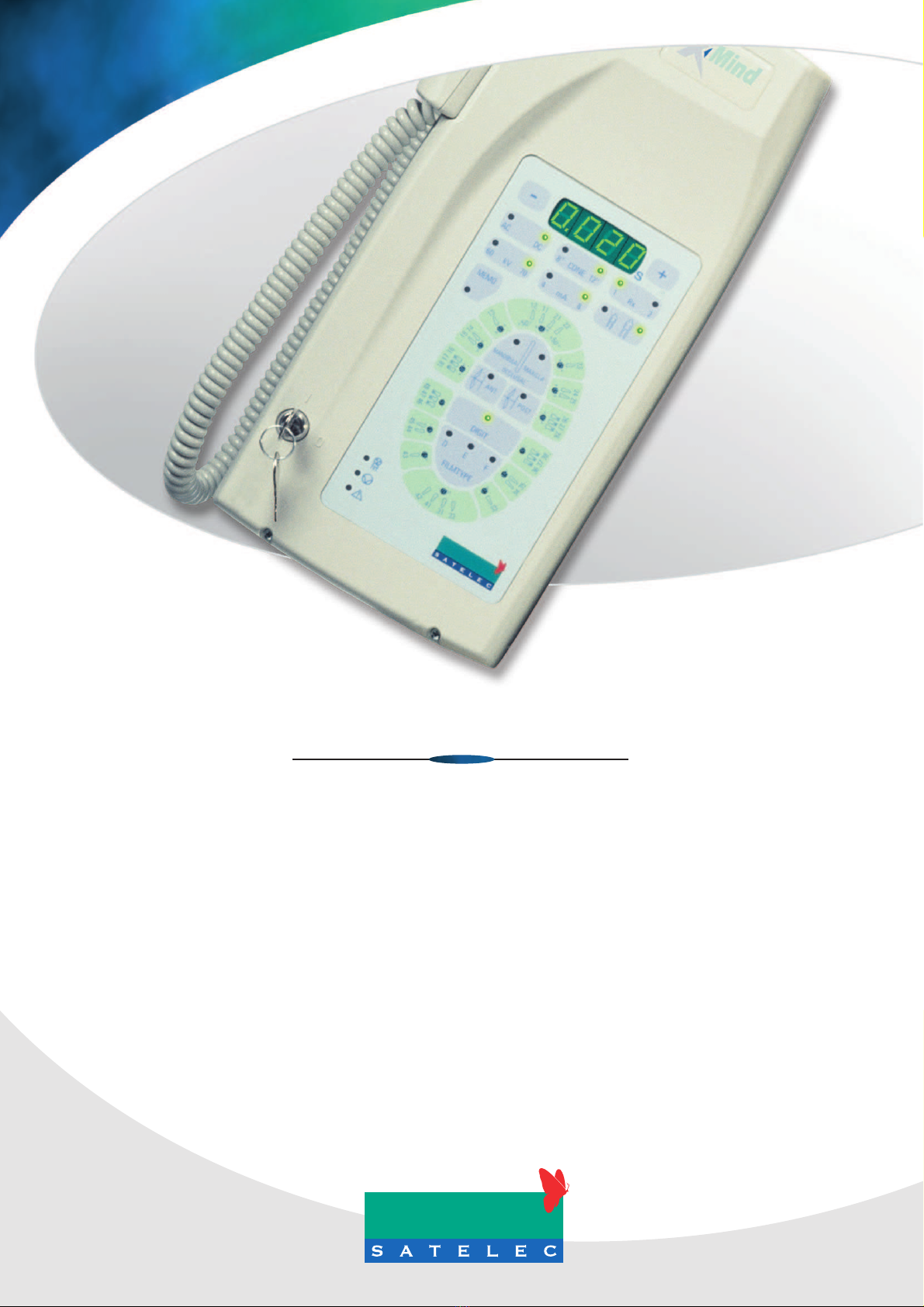
Satelec X-Mind DC User manual

X-Mind®DC
Installation manual / Manuel d’installation
Installationshandbuch / Installatiehandleiing

X-MindDC
Intraoral X-ray system at constant potential
INSTALLATION & MAINTENANCE MANUAL
This manual should always be kept in proximity to the device

2
2
X
X-
-M
Mi
in
nd
d®
®
D
DC
C
INTRODUCTION page 2
SUMMARY page 3
PRELIMINARY INFORMATION page 4
INSTALLER INFORMATION page 5
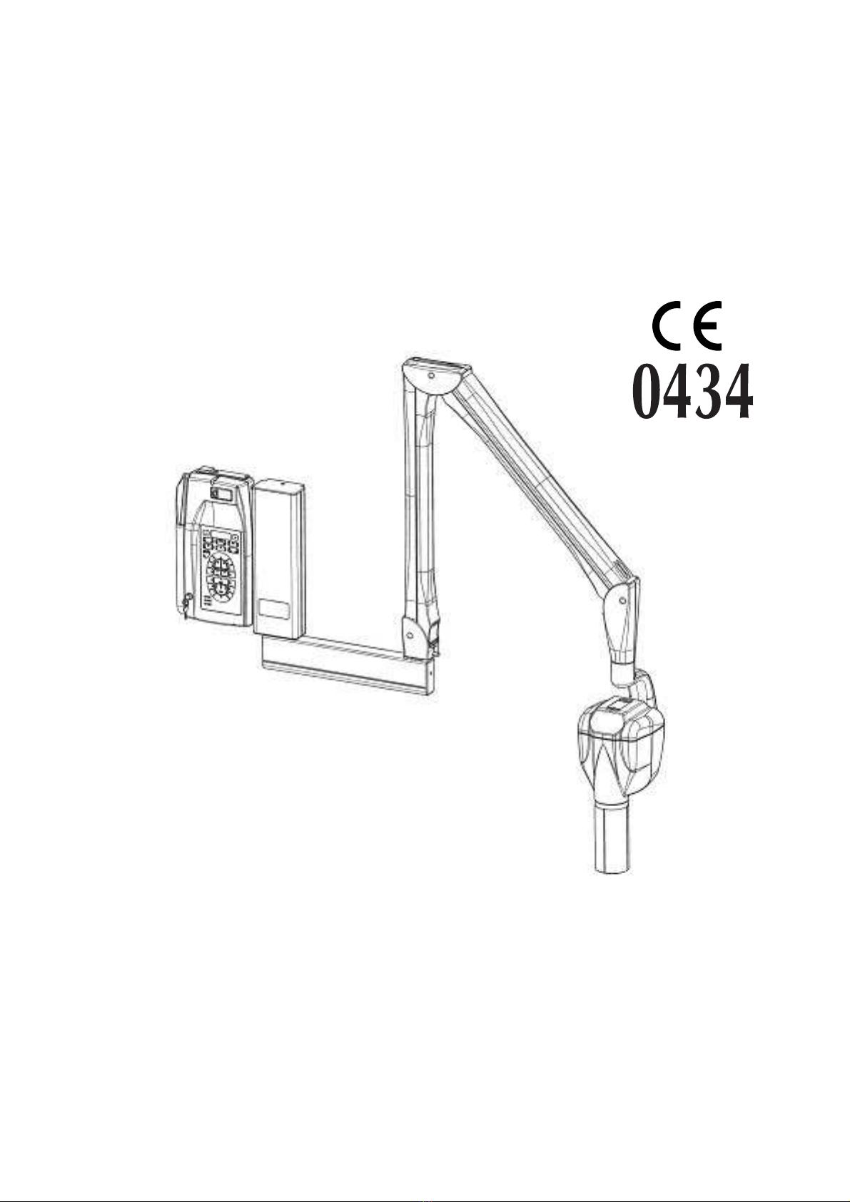
1. “X-Mind DC” X-RAY SYSTEM page 6
2. IDENTIFICATION TAGS page 7
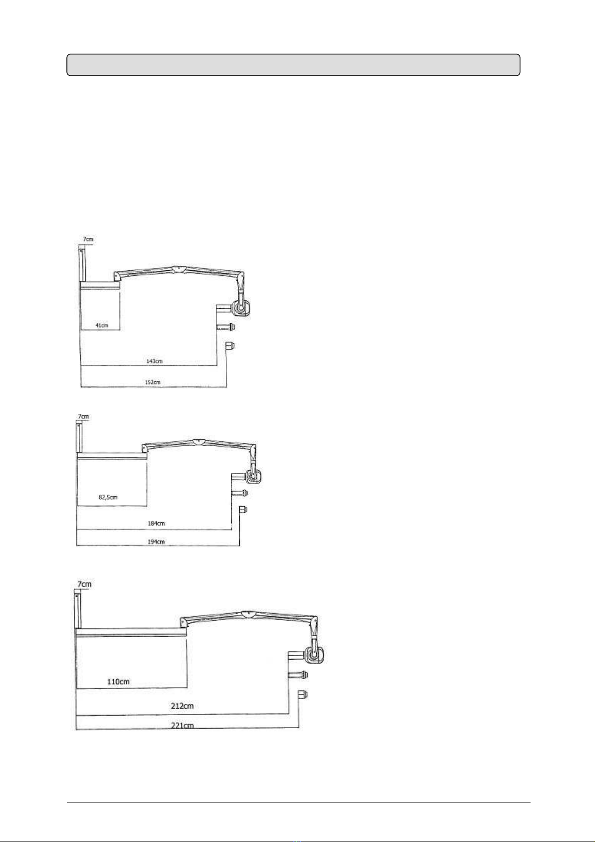
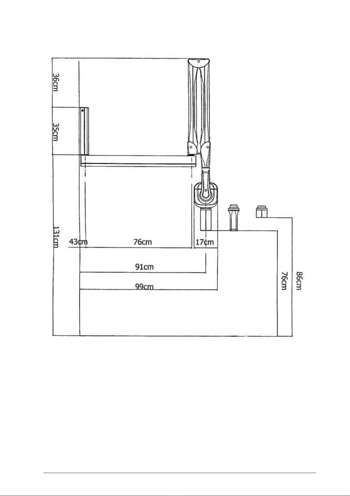
3. OVERALL DIMENSIONS page 8
4. INSTALLATION SPECIFICATIONS page 12
5. INSTALLATION page 15
5.1 UNPACKING page 15
5.2 ASSEMBLING THE WALL PLATE page 16
5.3 ASSEMBLING THE BRACKET page 18
5.4 ASSEMBLING THE PANTOGRAPH-TYPE ARM page 20
5.5 CONNECTION TO THE FEEDING TERMINAL BOARD page 21
5.6 ASSEMBLING THE TUBEHEAD page 24
5.7 BALANCING THE PANTOGRAPH-TYPE ARM page 27
5.8 ASSEMBLING THE “X-Mind DC” TIMER page 30
5.9 TIMER ELECTRIC CONNECTION page 32
6. CONTROL PANEL page 34
7. SYSTEM CONFIGURATION page 36
8. CHANGING THE CONFIGURATION page 38
9. START-UP page 40
10. CHECKING THE INSTALLATION page 41
11. CHECKING THE EXPOSURE FACTORS page 43
12. DIAGNOSTICS page 44
13. CALIBRATION page 45
13. ERROR MESSAGES page 46
14. FUSE REPLACEMENT page 48
15. MAINTENANCE page 49
16. CLEANING OUTER SURFACES page 50
17. SHOULD A REPAIR BECOME NECESSARY page 51
18. DISPOSAL page 51
19. ATTACHMENTS page 52
SUMMARY

X
X-
-M
Mi
in
nd
d®
®
D
DC
C
3
3
Before beginning to use the “X-Mind DC” X-ray system, instructions contained herein should be
carefully read and followed so as to obtain the best possible performance.
Always pay close attention to the CAUTION, WARNING, and PLEASE NOTE messages when
operating the system.
LEGEND
CAUTION
The word CAUTION refers to events which might compromise the operator's personal safety
or cause injuries to people.
WARNING
The word WARNING refers to events which might compromise the radiographic system’s
performance.
PLEASE NOTE
The words PLEASE NOTE refer to special indications to facilitate maintenance or make
important information clearer.
PRELIMINARY INFORMATION

4
4
X
X-
-M
Mi
in
nd
d®
®
D
DC
C
CAUTION
The installer is responsible for the installation, with regards to the system safety and
operation.
For safe and reliable installation of the “X-Mind DC” X-ray system it is advisable to:
Check that the voltage mentioned in the rating plate matches the line voltage
Install the “X-Mind DC” X-ray system according to the procedures described in this
manual
Provide the user with any information regarding the use of the “X-Mind DC” X-ray system
pursuant to the manual
Certify the work done by a Statement of Compliance
Return the duly filled in warranty certificate to “SatelecS.A.S”: if this is not done, the
warranty is not valid
INSTALLER INFO
R
MATION

X
X-
-M
Mi
in
nd
d®
®
D
DC
C
5
5
The “X-Mind DC” X-ray system (Fig. 1) consists of:
TUBEHEAD
SPACER CONE
PANTOGRAPH-TYPE ARM
TIMER
WALL PLATE
BRACKET
OPTIONAL
− long 12” (31 cm) cone
− short 8” (20 cm) cone
− long cone 12” (31 cm) with a rectangular section sized 44x35mm
− second “CONTROL BUTTON” with extension cable
− RX signaling lamp for external use: X-Mind LIGHT
− remote control button: X-Mind ECB
Fig. 1
1. “X-Mind DC” X-RAY SYSTEM

6
6
X
X-
-M
Mi
in
nd
d®
®
D
DC
C
The identification tags on the tubehead, on the timer and on the cone indicate the model name,
the serial number, the manufacturing date and the symbols of the main technical
characteristics.
ID TAG OF THE
“X-Mind DC”
TUBEHEAD
ID TAG OF THE
“X-Mind DC”
TIMER
ID TAG OF THE LONG 12” CONE
ID TAG OF THE SHORT 8” CONE
ID TAG OF THE RECTANGULAR CONE
GRADUATED SCALE TAG ON TUBEHEAD
Pictograms used
This symbol guarantees that the X-ray system complies with the regulations
contained in the European Directive EEC 93/42 regarding Medical Devices
The degree of protection against direct and indirect electric contacts is B type
Refer to Manual's instructions
N “NEUTRAL" power supply wire
L “PHASE" power supply wire
TGround cable
2. IDENTIFICATION TAGS

X
X-
-M
Mi
in
nd
d®
®
D
DC
C
7
7
Fig. 1A, 1B, 1C give the overall dimensions of the possible supply conditions:
SHORT BRACKET (optional) length 41 cm - 16.2”
STANDARD BRACKET length 82,5 cm - 32.5”
LONG BRACKET (optional) length 110 cm - 43.5”
SHORT BRACKET 41 cm Fig. 1A
STANDARD BRACKET 82.5 cm Fig. 1B
LONG BRACKET 110 cm Fig. 1C
3. OVERALL DIMENSIONS

8
8
X
X-
-M
Mi
in
nd
d®
®
D
DC
C
Fig. 2, 3A, 3B, 3C e 4show the typical dimensions of the X-ray system:
STANDARD BRACKET 82.5 cm
Fig. 2

X
X-
-M
Mi
in
nd
d®
®
D
DC
C
9
9
STANDARD BRACKET 82.5 cm Fig. 3A
Fig. 3B Fig. 3C
SHORT BRACKET 41 cm LONG BRACKET 110 cm

1
10
0
X
X-
-M
Mi
in
nd
d®
®
D
DC
C
Fig. 4

X
X-
-M
Mi
in
nd
d®
®
D
DC
C
1
11
1
WARNING
Prior to installing the X-ray system the Office Owner must ascertain that:
the environment, the electrical system and the power supply comply with the
requirements specified, otherwise he must provide the required adjustment works.
1. ENVIRONMENT REQUIREMENTS
a. The installation environment must be of appropriate width.
Using the sizes and overall dimensions provided (refer to §3 “OVERALL DIMENSIONS”),
ensure that no obstacles are present while positioning the X-ray system
b. The environment must not be subject to explosion risks and must not be pressurized
c. While operating, the ambient temperature must range within +5°C and +40°C
d. The storage temperature must range within -15°C and +50°C
e. The relative humidity must range within 25 % and 75 %
2. SUPPORTING WALL REQUIREMENTS
a. The X-ray system supporting wall must be able to stand 200 kg tear at every point
PLEASE NOTE
The nature and consistency of the wall must be checked and if required, seek the
support of a brickwork expert. Walls of uncertain consistency must be reinforced with
a buried counter plate or with a sandwich type system.
3. ELECTRICAL SYSTEM REQUIREMENTS
a. The electrical system must comply with regulations in force
b. The electrical system must be able to supply the power and voltage required in the
Manufacturer's rating plate of the X-ray system as shown in Chart 1
CHART 1
MANUFACTURER’S RATING PLATE 230 V ±15%
115 V ±15%
RATED LINE VOLTAGE 230 V 115 V
MINIMUM VOLTAGE 196 V 98 V
MAXIMUM LINE VOLTAGE 264 V 132 V
FREQUENCY 50/60 Hz 50/60 Hz
ELECTRICAL
SYSTEM
POWER ABSORBED DURING EXPOSURE 850 W 850 W
4. INSTALLATION SPECIFICATIONS

1
12
2
X
X-
-M
Mi
in
nd
d®
®
D
DC
C
4. ELECTRICAL LINE REQUIREMENTS
a. The electrical line must be "single-phase" type
b. It is essential that a 16A – 250V, magnetothermal differential switch be fitted
upstream of the X-ray system, with differential protection In<= 30mA
(refer to §20 “ATTACHMENTS”)
c. The power cords of the timer and the tubehead connection conductors with must be
two-pole + ground, and in proportion to the length of the power cord, as shown in
Chart 2
CHART 2
POWER SUPPLY VOLTAGE
MINIMUM
CONDUCTOR
SECTION
MAXIMUM
LINE
LENGTH
1.5 mm210 meters
196V to 264V 2.5 mm220 meters
1.5 mm210 meters
98V to 132V 2.5 mm220 meters
PLEASE NOTE
For longer lines, the cord section must be increased in proportion.
d. The communication cables (C11, C12 – C21, C22) between the timer and X-Ray must
be two-pole, twisted and shielded with >0.25 mm2section (example: Belden 9501
type)
e. The cables (S11, S12 – S21, S22) connecting the timer and the signal lamps located
outside the surgery must be two-pole > 0.5 mm2
f. The electrical line characteristics must comply with Chart 3
CHART 3
LINE VOLTAGE 230 V ±15%
115 V ±15%
MAXIMUM LINE VOLTAGE DROP 3% 3%
ELECTRICAL
LINE
MAXIMUM LINE APPARENT RESISTANCE 0.5 ohm 0.5 ohm

X
X-
-M
Mi
in
nd
d®
®
D
DC
C
1
13
3
5. ELECTRICAL CONNECTIONS
WARNING
Prior to installing the X-ray system, it is advisable that all the electrical connections be in
place.
Timer electric connections
CAUTION
According to the relevant standard, the timer must be installed in a position allowing the
operator to always control the X-ray exposure.
On the timer installation wall, suitable conduits for the following electric cables must be
provided, pursuant to the electrical installation diagram (refer to §20 “ATTACHMENTS”):
a. Timer electrical cables
(refer to §5.9 “TIMER ELECTRIC CONNECTIONS”)
b. Cables connecting the timer and the tubehead
(refer to §5.9 “ TIMER ELECTRIC CONNECTIONS ”)
c. Cables connecting the timer and the RX signal lamp/s for external use:
X-Mind LIGHT (OPTIONAL)
d. Cables connecting the timer and the remote control button:
X-Mind ECB (IF PROVIDED)
Tubehead electrical connections
On the wall plate installation wall, a suitable conduit for the cable connecting the timer
and tubehead must be provided
(refer to §5.5 “CONNECTION TO THE POWER SUPPLY TERMINAL BOARD”)

1
14
4
X
X-
-M
Mi
in
nd
d®
®
D
DC
C
CAUTION
The “ X-MindDC
X-ray system must be installed by professionally trained technicians,
who must be able to certify their work with a Statement of Compliance.
WARNING
Prior to installing the X-ray system, it is advisable to ensure that all needed requirements
have been met (refer to §4 “INSTALLATION SPECIFICATIONS”)
The components of the “ X-MindDC ” radiographic system are duly packed within a carton box,
as shown in the following sketch (Fig. 5):
D DOCUMENTS: INSTRUCTION MANUAL, INSTALLATION & MAINTENANCE MANUAL, AND WARRANTY CARD
X-MindDC TUBEHEAD PACKAGING
X-MindDC TIMER + RX SIGNALING LAMP FOR EXTERNAL USE X-MindLIGHT (OPTIONAL) + REMOTE
CONTROL BUTTON X-MindECB (OPTIONAL) PACKAGING
PANTOGRAPH-TYPE ARM PACKAGING
WALL PLATE + BRACKET PACKAGING
PLEASE NOTE
Prior to installation, duly check all components.
PLEASE NOTE
The carton and the polystyrene foam can be completely recycled and can be disposed of by
authorized recycling companies.
PLEASE NOTE
The original packaging should be stored in the event the equipment is returned for repairs.
5. INSTALLATION
5.1 UNPACKING

X
X-
-M
Mi
in
nd
d®
®
D
DC
C
1
15
5
WARNING
To fix the wall plate, DO NOT use plastic or rubber anchor screws.
For cement or solid/hollow brick walls, use metal anchor screws Ø12 (NOT included).
ASSEMBLY INSTRUCTIONS (Fig. 6)
1. Take the wall plate out of the packaging (refer to Fig. 5) and take the drilling template
2. Position the drilling templateon the X-ray system installation wall, at the required
height (130 cm from the base is the suggested height)
3. Secure the template with adhesive tape
4. Check the holes for vertical and horizontal alignment, using a plumb line
5. Mark the wall plate anchor holes
6. Mark the holes for the electric cables connecting the timer to the tubehead
PLEASE NOTE
To prevent any flaking in the white coat and to control the center distances between the
holes, it is advisable to start drilling with a Ø7 bit, increasing this size gradually.
7. Drill the wall plate anchor holes
8. If required, drill the holes for the electric cables connecting the timer to the tubehead
9. Remove the template and insert the suitable anchor screws, according to the wall’s
characteristics
10. Unscrew the screw and remove the plug from the wall plate
11. Withdraw the sliding cover
12. Apply the wall plate to the wall and insert the screws with the appropriate washers,
then tighten them alternately
13. Ensure that the wall plate is solidly attached to the wall
PLEASE NOTE
If the wall is not perfectly plumbed, insert a suitable shim between the wall and the wall
plate, in order to prevent warping.
5.2 ASSEMBLING THE WALL PLATE

1
16
6
X
X-
-M
Mi
in
nd
d®
®
D
DC
C
Fig. 6

X
X-
-M
Mi
in
nd
d®
®
D
DC
C
1
17
7
PLEASE NOTE
The brackets come in the following lengths: 41 cm - 82,5 cm - 110 cm
The 82.5 cm and 110 cm brackets are provided with a stop key (Fig. 7A and 7B) to prevent
the electrical cable from twisting.
PLEASE NOTE
Generally, the stop key is installed so that the equipment position at rest is on the right side,
viewed from the front of the wall plate (Fig. 7A).
Should the position at rest be on the left side, the stop key must be rotated by 180° (Fig. 7B).
5.3 ASSEMBLING THE BRACKET
Fig. 7A
Fi
g
. 7
B
WALL

1
18
8
X
X-
-M
Mi
in
nd
d®
®
D
DC
C
After fixing the plate to the wall, assemble the bracket, using the following procedure (Fig. 8):
1. Take the bracket out of the packaging (refer to Fig. 5)
2. Insert the bracket pin into the wall plate (upwards)
3. Insert the supporting rest
Fig. 8
PLEASE NOTE
Prevent all foreign matter (ground, dust, cement, etc. ) from settling on the pin seat.
The pin must slide freely in its seat. If required, thoroughly clean and lubricate with “molikote
D" lubricant.
PLEASE NOTE
Carefully check that the bracket is parallel to the floor, using a water level.

X
X-
-M
Mi
in
nd
d®
®
D
DC
C
1
19
9
ASSEMBLY INSTRUCTIONS (Fig. 9)
1. Take out the pantograph-type arm from the packaging (refer to Fig. 5)
2. Remove the bracket plug by unscrewing the set screw
3. Insert the bracket guard wafer
4. Insert the pantograph group cable into the washer and then the pantograph pin
Fig. 9
5. If required, clean the pin and the washer and lubricate with “molikote D" lubricant
6. Insert the electric cable into the bracket housing
7. Assemble the guard wafer
8. Insert the cable into the bracket and push it until it reaches the pin outlet near the supply
terminal board
5.4 ASSEMBLING THE PANTOGRAPH-TYPE ARM
Table of contents
Other Satelec Medical Equipment manuals