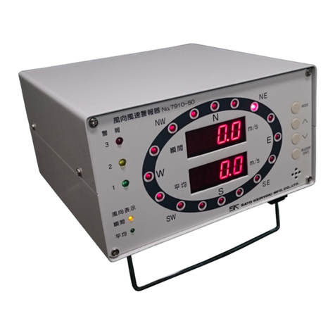
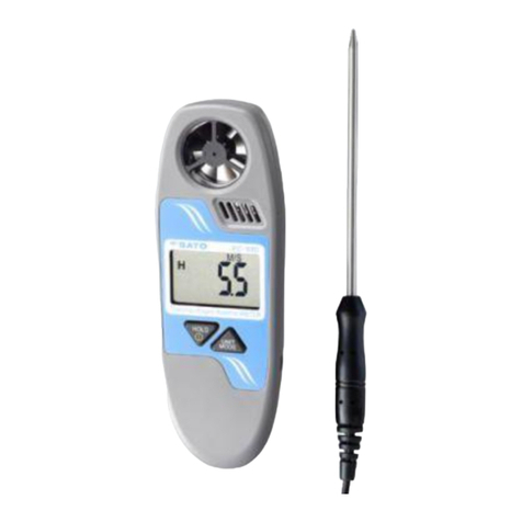
SATO KEIRYOKI 7790-00 User manual
Other SATO KEIRYOKI Measuring Instrument manuals
SATO KEIRYOKI
SATO KEIRYOKI PC-53D User manual

SATO KEIRYOKI
SATO KEIRYOKI PC-9225 User manual

SATO KEIRYOKI
SATO KEIRYOKI SK-130ITH User manual

SATO KEIRYOKI
SATO KEIRYOKI SK-M350-TRH User manual
SATO KEIRYOKI
SATO KEIRYOKI SK-181GT User manual

SATO KEIRYOKI
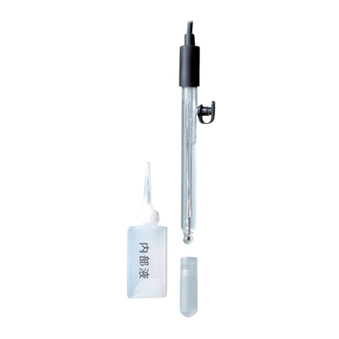
SATO KEIRYOKI 7542-00 User manual
SATO KEIRYOKI
SATO KEIRYOKI 640S-1 User manual

SATO KEIRYOKI
SATO KEIRYOKI PC-7700 II User manual

SATO KEIRYOKI
SATO KEIRYOKI 7610-20 User manual
SATO KEIRYOKI
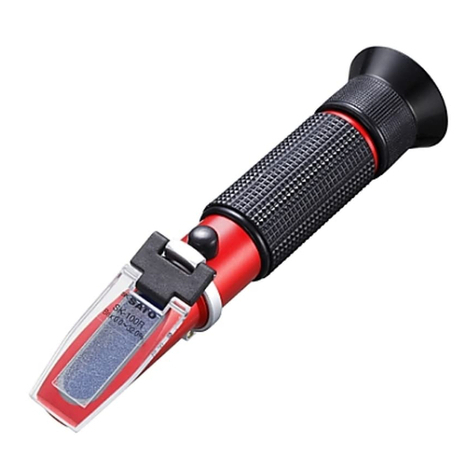
SATO KEIRYOKI SK-100R User manual

SATO KEIRYOKI
SATO KEIRYOKI SK-5RAD-MR User manual

SATO KEIRYOKI
SATO KEIRYOKI 1518-00 User manual

SATO KEIRYOKI
SATO KEIRYOKI PC-7900GT User manual

SATO KEIRYOKI
SATO KEIRYOKI PC-5400TRH User manual
SATO KEIRYOKI
SATO KEIRYOKI PC-5200TRH User manual
SATO KEIRYOKI
SATO KEIRYOKI SK-610PH-II User manual

SATO KEIRYOKI
SATO KEIRYOKI PC-5110 User manual
SATO KEIRYOKI
SATO KEIRYOKI SK-650PH User manual
SATO KEIRYOKI
SATO KEIRYOKI PC-7700II User manual
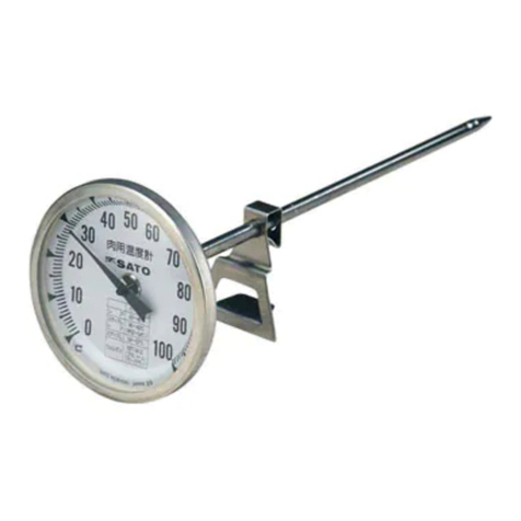
SATO KEIRYOKI
SATO KEIRYOKI 1722-00 User manual
Popular Measuring Instrument manuals by other brands

Powerfix Profi
Powerfix Profi 278296 Operation and safety notes

Test Equipment Depot
Test Equipment Depot GVT-427B user manual

Fieldpiece
Fieldpiece ACH Operator's manual

FLYSURFER
FLYSURFER VIRON3 user manual

GMW
GMW TG uni 1 operating manual

Downeaster
Downeaster Wind & Weather Medallion Series instruction manual

Hanna Instruments
Hanna Instruments HI96725C instruction manual

Nokeval
Nokeval KMR260 quick guide

HOKUYO AUTOMATIC
HOKUYO AUTOMATIC UBG-05LN instruction manual

Fluke
Fluke 96000 Series Operator's manual

Test Products International
Test Products International SP565 user manual

General Sleep
General Sleep Zmachine Insight+ DT-200 Service manual
