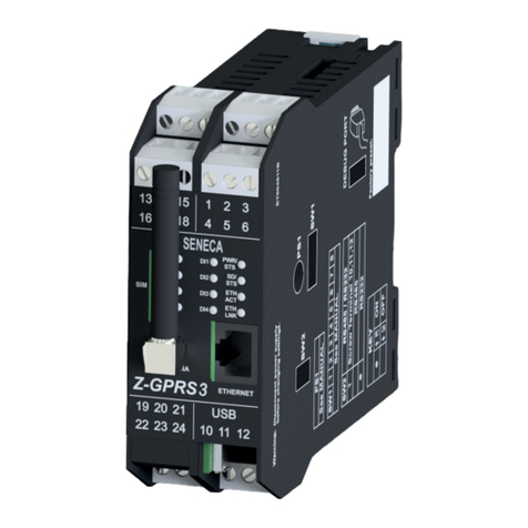
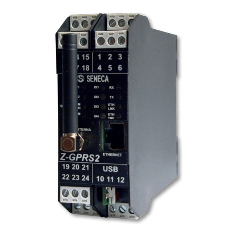
Seneca Z-LOGGER User manual

Page 1
MI003574_EN
SENECA s.r.l.
Via Austria 26, PADOVA –ITALY
Tel. +39.049.8705355 –8705359 Fax. +39.049.8706287
Web site: www.seneca.it
(Other)
(Other)
This document is property of SENECA srl. Duplication and reproduction of its are forbidden
(though partial), if not authorized. Contents of present documentation refers to products and
technologies described in it. Though we strive for reach perfection continually, all technical data
contained in this document may be modified or added due to technical and commercial needs;
it’s impossible eliminate mismatches and discordances completely. Contents of present
documentation is anyhow subjected to periodical revision. If you have any questions don’t
hesitate to contact our structure or to write us to e-mail addresses as above mentioned.
USER MANUAL
Z-GPRS2-SEAL
Z-LOGGER-SEAL
Z-GPRS2-SEAL
Multi-protocol Datalogger/RTU with GSM/GPRS modem and embedded I/O
Z-LOGGER
Multi-protocol Datalogger/RTU with embedded I/O

USER MANUAL –Z-GPRS2-SEAL / Z-LOGGER-SEAL
2
Date
Version
Changes
23/04/14
1
First Revision
15/05/14
2
Modified the remote firmware and configuration update
file names.
Added new SMS commands.
Added the Syslog “week rotation”.
Added chapters: Fw update, Configuration update and
Troubleshooting.
21/05/14
3
Changed chapters Local and remote firmware and
configuration update.
Added chapter Extended Phonebook
31/10/14
4
Changed update remote FW/CFG/PHONEBOOK chapters
Added Modbus TCP-IP Server commands
Changed USB drivers chapter (now are signed)
10/02/15
5
http post available only with a GPRS connection

USER MANUAL –Z-GPRS2-SEAL / Z-LOGGER-SEAL
3
SENECA Z-GPRS2 / Z-LOGGER .....................................................................................11
PRELIMINARY INFORMATION........................................................................................11
1. CHARACTERISTICS..................................................................................................13
1.1. Z-GPRS2 Model characteristics......................................................................................................................13
1.2. Z-LOGGER Model characteristics ...................................................................................................................14
1.3. Technical Specifications ................................................................................................................................14
1.4. Digital Inputs.................................................................................................................................................14
1.5. Digital outputs ..............................................................................................................................................15
1.6. Analog Inputs................................................................................................................................................15
1.7. Communication Ports....................................................................................................................................15
1.8. Storage units.................................................................................................................................................16
1.9. Power supply ................................................................................................................................................16
1.10. Environmental conditions .............................................................................................................................16
1.11. Regulations ...................................................................................................................................................16
1.12. Case specifications ........................................................................................................................................17
1.13. Insulation......................................................................................................................................................17
2. CONNECTIONS..........................................................................................................18
2.1. Power supply connections ............................................................................................................................18
2.2. Analog input connections..............................................................................................................................18
2.3. Auxiliary voltage connections .......................................................................................................................18

USER MANUAL –Z-GPRS2-SEAL / Z-LOGGER-SEAL
4
2.4. Serial communication RS485 ports connections ............................................................................................19
2.5. Digital outputs connections ..........................................................................................................................20
2.6. Digital inputs connections.............................................................................................................................20
3. SIGNAL LEDS............................................................................................................21
3.1. Z-GPRS2 leds .................................................................................................................................................21
3.2. Z-Logger leds.................................................................................................................................................22
4. DEVICES OVERVIEW................................................................................................24
5. SWITCH ON, SWITCH OFF AND FORCED SWITCH OFF OF Z-GPRS2/Z-LOGGER
25
6. SUPPORTED SIM CARDS (Z-GPRS2 ONLY)...........................................................26
7. GSM SIGNAL (Z-GPRS2 ONLY)................................................................................27
8. BACKUP BATTERY...................................................................................................29
9. USB DRIVER INSTALLATION ON MICROSOFT WINDOWS™ OPERATING
SYSTEMS..........................................................................................................................29
9.1. Installing the USB driver on Windows XP™, Windows Vista™ , Windows 7™, Windows 8™ and Windows
8.1™ 30
10. SEAL (SENECA ADVANCED LANGUAGE) ..........................................................30
10.1. SEAL Overview ..............................................................................................................................................31
10.2. Program Execution in the Graph Panel..........................................................................................................32
10.3. How SEAL works............................................................................................................................................32
11. THE SEAL MENU BAR...........................................................................................36
11.1. Menu File......................................................................................................................................................36
11.2. Menu Edit .....................................................................................................................................................36
11.3. Menu Project Project Settings.......................................................................................................................37
11.4. Groups, Profiles and Users ............................................................................................................................38

USER MANUAL –Z-GPRS2-SEAL / Z-LOGGER-SEAL
5
11.5. Menu Project: Users......................................................................................................................................44
11.6. Menu Project: User –Add User .....................................................................................................................45
11.7. Menu Project: User Groups...........................................................................................................................45
11.8. Menu RTU: Connection .................................................................................................................................46
11.9. Menu RTU Test Monitor................................................................................................................................47
11.10. Menu RTU: FW Update .............................................................................................................................52
11.11. Menu RTU: Open project from RTU ..........................................................................................................53
11.12. Menu RTU: Convert Phonebook CSV.........................................................................................................53
11.13. Menu Build: Generate...............................................................................................................................53
11.14. Menu Build: Generate and send to RTU....................................................................................................54
11.15. Menu Window: Build Output....................................................................................................................55
11.16. Menu Window: Edit Form .........................................................................................................................55
11.17. Menu Window: Logs .................................................................................................................................55
11.18. Menu Window: Default Layout.................................................................................................................56
11.19. Menu Window: Tile Horizontal .................................................................................................................56
11.20. Menu Window: Tile Vertical .....................................................................................................................56
11.21. Menu help ................................................................................................................................................56
12. THE SEAL ICON MENU..........................................................................................56
12.1. GSM/GPRS Modem.......................................................................................................................................57
12.2. Ethernet Services ..........................................................................................................................................59
12.3. Real Time Clock.............................................................................................................................................68
12.4. Cloud.............................................................................................................................................................72
12.5. Modbus RTU and Modbus TCP-IP Master Window .......................................................................................76
12.6. Data Logger Window.....................................................................................................................................84
12.7. Application Window .....................................................................................................................................89
12.8. System Management Configuration Window................................................................................................98
USER MANUAL –Z-GPRS2-SEAL / Z-LOGGER-SEAL
6
12.9. Analog Input Configuration Window.............................................................................................................99
12.10. Digital Input Configuration Window .......................................................................................................102
12.11. Digital Input Configuration Window .......................................................................................................103
12.12. Digital Output Configuration Window.....................................................................................................107
13. EVENT BLOCKS...................................................................................................108
13.1. Event Block SYS_POW_DOWN: System Management Power Down............................................................108
13.2. Event Block SYS_LOW_BAT: System Management Battery Control.............................................................109
13.3. Event Block AIN_MAX: Analog Input Maximum Threshold Event................................................................109
13.4. Event Block AIN_HIGH: Analog Input High Threshold Event ........................................................................109
13.5. Event Block AIN_LOW: Analog Input Low Threshold Event .........................................................................109
13.6. Event Block AIN_LOW: Analog Input Low Threshold Event .........................................................................110
13.7. Event Block RTC_DAYLIGHT: Daylight Event ................................................................................................110
13.8. Event Block RTC_DAWN: Sunrise Event.......................................................................................................110
13.9. Event Block RTC_DUSK: Sunset Event..........................................................................................................110
13.10. Event Block RTC_SYNC: Time Synchronization Error Event......................................................................111
13.11. Event Block DIN_ON: Not filtered Digital Input ON Event .......................................................................111
13.12. Event Block DIN_ALM: Filtered Digital Input Event .................................................................................111
13.13. Event Block DIN_TOT_ALM: Total Counter Event ....................................................................................111
13.14. Event Block DIN_CNT_ALM: Partial Counter Event..................................................................................112
13.15. Event Block DIN_WORK_ALM: Work Time Event ....................................................................................112
13.16. Event Block DIN_DELTA_ALM: Delta Counter Event................................................................................112
13.17. Event Block DIN_TOT_RESET: Total Counter Reset Event ........................................................................112
13.18. Event Block DIN_CNT_RESET: Partial Counter Reset Event......................................................................113
14. VARIABLE BLOCKS.............................................................................................113
14.1. Variable Block SYS_POW: Main Power Variable..........................................................................................113
14.2. Variable Block SYS_VBAT: Main Power Variable .........................................................................................113

USER MANUAL –Z-GPRS2-SEAL / Z-LOGGER-SEAL
7
14.3. Variable Block AIN_VAL : Analog Input Datalogger Sampled Value .............................................................114
14.4. Variable Block AIN_AVG : Analog Input Datalogger Average Value .............................................................114
14.5. Variable Block AIN_MIN : Analog Input Datalogger Minimum Value...........................................................114
14.6. Variable Block AIN_MAX : Analog Input Datalogger Maximum Value .........................................................115
14.7. Variable Block DIN_STS: Digital Input Value Sampled Variable ...................................................................115
14.8. Variable Block DIN_TOT: Total Counter Value Sampled Variable ................................................................116
14.9. Variable Block DIN_CNT: Partial Counter Value Sampled Variable ..............................................................116
14.10. Variable Block DOUT_STS: Digital Output Value Sampled Variable .........................................................116
14.11. Variable Block GSM_DBM: GSM signal field Value Sampled Variable .....................................................117
14.12. Variable Block MODBUS IN/OUT: Modbus Value Variable......................................................................117
15. BLOCKS FUNCTIONS..........................................................................................118
15.1. Function Block BIT: STATE BITS TEST FUNCTION..........................................................................................118
15.2. Function Block BIT_AND: AND REGISTERS STATE BITS TEST FUNCTION .......................................................119
15.3. Function Block BIT_AND: OR REGISTERS STATE BITS TEST FUNCTION .........................................................121
15.4. Function Block CMP: ANALOG DIFFERENCE COMPARE FUNCTION ..............................................................122
15.5. Function Block THR: ANALOG THRESHOLD COMPARE WITH HYSTERESIS FUNCTION ..................................123
15.6. Function Block CPY: ANALOG VARIABLE COPY TO ANOTHER VARIABLE WITH TRIGGER FUNCTION ............124
15.7. Function Block LST: SCALED ANALOG INPUTS LESS THAN COMPARE FUNCTION .........................................125
15.8. Function Block GRT: SCALED ANALOG INPUTS GREATER THAN COMPARE FUNCTION.................................126
15.9. Function Block POW: ANALOG INPUTS MULTIPLICATION GREATER THAN COMPARE FUNCTION................127
15.10. Function Block AVG: ANALOG AVERAGE GREATER THAN COMPARE FUNCTION .....................................128
15.11. Function Block DEV: ANALOG AVERAGE ABSOLUTE DIFFERENCE GREATER THAN COMPARE FUNCTION 129
15.12. Function Block MAD: ANALOG AVERAGE ABSOLUTE DIFFERENCE COMPARE WITH CHANNEL DETECT
FUNCTION130
16. BLOCKS CONTROLS...........................................................................................132
16.1. Control Block EC: EVENT LOGIC CONTROL ...................................................................................................132

USER MANUAL –Z-GPRS2-SEAL / Z-LOGGER-SEAL
8
16.2. Control Block EC setup configuration ..........................................................................................................135
16.3. Control Block MSG: Event notify Message...................................................................................................138
16.4. Control Block CAL: Calendar Block Control ..................................................................................................139
16.5. Control Block TRG: Timed Trigger Block Control..........................................................................................141
16.6. Control Block TMR: Timer Control Block Control.........................................................................................143
17. BLOCKS ACTIONS DOUTS.................................................................................146
17.1. Action Block DOUTS RESET: Reset digitals output 1 and output 2 action.....................................................146
17.2. Action Block DOUTS SET: Set digitals output 1 and output 2 action ............................................................147
17.3. Action Block DOUTS TOGGLE: Toggle digitals output 1 and output 2 action................................................147
17.4. Action Block DOUTS RES1_SET2: Reset digital output 1 and Set digital output 2 action ..............................148
17.5. Action Block DOUTS SET1_RES2: Set digital output 1 and Reset digital output 2 action ..............................148
17.6. Action Block DOUT RESET: Reset digital output action ................................................................................149
17.7. Action Block DOUT SET: Set digital output action........................................................................................149
17.8. Action Block DOUT TOGGLE: Toggle digital output action ...........................................................................150
17.9. Action Block PULSE_RESET: Pulse Reset output action ................................................................................150
17.10. Action Block PULSE_SET: Pulse Set output action ...................................................................................151
17.11. Action Block PULSE_TOGGLE: Pulse Toggle output action .......................................................................151
18. BLOCKS ACTIONS MODBUS..............................................................................152
18.1. Action Block BIT_CLR: Modbus Register Bit Clear action .............................................................................152
18.2. Action Block BIT_SET: Modbus Register Bit Set action.................................................................................152
18.3. Action Block DEC: Modbus Register Decrement Action ...............................................................................153
18.4. Action Block INC: Modbus Register Increment Action .................................................................................153
18.5. Action Block RES: Modbus Register Reset Action ........................................................................................154
18.6. Action Block COPY: Modbus Register Copy Action ......................................................................................154
19. LOCAL FIRMWARE UPDATE ..............................................................................154

USER MANUAL –Z-GPRS2-SEAL / Z-LOGGER-SEAL
9
19.1. Firmware update via USB............................................................................................................................155
19.2. Firmware update via microSD card (without using a PC).............................................................................155
20. REMOTE FIRMWARE UPDATE ...........................................................................156
20.1. Remote firmware update by Ethernet connection (FTP Server activated) ...................................................156
20.2. Remote firmware update by Ethernet connection (Modbus TCP-IP Server activated).................................156
20.3. Remote firmware update by GPRS connection............................................................................................157
21. LOCAL CONFIGURATION UPDATE....................................................................159
21.1. Local configuration update by SD card ........................................................................................................159
22. REMOTE CONFIGURATION UPDATE.................................................................159
22.1. Remote configuration update by Ethernet connection (FTP Server enabled) ..............................................159
22.2. Remote configuration update by Ethernet connection (Modbus TCP-IP Server enabled) ............................160
22.3. Remote configuration update by GPRS connection .....................................................................................161
23. EXTENDED PHONEBOOK INTO MICROSD FOR RING COMMAND.................162
23.1. Creation of an Extended Phonebook File ....................................................................................................162
23.2. Update of an Extended Phonebook File Via Ethernet..................................................................................163
23.3. Update of an Extended Phonebook File Via Gprs ........................................................................................163
24. SUPPORTED SMS COMMANDS (ONLY Z-GPRS2)............................................163
24.1. Set the Telephone Sms Character Alphabet ................................................................................................163
24.2. List of Supported Sms Commands ...............................................................................................................164
25. SUPPORTED MODBUS TCP-IP COMMANDS (ONLY BY ETHERNET).............169
26. SEAL PROGRAM EXAMPLES.............................................................................170
26.1. Send Alert SMS on digital input 1 and copy alert state on output 1 ............................................................170
26.2. Temperature Control with Logger and Alerts ..............................................................................................172
26.3. Remote inputs to remote outputs copy by ethernet connection.................................................................174

USER MANUAL –Z-GPRS2-SEAL / Z-LOGGER-SEAL
11
Seneca Z-GPRS2 / Z-LOGGER
PRELIMINARY INFORMATION
CAUTION!
Contact your telephone provider for information on GSM and GPRS service costs. It is best to
quantify log and SMS costs before setting up and installing Z-GPRS2.
The use of Z-GPRS2 in data roaming (for example, abroad with an Italian SIM card) may
generate unexpected costs. Contact your telephone provider for further information.
IN NO CASE MAY SENECA OR ITS SUPPLIERS BE HELD LIABLE FOR ANY INCOMING DATA OR
PROFIT LOSSES DUE TO INDIRECT, CONSEQUENTIAL OR INCIDENTAL CAUSES (INCLUDING
NEGLIGENCE) CONNECTED WITH THE USE OR INABILITY TO USE Z-GPRS2 AND Z-LOGGER, EVEN IF
SENECA WAS INFORMED OF THE POTENTIAL OF THESE DAMAGES.
SENECA, ITS SUBSIDIARIES OR AFFILIATES OR GROUP PARTNERS OR DISTRIBUTORS AND SENECA
DEALERS DO NOT GUARANTEE THAT THE FUNCTIONS FAITHFULLY MEET THE EXPECTATIONS AND
THAT Z-GPRS2 AND/OR Z-LOGGER, THEIR FIRMWARE AND SOFTWARE ARE FREE OF ERRORS OR
FUNCTION UNINTERRUPTEDLY.
SENECA HAS TAKEN THE UTMOST CARE AND CAUTION IN DRAFTING THIS MANUAL. HOWEVER,
IT MAY CONTAIN ERRORS OR OMISSIONS. SENECA SRL RESERVES THE RIGHT TO MODIFY
AND/OR VARY PARTS OF THIS MANUAL TO CORRECT ERRORS OR TO ADJUST TO PRODUCT
FEATURE CHANGES WITHOUT ANY PRIOR NOTICE.
CAUTION!
-Contact your telephone service provider for GSM and GPRS service costs especially when using
Z-GPRS2 with a sim issued by a country other than the one in which it is used (international
roaming).
-It is best to estimate telephone costs before setting up Z-GPRS2.
-The cost of each SMS is set by the telephone service provider.
-GPRS send/receive costs can be tied to Kbytes sent/received, a monthly ceiling included in a
package or GPRS connection time. Contact your telephone service provider for further
information.

USER MANUAL –Z-GPRS2-SEAL / Z-LOGGER-SEAL
12
-For GPRS connections whose costs is associated with connection time, please remember that
communications are active for an amount of time that depends on the number of log rows to be
sent. Typically, a 2 Kbyte data log takes about 10-15 seconds to be sent in addition to the time
necessary to establish the connection (from 5 to 30 seconds) and the time due to any server login
attempts.
-Check the data quantity sent via GPRS and SMS before using Z-GPRS2.
Please remember that mobile phone service providers also consider the entire communication
that permits file transmission (and thus data transmission overhead, the number of connection
attempts, etc.) and not just the dimensions as data traffic in each GPRS transaction.

USER MANUAL –Z-GPRS2-SEAL / Z-LOGGER-SEAL
13
1. CHARACTERISTICS
1.1. Z-GPRS2 Model characteristics
Z-GPRS2 is a multi-protocol programmable datalogger/RTU with GSM/GPRS modem and
embedded IO.
Supply voltage 11..40 Vdc; 19..28 Vac max 6.5 W
2 AAA 1.2 V, NiMh rechargeable backup batteries
GSM/GPRS Quad-Band modem
500 Vac insulation between remaining circuit power
Quick installation on DIN 46277 guide
Status indication LED: digital inputs, digital outputs, Ethernet, GSM, RS485, Power,
microSD
NR 4 digital inputs
NR 2 16-bit voltage/current programmable analog inputs
NR 2 relay digital outputs
10/100 Mbps frontal Ethernet RJ45
NR 2 RS484 ports
1 type B miniUSB port for settings
MicroSD support (microSD or microSDHC max 32 Gb)
NR4 32 bits max 30 Hz totalizers
NR4 32 bits max 30 Hz resettable counters
Possibility of expanding the number of I/O via Modbus TCP-IP or Modbus RTU
Maximum number of channels on datalogger: 128 (of which 100 via Modbus RTU/TCP-IP)
Supported system protocols via GSM: SMS, voice calls (zero cost command)
Supported system protocols via GPRS: FTP client, SMTP client, SMTPS client
Supported system protocols via Ethernet port: FTP client, FTP server*, SMTP client,
ModBUS TCP-IP Server
Protocol on RS485: Modbus RTU Master
Webserver* via Ethernet port
128 KB RAM memory
Memory expansion up to 32 GigaBytes with micro SD
32 bits ARM processor
Real Time multitasking operating system
Firmware update via USB / microSD/or by remote connection
*= Ethernet services cannot be used simultaneously

USER MANUAL –Z-GPRS2-SEAL / Z-LOGGER-SEAL
14
1.2. Z-LOGGER Model characteristics
Z-LOGGER is a multi-protocol programmable datalogger/RTU with embedded IO.
Supply voltage 11..40 Vdc; 19..28 Vac max 6.5 W
NR 2 AAA 1.2 V, NiMh rechargeable backup batteries
500 Vac insulation between remaining circuit power
Quick installation on DIN 46277 guide
Status indication LED: digital inputs, digital outputs, Ethernet, RS485, Power, microSD
NR 4 digital inputs
NR 2 16-bit voltage/current programmable analog inputs
NR 2 clean contact relay digital outputs
10/100 Mbps frontal Ethernet RJ45
NR 2 RS484 ports
1 type B miniUSB port for settings
MicroSD support (microSD or microSDHC max 32 Gb)
NR4 32 bits max 30 Hz totalizers
NR4 32 bits max 30 Hz resettable counters
Possibility of expanding the number of digital or analog I/O via Modbus TCP-IP or
Modbus RTU
Maximum number of channels on datalogger: 128 (of which 100 via Modbus RTU/TCP-IP)
Supported system protocols via Ethernet port: FTP client, FTP server*, SMTP client,
ModBUS TCP-IP Server
System protocol on RS485: Modbus RTU Master
Webserver* via Ethernet port
128 KB RAM memory
Memory expansion up to 32 GB with micro SD
32 bits ARM processor
Real Time multitasking operating system
Firmware update via USB / microSD or by remote connection
*= Ethernet services cannot be used simultaneously
1.3. Technical Specifications
1.4. Digital Inputs
Channels number
4

USER MANUAL –Z-GPRS2-SEAL / Z-LOGGER-SEAL
15
Input type
PNP, NPN configurable.
Voltage supply
12 Vdc
Current supply
20 mA
Maximum frequency
30 Hz
Current consumption
3 mA
1.5. Digital outputs
Channels number
2
Output type
Relay
Maximum Voltage
250 Vac
Maximum Current
2 A
1.6. Analog Inputs
Channels number
2
Input type
Current / Voltage configurable
Voltage input
0..30V accuracy 0,1% FS
Current input
0..20 mA accuracy 0,1% FS
Input protection
yes, 12Vdc or 25mA
Resolution
16 bits
1.7. Communication Ports

USER MANUAL –Z-GPRS2-SEAL / Z-LOGGER-SEAL
16
RS 485 #1
Port #1, on IDC10 connector
RS 485 #2
Port #2, terminals M10/M11/M12
Ethernet
10/100 Mbit, RJ45 with autoswitch
USB mini B
Mini B
1.8. Storage units
Internal Flash
2 Mbytes for configuration and for logger
Buffer
MicroSD
microSD and microSDHC, max 32 GB
(supplied with 1, 2 or 4GBytes microSD)
1.9. Power supply
Voltage
11...40 Vdc; 19…28 Vac
Power consumption
6,5 W
1.10. Environmental conditions
Temperature
From -10 to +40 °C
Humidity
30..90% to 40 °C non condensing
Storage temperature
From -20 to +45 °C < 6 months
Protection rating
IP20
1.11. Regulations

USER MANUAL –Z-GPRS2-SEAL / Z-LOGGER-SEAL
17
EN61000-6-4/2002-10
Electromagnetic emission, industrial
environment.
EN61000-6-2/2006-10
Electromagnetic immunity, industrial
environment.
EN 301 511 (only Z-GPRS2)
Harmonized standard for mobile stations in the
GSM
900 and 1800 bands.
EN 301 489-1 (only Z-GPRS2)
ElectroMagnetic Compatibility standard for
radio equipment and services.
EN 301 489-7 (only Z-GPRS2)
Specific (EMC) conditions for mobile radio
equipment
(GSM 900 and 1800).
EN 60950
Safety of information Technology Equipment.
1.12. Case specifications
Dimensions and weight
100 x 111 x 35 mm, 280 g
Material
Black PBT
1.13. Insulation
500 Vac

USER MANUAL –Z-GPRS2-SEAL / Z-LOGGER-SEAL
18
2. CONNECTIONS
2.1. Power supply connections
You can supply DC or AC power to terminals 2-3, in the case of DC power supply is not necessary to
distinguish between the "+" from the "-" cable:
2.2. Analog input connections
The analog input 1 voltage / current is connected to terminal 4 (- sign for the voltage, the current exit) and
6 (+ sign to the voltage, the current incoming).
The analog input 2 voltage / current is connected to terminal 4 (- sign for the voltage, the current exit) and
5 (+ sign to the voltage, the current incoming).
2.3. Auxiliary voltage connections
The device can provide from 12 to 15 VDC (max 40mA) to an external sensor connected to terminals 1 (+)
and 4 (-):

USER MANUAL –Z-GPRS2-SEAL / Z-LOGGER-SEAL
19
2.4. Serial communication RS485 ports connections
The RS485 port # 1 is connected to the bottom connector "IDC10" for connecting to the Z-BUS Seneca.
WARNING!
In order to use the Z-BUS connector RS485 as you need to move SW2 to "rear IDC10 connector is
485":
SW2 ■= ON
Rear IDC10 connector, CANopen (not supported)
■
Rear IDC10 connector, RS485
The RS485 #2 port is connected to terminal 10-11-12:
10 = GND RS485#2
11 = A RS485#2
12 = B RS485#2

USER MANUAL –Z-GPRS2-SEAL / Z-LOGGER-SEAL
20
2.5. Digital outputs connections
The output relay is connected between terminals 19-20-21:
19 = Normally open relay #1
21 = Shared relay #1
22 = Normally close relay #1
22 = Normally open relay #2
23 = Shared relay #2
24 = Normally close relay #2
2.6. Digital inputs connections
It’s possible to provide power to an external sensor by terminals 15-16 (max 40mA) .
The inputs can be configured in NPN or PNP mode, see below:
This manual suits for next models
2
Table of contents
Other Seneca Data Logger manuals

Seneca
Seneca Z-GPRS2 User manual

Seneca
Seneca Z-LTE User manual

Seneca
Seneca Z-UMTS User manual

Seneca
Seneca MyALARM2 User manual

Seneca
Seneca RTU-LP User manual

Seneca
Seneca MyAlarm SEAL User manual

Seneca
Seneca Z-LOGGER3 User manual

Seneca
Seneca Z-UMTS HW2 User manual

Seneca
Seneca Z-8R-10A User manual

Seneca
Seneca MyALARM2 User manual
Popular Data Logger manuals by other brands

Measurement Computing
Measurement Computing USB-2416-4AO user guide

Dynastream Innovations
Dynastream Innovations AMP 331 Instruction for users

Dostmann Electronic
Dostmann Electronic LOG40 operating instructions

Decagon Devices
Decagon Devices EM50G manual

Escort
Escort MU-IN-D-8-L user guide

Mace
Mace HydroMace XCi product manual