Delta OHM HD37B17D User manual

Operating manual
Data logger
Temperature – RH – CO – CO2
HD37AB17D – HD37B17D
www.deltaohm.com
Companies / Brands of GHM
English
Keep for future reference.

HD37AB17D/HD37B17D - 2 - V1.5
Datalogger RH – Temperature – CO – CO2
HD37AB17D and HD37B17D
1
2
3
5
4
6
7

HD37AB17D/HD37B17D - 3 - V1.5
HD37AB17D – HD37B17D
1. Humidity and temperature sensor.
2. Wicket through which you can enter to the CO sensor (Carbon Monoxide) (only
HD37AB17D).
3. It visualizes the working state of the instrument.
4. It offers the information about the charge state of the Ni-MH rechargeable bat-
teries.
5. Button ON/OFF: it switches the instrument ON and OFF.
6. Connector for the inlet of the external power supply (6 Vdc – 1A). The positive
pole is the central one
7. USB 2.0 type B connector for the connection to the PC.

HD37AB17D/HD37B17D - 4 - V1.5
INDEX
1 . INTRODUCTION...................................................................................... 5
2 . KEYBOARD AND LED DESCRIPTION......................................................... 6
3 . INSTRUMENT INSTALLATION.................................................................. 7
3.1 . POWER SUPPLY ....................................................................................7
3.1.1 . Batteries recharge...........................................................................8
3.1.2 . Notes for the batteries use................................................................8
3.1.3 . Replacement of the batteries package ................................................9
3.1.4 . Batteries disposal............................................................................9
3.2 . CONNECTION TO THE PC ..................................................................... 10
3.2.1 Serial commands ............................................................................ 10
4 . SENSORS CALIBRATION ........................................................................12
4.1 . RH SENSOR CALIBRATION ................................................................... 12
4.2 . CO SENSOR CALIBRATION (ONLY HD37AB17D) ....................................... 13
4.3 . CO2SENSOR CALIBRATION .................................................................. 15
5 . TECHNICAL FEATURES ...........................................................................16
6 . STORAGE...............................................................................................17
7 . ORDER CODES .......................................................................................18

HD37AB17D/HD37B17D - 5 - V1.5
1. INTRODUCTION
HD37AB17D and HD37B17D instruments are dataloggers able to simultaneously
measure and memorize the following parameters:
•Relative Humidity RH
•Ambient temperature T
•Carbon Monoxide CO (only HD37AB17D)
•Carbon dioxide CO2
HD37AB17D and HD37B17D are instruments suitable to research and monitor the
air quality in internal environments.
Typical applications are the examination of the air quality in all the buildings where
there is a crowd of people (schools, hospitals, auditoria, canteens, etc.), in the work
environments in order to optimize the comfort and in the buildings in order to check if
there is a small emission of CO, with the risk of explosions or fires. This analysis al-
lows setting the air-conditioning unit (temperature and humidity) and ventilation (air
replacement/hour) in order to get a double purpose: getting a good quality of the air
according to ASHRAE and IMC regulations in force and an energetic saving.
HD37AB17D and HD37B17D are instruments suitable to fight the so-called syn-
drome of the ill building.
RH measurement (Relative Humidity) is obtained with a sensor of capacitive type.
T temperature is measured with a high-precision sensor of NTC type.
The sensor for CO (Carbon Monoxide, only HD37AB17D) measurement consists of
an electrochemical cell with two electrodes suitable to detect the presence of carbon
monoxide, lethal for man, in residential and industrial environments.
CO2 (Carbon Dioxide) measurement is obtained with the special infrared sensor
(NDIR technology: Non-Dispersive Infrared Technology) that, thanks to the use of a
double filter and a special measurement technology, warranties precise and constant
measurements over the time. The presence of a protection membrane through which
is given off the air to check, protects the sensor from dust and atmospheric agents.
HD37AB17D and HD37B17D are dataloggers able to memorize the detected
measurements, with a frequency prearranged by the user.
HD37AB17D and HD37B17D connect to the PC through USB inlet.
The instruments are supplied with DeltaLog13 Software with which you can manage
the connection operations to the PC, the RH, CO (only HD37B17D) and CO2 sensor
calibrations, the instrument working parameters setup, the data transfer, the graphi-
cal introduction and the acquired or memorized measurements print.
Through an appropriate procedure, the Software DeltaLog13 can evaluate the pa-
rameter % OA (percentage of external air), according to the formula:
100% ⋅
−
−
=
or
sr
XX
XX
OA
whereas:
Xr = CO2 in return air
Xs= CO2 in the outlet air
X0= CO2 in the external air

HD37AB17D/HD37B17D - 6 - V1.5
The power supply of the instrument is provided with a 2 Ni-MH rechargeable batteries
package (code BAT-20), that ensures over 8 hours of continuous working, in acquisi-
tion mode.
2. KEYBOARD AND LED DESCRIPTION
The instrument can have two working modes: the stand-by mode (signalled, every 5
seconds, by a short flashing of the led activity) in which the instrument is waiting to
be commanded and reduces the battery consumption to the minimum, and the
measurement mode (signalled, every 3 seconds, by a double long flashing of the
activity led) in which the instrument simultaneously measures all the parameters (RH,
T, CO, CO2) and memorizes them in its own internal memory with the set memoriza-
tion frequency. From stand-by mode you can always pass to the measurement
mode, pushing the button ON/OFF.
When it is connected to the PC, the instrument automatically goes in measurement
modality.
Button ON/OFF
To switch the instrument on (measurement mode) press the button ON/OFF till the
Led Activity starts emitting two long and close flashings, so release the button.
To switch the instrument off (stand-by mode) press the button ON/OFF till the Led
Activity starts emitting two long and close flashings, so release the button.
It’s not possible to switch the instrument off when it’s connected to the PC.
Led CHARGE
The led CHARGE offers the information about the charge state of Ni-MH rechargeable
batteries.
When the external power supply is connected, the instrument checks the rechargeable
batteries charge state and, if necessary, starts the charge operation.
The real charge can be preceded by a pre-charge phase; an inserted mode in order to
avoid exorbitant stresses of the batteries when they are particularly discharged or
their temperature is too low: in this phase the led CHARGE emits a flashing per sec-
ond.
After this first phase, the quick charge starts: The led CHARGE remains fixedly ON and
it switches OFF only if the charge is completed.
Now it’s possible to disconnect the external power supply and use the instrument us-
ing only rechargeable batteries.
Led ACTIVITY
The led ACTIVITY visualizes the working state of the instrument. Every 5 seconds, a
short flashing indicates the stand-by mode. At least every 3 seconds, a double flash-
ing indicates that the instrument is measuring.

HD37AB17D/HD37B17D - 7 - V1.5
3. INSTRUMENT INSTALLATION
The instrument has an inlet for the power supply and the recharge of the internal bat-
teries and a 2.0 USB output B type for the connection to the PC.
3.1. POWER SUPPLY
The instrument has an inlet (1) for the external power supply (6 Vdc – 1A) code
SWD06. The power supply has a double function: it feeds the instrument and re-
charges the Ni-MH batteries package.
Power supply connector
The power supply connector has a 5.5mm external diameter and a 2.1mm internal
diameter.
The positive pole is the central one:
The power supply provided with the instrument has SWD06 code and the following
features:
•Exit voltage: 6Vdc
•Maximum current: 1600mA (9,60 VA Max).
The instrument is provided with a package of 2 Ni-MH rechargeable batteries at 1.2V–
2200mA/h, placed in the battery case.
To recharge the batteries, follow the following instruction.
1

HD37AB17D/HD37B17D - 8 - V1.5
3.1.1. Batteries recharge
To recharge the batteries package, use the SWD06 battery charger provided with the
instrument.
Go on as indicated below:
•connect the pin of the battery charger to the power supply net and the connector
of the battery charger to the pin placed at the left of the instrument. The power
supply must be 6Vdc.
•If the batteries are particularly discharged or their temperature is about zero, the
led CHARGE flashes for some seconds (pre-charge phase) and then it remains fix-
edly on in order to indicate that the instrument is in the speed charge phase.
•Charge the batteries till the led CHARGE doesn't switch off.
3.1.2. Notes for the batteries use
•At the first start up, it’s necessary to completely recharge the batteries.
•The charge time of the batteries package is about 4 hours.
•The last of the batteries package in measurement working mode is about 8 hours.
•A new Ni-MH batteries package reaches the maximum of its performance only after
being discharged and charged completely again at least twice or three times.
•The batteries package autonomy depends on the instrument use. Even if the in-
strument is in stand-by with the batteries package completely charges, it is
autonomously charged during the time.
•The batteries package can be charge and discharge hundred of times, but using
them the charge loses its own capacity. Replace the batteries package when the
autonomy is reduced at some hours.
•Use only Delta Ohm batteries package code BAT-20 and recharge it using SWD06
battery charger or one that complies with the specifications indicated in the techni-
cal data.
•The Ni-MH batteries package lasts more if, sometimes, you act with cutting and
you completely discharge it.
•Extreme temperatures weigh negatively on the performances of the batteries
package.
•At the beginning of a new charge, you can check a variation of the internal tem-
perature of the instrument that can temporarily influence the CO2 measurement.

HD37AB17D/HD37B17D - 9 - V1.5
3.1.3. Replacement of the batteries package
For the replacement of the batteries package, go on as indicated below:
•Disconnect the external power supply, if connected.
•Remove, from the back of the instrument, the lid of the batteries case placed on
the bottom of the instrument unfastening the screw (1).
•Take off the connector, paying attention not to tear the wires away.
•Remove the batteries package.
•Connect the connector to the new batteries package: the connector has a refer-
ence that prevents a wrong insertion.
•Place the package in the batteries case.
•Close the batteries case again with the clamping screw.
3.1.4. Batteries disposal
Recycle the batteries or throw them in a suitable manner.
Don’t throw the batteries to the waste.
Don’t throw the batteries into the fire.
1

HD37AB17D/HD37B17D - 10 - V1.5
3.2. CONNECTION TO THE PC
The instrument is provided with a 2.0 USB communication interface B type. For the
connection to the PC, it’s required the cable code CP22.
The instruments are supplied with DeltaLog13 software. With the software you can
manage the connection operations to the PC, the CO2sensor calibration (only
HD37B17D), the RH calibrations, the instrument working parameters setup, the data
transfer, the graphical introduction, the acquired or memorized measurements print.
DeltaLog13 software is endowed with a “Help on-line” (also in pdf format) that
describes the features and the functions.
Moreover, the instruments are compatible with HyperTerminal communication pro-
gram supplied together with Windows operational systems (from Windows 98 to Win-
dows XP).
3.2.1 Serial commands
The connection through USB requires the prior installation of a driver inserted into the
DeltaLog13 software CD-ROM. Before connecting the USB cable to the PC, in-
stall the driver (please see the documentation provided with DeltaLog13 CD-
ROM).
The parameters of the instrument USB serial transmission are:
•Baud rate 480600 baud
•Parity None
•Bit number 8
•Bit stop 1
•Protocol Xon / Xoff.
The instruments are provided with a full kit of controls and request of data sent by the
PC.
All the controls sent to the instrument must have the following structure:
A00ZXXCR where: XX is the control code and CR is the Carriage Return (code
ASCII 0D).
The XX control characters are only capitals, the instrument responses with “&” if the
key is right, with “?” if any combination of characters is wrong.
The response strings of the instrument finish with “|” character (code ASCII 124) fol-
lowed by the enter of the keys (Carriage Return) and LF (Line Feed).
Key Response Description
A00ZP0 &| Ping
A00ZS0
A00ZS1
A00ZS2
A00ZDAaammgghhmmss
A00ZDSaammgghhmmss
A00ZDLxxxxx
A00ZFA
A00ZFS
A00ZG0 & HD37AB17D | Instrument code
A00ZG1 & V1R1 2008/12/05| Version and date of the Firmware

HD37AB17D/HD37B17D - 11 - V1.5
Key Response Description
A00ZG2 &2008/12/10 08.30.00 ;
2008/12/10 08.50.00 |
Date and hour of factory calibra-
tion
Date and hour of user calibration
A00ZG3 &12345678| Instrument serial number
A00ZG4 &USERCODE| User code (max. 32 characters)
A00ZK1 &| Start Logging
A00ZK0 &| Stop Logging
A00ZKT &| It enables the compensation in
temperature
A00ZKN It disables the compensation in
temperature
A00ZKRxxxx yyyy
It executes the memory Dump from
the xxxx page to the yyyy page
(pages: from 0000 to 1999)
A00ZKS It prints the list of the memo-
rized sections
A00ZKE &| It resets the number of the sec-
tions and of the records
A00ZKZ &| It resets the Flag of Automatic
Start
A00ZRL &00000| Length in seconds of the pro-
grammed Log
A00ZRM &06800| Next record number in logging
A00ZRP &01013| Set atmospheric pressure
A00ZRS &00 ; 00 ; FF ; 00 |
Options status:
FIRST BYTE:
temperature correction:
SECOND BYTE:
user correction: 00=off
THIRD BYTE:
Status Log: FF=off 00=start
01=Log 02=end
FOURTH BYTE:
Deferred Log: 00=off
A00ZRT &0000000090| Sections number
A00ZYU USER UN_locked|
It enables the user parameters
change
A00ZWUxx…x &|
It writes till 32 characters in
the user code (it’s accepted
only if it is preceded by
A00ZYU)
A00ZWAxx &|
It sets the average per package
on xx samples (from 3 sec to 60
sec)
A00ZWPxxxx &|0ZWP1013 Setup of atmospheric pressure

HD37AB17D/HD37B17D - 12 - V1.5
4. SENSORS CALIBRATION
The instruments are calibrated by the company and don’t usually request any other
intervention by the user. However, there is the possibility to calibrate again.
It’s possible to calibrate the RH (Relative Humidity), CO (Carbon Monoxide – only
HD37AB17D) and CO2(Carbon Dioxide) sensors.
It’s not foreseen any calibration for the temperature sensor.
To calibrate, it’s necessary to connect the instrument to the PC and start DeltaLog13
program.
For a right calibration of the probes, it’s important to know and respect the physical
phenomena that are at the basis of the measurement: For this reason, we suggest
you to carefully follow what is indicated below and calibrate again only if you have the
adequate technical knowledge:
4.1. RH SENSOR CALIBRATION
Before starting the calibration, it’s convenient to check, with the help of saturated so-
lutions at 75.4%RH and 33%U, the necessity to calibrate again: only if there is a
measurement mistake in at least one of these two points, go on calibrating.
This calibration process cancels the data of the previous calibrations.
For a correct sensor calibration, the first point must be at 75%RH and the second
one at 33%RH.
1. Connect the instrument to the PC by USB connection cable code CP22 and start
DeltaLog13 program. Follow the DeltaLog13 sensors calibration guided process.
2. Control that inside the chamber containing saturated saline solution, there are in
the same time:
•salt at solid state
•liquid solution or wet salt.
3. The instrument and the saturated solution to use for this operation must have the
same temperature and so they have to be placed in an environment with a stable
temperature for the whole period of the calibration.
4. Unscrew the protection grid of the probe, screw M12X1 ring nut of the plug of the
saturated solution.
5. If inside the measurement chamber some liquid is formed, dry it with an absorbent
clean sheet.
6. Screw the ring nut to the case with the saturated solution to check. Avoid any con-
tact of the sensible element with the hands or another item or liquids.
7. Once introduced the sensor, wait at least 30 minutes, if the probe and the salts
have the same temperature.
8. Follow the DeltaLog13 guided process for calibrating the sensor.

HD37AB17D/HD37B17D - 13 - V1.5
4.2. CO SENSOR CALIBRATION (ONLY HD37AB17D)
It’s possible to calibrate the CO sensor zero in clean air (in an external environment
the CO concentration is less than 0,1ppm) or using nitrogen cylinders (code MINI-
CAN.12A).
CO zero calibration in clean air:
1. Put the instrument in an environment with clean air (the concentration of CO in
the external environment is less than 0.1ppm), switch the instrument on and
wait at least 15 minutes because the measurement must stabilize.
2. Connect the instrument to the PC by USB connection cable code CP22 and start
DeltaLog13 program, so follow the instruction connected with the CO zero cali-
bration.
CO zero calibration with nitrogen cylinder (code MINICAN.12A):
1. Using a screwdriver, open the wicket on the frontal side of the instrument.
2. Connect the pipe coming from the MINICAN.12A cylinder with the rubber cowl-
ing on the CO sensor head.
3. Connect the instrument to the PC by the USB connection cable code CP22 to
the PC and start the DeltaLog13 guided process of sensors calibration.

HD37AB17D/HD37B17D - 14 - V1.5
4. Switch the instrument on and wait at least 15 minutes before proceeding.
5. Supply the gas, controlling the cylinder fluxmeter in order to have a constant
flow between 0.1 and 0.2 l/min.
6. Wait two minutes necessary for the calibration without modifying the working
conditions.
7. At the end of the process, close the cylinder tap and remove the CO sensor
cowling.
8. Insert the protection grid.
CO sensor replacement:
If it is necessary to replace the CO sensor, proceed as follows.
1. Switch the instrument off.
2. Using the screwdriver, open the wicket of the sensor-holder and pull the flat CO
sensor out.
3. Take the new CO sensor and note the number stamped on the new sensor bor-
der that expresses its own sensitivity in nA/ppm.
4. Insert the electrodes into the contact of the new sensor.
5. Switch the instrument on and wait at least 5 minutes till the measurement is
stabilized.
6. Connect the instrument to the PC by USB connection cable code and start Del-
taLog13 program, go to replace CO sensor.
If necessary, execute the zero calibration of the new CO sensor.

HD37AB17D/HD37B17D - 15 - V1.5
4.3. CO2SENSOR CALIBRATION
The CO2 sensor can be calibrated:
•at 400ppm in clean air
•at 0ppm with the help of nitrogen cylinders (code MINICAN.12A).
The instrument is able to automatically recognize the started calibration mode: if
400ppm or 0ppm. The calibration must be executed on only one point: each new cali-
bration cancels the previous one.
Go on as indicated below:
1. Connect the instrument to the PC by USB connection cable code CP22 and start
DeltaLog13 program.Follow the DeltaLog13 guided process of the sensor calibra-
tion.
2. Unscrew the grub screw with a hexagonal slot placed on the instrument back side
on a black aluminium disc. Instead of the grub screw, screw the metal tube that
is placed at the end of the plastic one, connecting to the MINICAN.12A cylinder
for calibration.
3. If you want to calibrate around 400ppm, let the inlet open: in this second cali-
brating process, make sure that the instrument is really in clean air.
4. For the calibration at 0ppm, after connecting the tube coming from the nitrogen
cylinder to the CO2inlet of said instrument, control the cylinder fluxmeter to have
a constant flow between 0.3 and 0.5l/min.
5. Switch the instrument on and wait at least 15 minutes before going on.
6. Supply CO2 for at least 2 minutes in order that the measurement is stabilized.
7. Wait two minutes necessary for the calibration without modifying the working
conditions.
8. Follow the DeltaLog13 guided process for calibrating the sensor.
9. At the end screw the instrument tube and close the hole with the grub screw with
M6 hexagonal slot.

HD37AB17D/HD37B17D - 16 - V1.5
5. TECHNICAL FEATURES
Dimensions 280 mm x 45 mm x 40 mm
Wei
g
ht 230
g
(
com
p
lete of batteries
)
Materials ABS
Mains
p
ower su
pp
l
y
(
code SWD06
)
Mains
batteries char
g
er 100-240Vac/6Vdc-1
A
Batteries Packa
g
e with 2 rechar
g
eable batteries 1.2V
AA
type (NiMH)
Autonomy 8 hours of continuous workin
g
in measurement
mode
Absorbed current with instrument in
stand-by mode 200µA
Instrument working temperature 0…50°C
Working relative humidity 0…95%RH no condensing
Storage temperature/humidity -25…+70°C / 10…90%RH no condensing
Safety of the memorized data Unlimited
Connections
USB interface 2.0 USB cable B type Baudrate 460800
Batteries charger power supply
(code SWD06)
2–pole connector (positive at the centre)
Output voltage: 6Vdc
Maximum current: 1600mA (9.60VA Max).
Measuring rate 1 sample every three seconds
Storage capacity 200 Records
Every record is made up of:
- date and hour
- measurement of the carbon dioxide (CO2)
- measurement of the carbon monoxide (CO-
only HD37AB)
- measurement of the relative humidity (RH)
- measurement of the temperature (T)
Measure frequency 1 sample every 3 seconds
Logging interval selectable within: 3, 6, 12, 15, 30, 60, 120, 180,
240, 300 seconds.
The stored values represent the average value
of the samples that are stored every three sec-
onds.
Printing interval selectable within: 3, 6, 12, 15, 30, 60, 120, 180,
240, 300 seconds.
The printed values represent the avera
g
e value
of the samples that are stored every three sec-
onds.

HD37AB17D/HD37B17D - 17 - V1.5
Sensors Features
Relative Humidit
y
RH
Senso
r
Ca
p
acitive
Sensor Protection INOX
g
rid filte
r
(on request P6 filter in sintered AISI316 10µm or P7 fil-
ter in sintered PTFE 20µm)
Measurement ran
g
e 0...100%RH
Sensor workin
g
ran
g
e -20…+60°C
Accurac
y
±1.5%
(
0…85%RH
)
/±2.5%
(
85…100%RH
)
@ T=15…35 °
C
(2 + 1.5% of the measurement)% @ T= remaining range
Resolution 0,1%
Tem
p
erature de
p
endence 2% on all the tem
p
erature ran
g
e
H
y
steresis and re
p
eatabilit
y
1% RH
Res
p
onse Time
(
T90
)
<20 sec.
(
air s
p
eed= 2m/sec
)
without
f
ilte
r
Lon
g
term stabilit
y
1%/
y
ea
r
Tem
p
erature T
Sensor t
yp
e NTC 10
K
Ω
Measurement ran
g
e -20…+60°C
Accurac
y
±0.2°C ±0.15% of the measurement
Resolution 0.1°C
Res
p
onse time
(
T90
)
<30 sec.
(
air s
p
eed = 2m/sec
)
without filte
r
Lon
g
term stabilit
y
0.1°C/
y
ea
r
Carbon Monoxide CO
(
onl
y
HD37AB17D
)
Senso
r
Electro chemical cell
Measurement ran
g
e 0…500
pp
m
Sensor workin
g
ran
g
e -5…50°C
Accurac
y
±3
pp
m+3% of the measurement
Resolution 1
pp
m
Res
p
onse time
(
T90
)
<50 sec.
Lon
g
term stabilit
y
5% of the measurement/
y
ea
r
Ex
p
ected life >5
y
ears in normal environment conditions
Carbon Dioxide CO2
Senso
r
NDIR with a double wave len
g
th
Measurement ran
g
e 0…5000
pp
m
Sensor workin
g
ran
g
e -5…50°C
Accurac
y
±50
pp
m+3% of the measurement
Resolution 1
pp
m
De
p
endence on tem
p
erature 0,1%f.s./°C
Res
p
onse time
(
T90
)
<120 sec.
(
air s
p
eed= 2m/sec
)
Lon
g
term stabilit
y
5% of the measurement/5
y
ears
6. STORAGE
Instrument storage conditions:
Temperature:
•Humidity: 10...90%RH no condensing.
•During the storage, avoid the points where:
The humidity is high.
The instrument is exposed at the direct radiation of the sun.
The instrument is exposed at a high temperature source.
There are hard vibrations.
There are vapour, salt and/or corrosive gas.
The instrument case is in ABS plastic material: don’t use not compatible solvents for
their cleaning.

HD37AB17D/HD37B17D - 18 - V1.5
7. ORDER CODES
HD37AB17D The kit consists of: HD37AB17D instrument to measure CO2
(Carbon Dioxide), CO (Carbon Monoxide), RH (Relative Humidity),
T (temperature), DeltaLog13 Software, USB cable code CP22,
SWD06 power supply, BAT-20 batteries package, instruction
manual, case.
HD37B17D The kit consists of: HD37B17D instrument to measure CO2 (Car-
bon Dioxide), RH (Relative Humidity), T (Temperature), Delta-
Log13 Software, USB cable code CP22, SWD06 power supply,
BAT-20 batteries package, instruction manual, case.
Accessories:
VTRAP20 Tripod with a maximum height of 270 mm.
SWD06 Main voltage power supply 100-240Vac/6Vdc-1A.
BAT-20 Package of spare batteries for HD37AB17D and HD37B17D with
integrated temperature sensor.
P6 10μm sintered AISI 316 protection for probes Ø 14 mm, thread
M12×1.
P7 20μm PTFE protection for probes Ø 14 mm, thread M12×1.
P8 20µ stainless steel grid and Pocan protection for probes Ø 14 mm,
thread M12×1.
HD75 Saturated solution for testing the Relative Humidity with 75%
RH, complete of joint ring for probes diameter 14, thread M12×1.
HD33 Saturated solution for testing the Relative Humidity with 33%
RH, complete of joint ring for probes diameter 14, thread M12×1.
MINICAN.12A Cylinder of nitrogen for the calibration of CO and CO2at 0ppm.
Volume 20 litres. With adjustment valve.
MINICAN.12A1 Cylinder of nitrogen for the calibration of CO and CO2at 0ppm.
Volume 20 litres. Without adjustment valve.
HD37.36 Kit connection pipe for the instrument and MINICAN.12A for the
calibration of CO.
HD37.37 Kit connection pipe for the instrument and MINICAN.12A for the
calibration of CO2.


GUARANTEE
TERMS OF GUARANTEE
All DELTA OHM instruments are subject to accurate testing, and are guaranteed for 24 months from the
date of purchase. DELTA OHM will repair or replace free of charge the parts that, within the warranty
period, shall be deemed non efficient according to its own judgement. Complete replacement is excluded
and no damage claims are accepted. The DELTA OHM guarantee only covers instrument repair. The
guarantee is void in case of incidental breakage during transport, negligence, misuse, connection to a
different voltage than that required for the appliance by the operator. Finally, a product repaired or
tampered by unauthorized third parties is excluded from the guarantee. The instrument shall be returned
FREE OF SHIPMENT CHARGES to your dealer. The jurisdiction of Padua applies in any dispute.
The electrical and electronic equipment marked with this symbol cannot be disposed of in public
landfills. According to the Directive 2011/65/EU, the european users of electrical and electronic
equipment can return it to the dealer or manufacturer upon purchase of a new one. The illegal
disposal of electrical and electronic equipment is punished with an administrative fine.
This guarantee must be sent together with the instrument to our service centre.
IMPORTANT: Guarantee is valid only if coupon has been correctly filled in all details.
Instrument Code: HD37AB17D HD37B17D
Serial Number
RENEWALS
Date Date
Inspector Inspector
Date Date
Inspector Inspector
Date Date
Inspector Inspector
This manual suits for next models
1
Table of contents
Other Delta OHM Data Logger manuals
Delta OHM
Delta OHM HD2013-DB User manual
Delta OHM
Delta OHM HD 2013 Series User manual
Delta OHM
Delta OHM HD32.8.8 User manual
Delta OHM
Delta OHM DO2003 User manual
Delta OHM
Delta OHM HD32MT.1 User manual
Delta OHM
Delta OHM HD32.7 User manual
Delta OHM
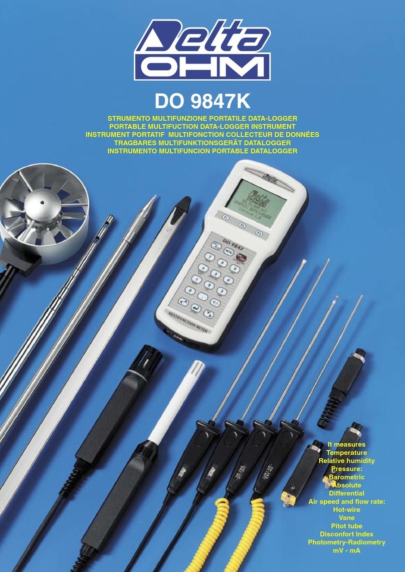
Delta OHM DO 9847K User manual

Delta OHM
Delta OHM HD32.1 User manual

Delta OHM
Delta OHM HD33M-MB.2 User manual

Delta OHM
Delta OHM HD50CR-AS User manual
