Savant USAI Operating instructions

USAI RECESS PINHOLE
SERVICE INSTRUCTIONS
CAUTION READ BEFORE INSTALLATION
• Retain these instructions for future reference. This product must be installed by a person familiar with the
construction and operation of the product and the hazards involved, in accordance with applicable NEC code.
• Switch off main power before beginning installation.
• Install per national installation and accident prevention regulations.
• Clearance between sides of luminaire and parts of building to be 1/2 inch minimum; clearance to insulating
materials to be 3 inch minimum, unless luminaire is IC rated.
• Fixtures must be installed in applications where the ambient temperature does not exceed 40oC during
normal operation.
• DO NOT connect or disconnect LED board wire connector when the fixture is energized. This may result in
permanent damage to the LED array.
• Warranty claims will not be accepted if incorrect driver or light engine is used.
Page 1
DRIVER REPLACEMENT:
Caution: Power Must Be Off!!
1. Remove trim.
2. Unplug Quick-Connector.
3. Remove driver plate by pulling towards opening
Driver Plate
4. Rotate driver plate.
5. Remove driver plate thru opening.
6. Unplug Quick-Connectors
7. Replace driver plate.
8. Install in reverse order. Remove thru
opening
Driver Plate
© 2018. USAI, LLC.
All rights reserved.
All designs protected by copyright.
Covered by US Patents. Patents pending.
I2-482
USAI®
Lighting
www.savant.com
1-877-SAVANT5
(1-877-728-2685)
3
4
5

USAI RECESS PINHOLE
SERVICE INSTRUCTIONS
CAUTION READ BEFORE INSTALLATION
• Retain these instructions for future reference. This product must be installed by a person familiar with the
construction and operation of the product and the hazards involved, in accordance with applicable NEC code.
• Switch off main power before beginning installation.
• Install per national installation and accident prevention regulations.
• Clearance between sides of luminaire and parts of building to be 1/2 inch minimum; clearance to insulating
materials to be 3 inch minimum, unless luminaire is IC rated.
• Fixtures must be installed in applications where the ambient temperature does not exceed 40oC during
normal operation.
• DO NOT connect or disconnect LED board wire connector when the fixture is energized. This may result in
permanent damage to the LED array.
• Warranty claims will not be accepted if incorrect driver or light engine is used.
Page 2
REFLECTOR REPLACEMENT FOR DOWNLIGHT:
Caution: Power Must Be Off
1. Remove trim from housing.
2. Remove thumb screws (2X).
3. Remove heatsink assembly.
4. Remove reflector by pulling.
5. Install reflector by aligning pins to reflector receptacle
and pushing into place.
6. Install heatsink assembly and secure with thumb screws (2X).
7. Make sure reflector is flush with glass.
8. Install trim into housing.
Thumb
Screw Thumb
Screw
Heatsink
Assembly
Reflector
LIGHT ENGINE REPLACEMENT FOR DOWNLIGHT:
Caution: Power Must Be Off
1. Loosen thumb screw (2X)
2. Lift and rotate heatsink assembly.
3. Remove reflector.
4. Remove cover mounting screws.
5. Remove cover.
6. Disconnect Light Engine.
7. Remove Light Engine mounting screws (3x).
8. Remove Light Engine holder.
9. Replace Light Engine.
10. Install remaining parts in reverse order.
Cover
Mounting
Screws
Light
Engine
Heatsink
Assembly
Reflector
Light
Engine
Holder
Light Engine
Mounting
Screws (3X)
Thumb
Screw
Cover
© 2018. USAI, LLC.
All rights reserved.
All designs protected by copyright.
Covered by US Patents. Patents pending.
I2-482
USAI®
Lighting
www.savant.com
1-877-SAVANT5
(1-877-728-2685)
2
3
4
1
2
9
7
8
5
3
4

USAI RECESS PINHOLE
SERVICE INSTRUCTIONS
CAUTION READ BEFORE INSTALLATION
• Retain these instructions for future reference. This product must be installed by a person familiar with the
construction and operation of the product and the hazards involved, in accordance with applicable NEC code.
• Switch off main power before beginning installation.
• Install per national installation and accident prevention regulations.
• Clearance between sides of luminaire and parts of building to be 1/2 inch minimum; clearance to insulating
materials to be 3 inch minimum, unless luminaire is IC rated.
• Fixtures must be installed in applications where the ambient temperature does not exceed 40oC during
normal operation.
• DO NOT connect or disconnect LED board wire connector when the fixture is energized. This may result in
permanent damage to the LED array.
• Warranty claims will not be accepted if incorrect driver or light engine is used.
Page 3
OPTIC REPLACEMENT FOR ADJUSTABLE:
Caution: Power Must Be Off
1. Remove trim from housing.
2. Loosen thumb screws (2X).
3. Remove optic by pulling.
4. Install optic by aligning pins to optic holder receptacle
and pushing into place.
5. Install heatsink assembly and secure with thumb screws (2X).
6. Make sure optic is flush with glass.
7. Install trim into housing.
Thumb
Screw
Optic
LIGHT ENGINE REPLACEMENT FOR ADJUSTABLE:
Caution: Power Must Be Off
1. Loosen thumb screw (2X)
2. Lift and rotate heatsink assembly.
3. Remove optic.
4. Disconnect Light Engine.
5. Remove Light Engine mounting screws (3x).
6. Remove Light Engine Holder.
7. Replace Light Engine.
8. Install remaining parts in reverse order.
Heatsink
Assembly
Thumb
Screw
Light Engine
Holder
Light
Engine
Optic Light Engine
Mounting
Screws (3X)
© 2018. USAI, LLC.
All rights reserved.
All designs protected by copyright.
Covered by US Patents. Patents pending.
I2-482
USAI®
Lighting
www.savant.com
1-877-SAVANT5
(1-877-728-2685)
2
3
2
1
7
6
65

USAI RECESS PINHOLE
SERVICE INSTRUCTIONS
CAUTION READ BEFORE INSTALLATION
• Retain these instructions for future reference. This product must be installed by a person familiar with the
construction and operation of the product and the hazards involved, in accordance with applicable NEC code.
• Switch off main power before beginning installation.
• Install per national installation and accident prevention regulations.
• Clearance between sides of luminaire and parts of building to be 1/2 inch minimum; clearance to insulating
materials to be 3 inch minimum, unless luminaire is IC rated.
• Fixtures must be installed in applications where the ambient temperature does not exceed 40oC during
normal operation.
• DO NOT connect or disconnect LED board wire connector when the fixture is energized. This may result in
permanent damage to the LED array.
• Warranty claims will not be accepted if incorrect driver or light engine is used.
Page 4
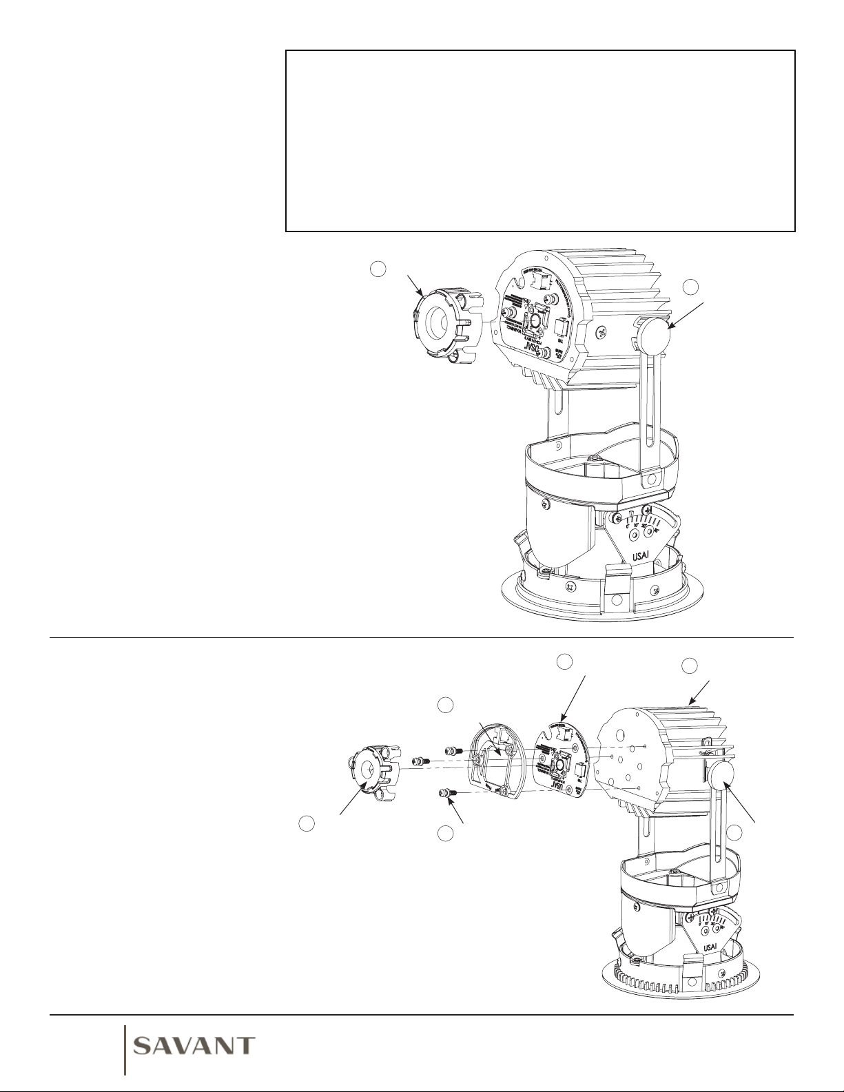
REFLECTOR REPLACEMENT FOR WALL WASH:
Caution: Power Must Be Off
1. Remove trim from housing.
2. Loosen thumb screws (2X).
3. Remove reflector by pulling.
4. Install reflector by aligning to reflector holder and pushing into place.
5. Install heatsink assembly and secure with thumb screws (2X).
6. Make sure reflector is flush with lens.
7. Install trim into housing.
Thumb
Screw
Heatsink
Assembly
Reflector
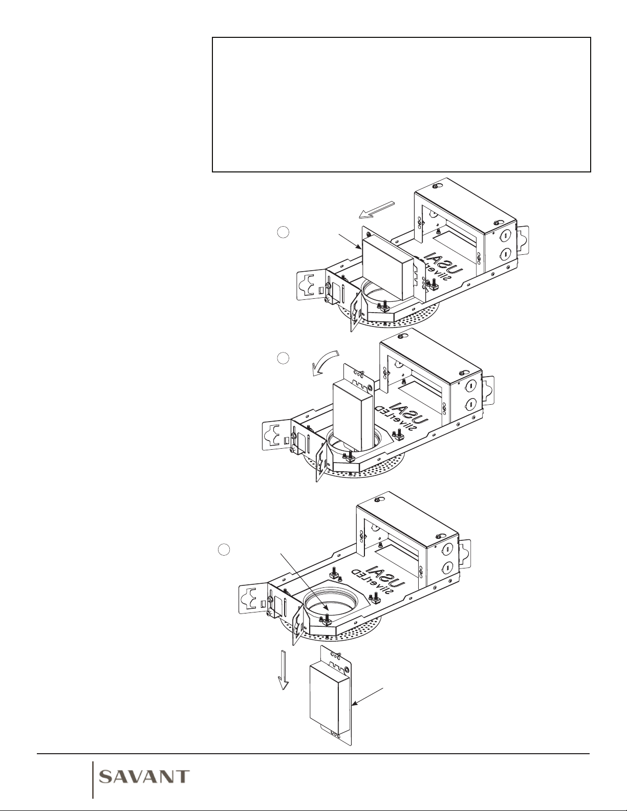
LIGHT ENGINE REPLACEMENT FOR WALL WASH:
Caution: Power Must Be Off
1. Loosen thumb screw (2X)
2. Lift and rotate heatsink assembly.
3. Remove reflector.
4. Remove cover mounting screws.
5. Remove cover.
6. Disconnect Light Engine.
7. Remove Reflector-holder mounting screws (3x).
8. Remove reflector-holder.
9. Replace Light Engine.
10. Install remaining parts in reverse order.
Reflector Holder
Heatsink
Assembly
Light Engine
Reflector Holder
Mounting Screws
(3X)
Cover
Reflector
Cover Mounting
Screws (3X)
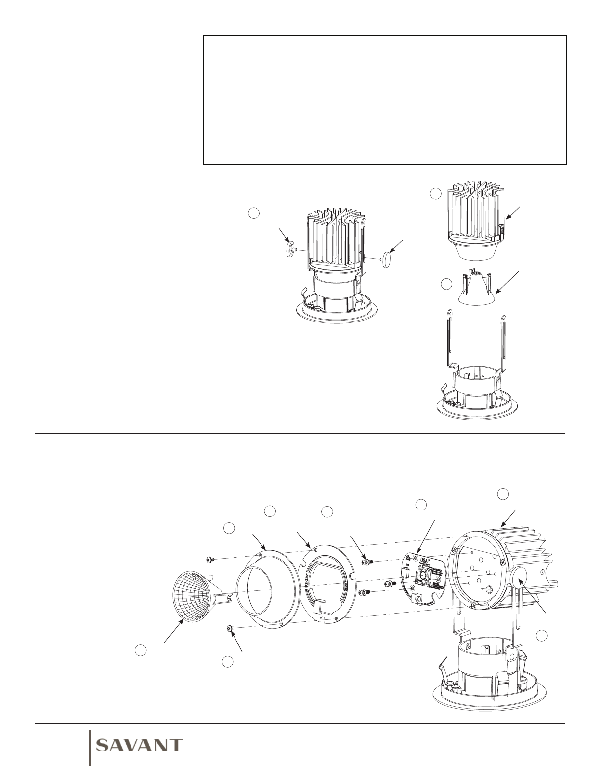
LENS REPLACEMENT FOR WALL WASH:
Caution: Power Must Be Off
1. Remove trim from housing.
2. Remove thumb screws (2X).
3. Remove heatsink assembly.
4. Remove mounting screw.
5. Remove mounting clip.
6. Replace lens.
7. Install mounting clip and secure with mounting screw.
8. Install heatsink assembly and secure with thumb screws (2X).
9. Make sure reflector is flush with glass.
10. Install trim into housing.
Thumb
Screw
Thumb
Screw
Heatsink
Assembly
Mounting Screw
Mounting Clip
Lens
Microfusion
Side Down
© 2018. USAI, LLC.
All rights reserved.
All designs protected by copyright.
Covered by US Patents. Patents pending.
I2-482
USAI®
Lighting
www.savant.com
1-877-SAVANT5
(1-877-728-2685)
3
2
4
5
6
3
2
2
Thumb
Screw
1
8
5
3
479
Other Savant Lighting Equipment manuals
Popular Lighting Equipment manuals by other brands

GigaTera
GigaTera RED Series installation guide

Heitronic
Heitronic 38037 Installation and operating instructions

EuroLite
EuroLite LED KLS-406 user manual

Energetiq
Energetiq LDLS EQ-9 Operation manual

LED World
LED World FA60M50-5M-24V-RGBCCT Important instructions

Pro-4 Tactical
Pro-4 Tactical Lantern with Red Flashers instruction manual