Savch S3800 Series User manual

S3800 Series Inverter
High performance Close-loop Vector Control (IM)
User manual
User Manual

S3800 Series Inverter
High performance close-loop vector control (asynchronous)
User Manual
File No. 520038131812
Vision No. V1.2
Filing time 2017-11-23
SAVCH electric provide a full range of technical support for our customers.
All users could contact with the nearest SAVCH office or service center,
also could contact with our headquarters directly.
SAVCH Electric reserves the copyrights and all rights,
Subject to change without further notice.

CONTENTS
PREFACE ......................................................................................................................................1
1 Safety Instructions .......................................................................................................................2
2 Hardware Description and Installation .........................................................................................5
2.1 Operational Environment .......................................................................................................5
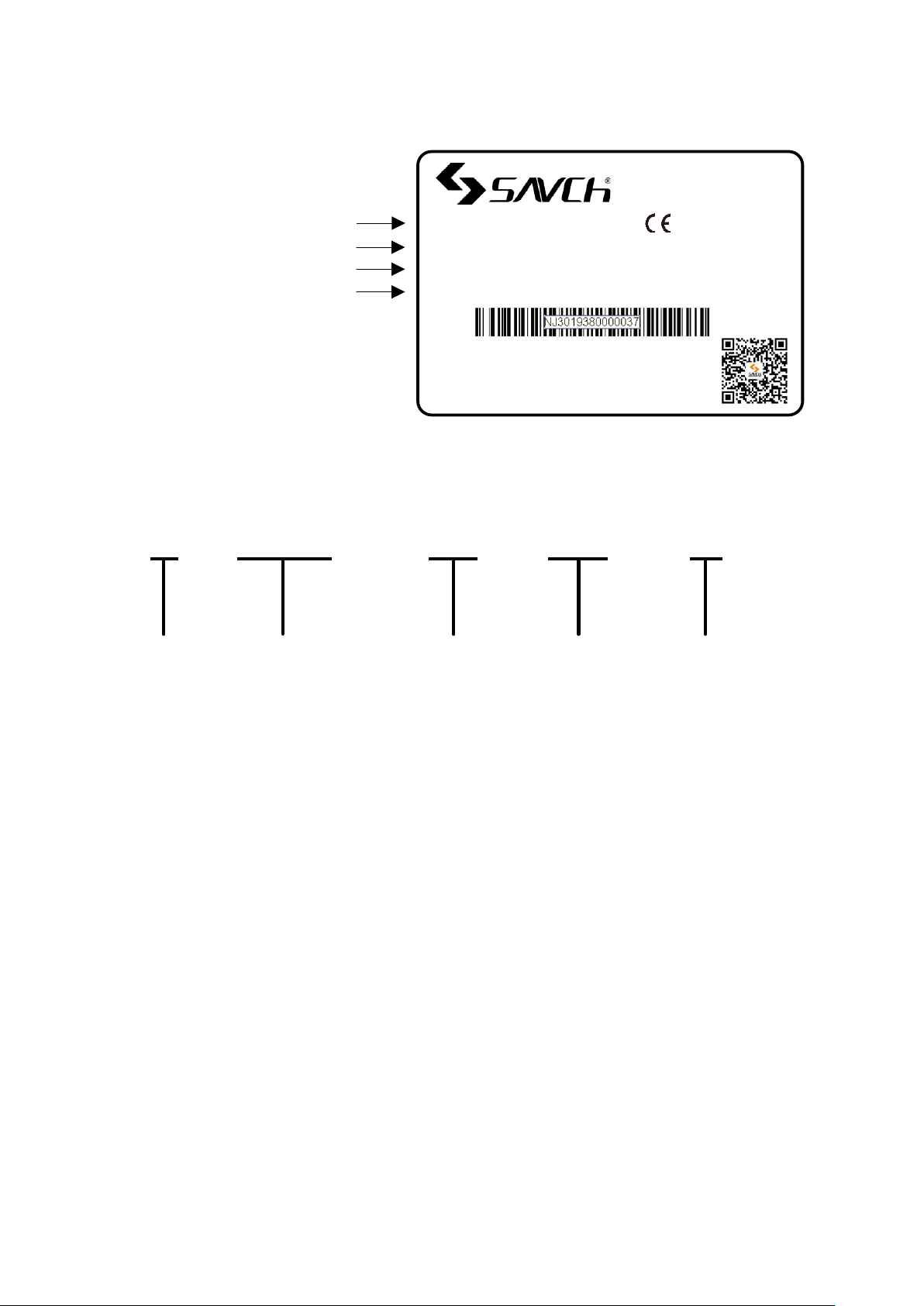
2.2 Model Description..................................................................................................................6
2.3 Inverter Specifications ...........................................................................................................7
2.4 Inverter Using and the Main Circurt wiring, the basic wiring diagram ...................................11
2.5 Operation Size.....................................................................................................................29
2.6 Inverter Size ........................................................................................................................30
3 Keypad Description ...................................................................................................................32
3.1 Overview of Keypad Functions ............................................................................................32
3.2 Overview of Operation Modes .............................................................................................34
3.3 Running Mode .....................................................................................................................34
3.4 Programming Mode .............................................................................................................36
3.5 Alarm Mode .........................................................................................................................47
4 Running.....................................................................................................................................48
4.1 Test Run ..............................................................................................................................48
4.2 Special Operations ..............................................................................................................59
5 Function Parameters List...........................................................................................................60
6 Function Parameters Description.............................................................................................105
00 Basic Functional Parameters ..............................................................................................105
01 External Terminal Function Parameters ..............................................................................148
02 Control Function Parameters..............................................................................................173
03 Motor 1 Parameters............................................................................................................182
04 High Performance Functions Parameters ...........................................................................186
05 Motor 2 Parameters, 06 Motor 3 Parameters, 07 Motor 4 Parameters................................208
08 Application Function 1 Parameters .....................................................................................212
09 Application Function 2 Parameters .....................................................................................230
10 Application Function 3 Parameters .....................................................................................241
11 Serial Communication Parameters.....................................................................................250
7 Failure Indication and Countermeasures .................................................................................260
7.1 Problems and Troubleshooting procedure .........................................................................262
7.2 Common Abnormal Motor Operation .................................................................................273
7.3 Other abnormal conditions.................................................................................................280

8 Maintenance And Inspection....................................................................................................282
8.1 Daily Inspection .................................................................................................................282
8.2 Periodic Inspection ............................................................................................................282
8.3 Measurement of Electrical Amounts in Main Circuit ...........................................................284
8.4 Insulation Test ...................................................................................................................285
9 Options....................................................................................................................................286
9.1 Braking Resistor List..........................................................................................................286
9.2 Input/Output AC/DC Reactor Specifications List for S3800 Series Inverter ........................287
9.3 Optional Card ....................................................................................................................287

1
PREFACE
Thank you for choosing SAVCH inverter! This instruction manual, which includes operation descriptions and
notes for maintenance, shall be delivered to the end-user.
For safety running and effective operation, this instruction manual shall be read thoroughly prior to use,
which shall also be preserved for later use. Provided problems occur and solution is not provided in this
instruction manual, contact your SAVCH ELECTRIC representative or contact with our company directly. Our
professional technicians will serve for you actively. And please continue to adopt products of SAVCH, give
valuable opinion and advice.
1. Reading Instructions
Symbols of” DANGER” and” CAUTION” in the manual indicates that, for safety running or maintenance of
inverters or other electrical products, attention shall be attached during delivering, installation, operation and
checks for the inverter. And these notes shall be applied for a better and safer operation.
DANGER If not used correctly, personnel damage even death may be caused.
△
!CAUTION If not used correctly, serious damage to inverter or machine may be resulted.
DANGER
●Never connect wires while power on. Do not check components or signal for circuit board during operation.
●Do not dismantle or change inner wire, circuit or components unnecessarily.
●Make sure grounding terminals are correctly grounded. 220V level:Grounding Ⅲ; 440V level:Special
Grounding
△
! CAUTION
●Do not perform a withstand voltage test for components of inverter, it can cause semi-conductor components
to be damaged by high voltage.
●Never connect the output terminals U,V,W to AC power supply.
●IC of CMOS on control circuit of the inverter shall be damaged by electrostatic influence. Do not touch main
circuit board.
2. Products Receiving
All products have been performed with strict test and inspection. After receiving the inverters, the following
checks shall be performed.
●To check that SAVCH inverter, an instruction manual is inside of the package.
●To check whether model number correspond with model and capacity your purchase order.
●To check whether there are damaged parts during transportation and delivering. If there are, do not connect
with power supply.
If any of the above checkpoints are not satisfactory, contact your SAVCH ELECTRIC representative for a quick
resolution.

2
1 Safety Instructions
1.1 Notes for Operation
Before wiring
△
! CAUTION
Specification of applying power supply shall correspond to input voltage of the inverter.
DANGER
Main circuit terminals must be correct, R/L1, S/L2 and T/L3 is input terminals and it’s forbidden to use mixing
with U/T1, V/T2 and W/T3. Failure to observe this may cause the inverter damaged.
Installation
DANGER
When handling the inverter, do not draw front cover directly but handle it by the heat sink to prevent the
cover from falling off and to avoid the falling of the inverter and causing personal injury or damage to the
inverter.
Install the inverter on a base made of metal or other non-flammable material, Do not place flammable object
nearby to prevent fires.
If several inverters are installed in a electric cabinet, add extra cooling fan to keep the temperature lower
than 40 ℃ to prevent over-heating or fire.
Operator shall be dismantled or refitted after power supply is off. Fixed operator shall be processed as
diagram shows.
Confirm whether the input voltage is identical with the voltage in the nameplate on the right side of the
inverter, Otherwise the malfunction could happen.
Operation
DANGER
Never put in or take off the motor during operation, otherwise over-current even over burning the main
circuit of the inverter may happen.
Do not remove the cover while current is flowing. Failure to observe this may result in electrical shock to
personnel.
When auto-restart function is set, do not approach the machine since motor can be reset suddenly after
being stopped.
Since STOP button can be selected by function set, which is different from usage of emergency stop/on
switch, attention shall be given to the usage.

3
△
! CAUTION
Never touch heat sink or discharging resistor since temperature may be very high.
Pay attention to relative settings before using the brake.
Do not check signals during running.
Turn off the power and check that the charging resistance lamp "CHARGE" goes out before reassembling or
checking.
Check and maintenance
△
! CAUTION
Ambient temperature for operating the inverter shall be -10℃ to + 40℃ and 90%RH non condensation.
After removing the dust-cover, ambient temperature for operating the inverter shall be -10℃ to + 50℃ and
95%RH non condensation. However under this condition, the ambient environment must be without drips of
water or metal dust. If there are, the dust cover shall be refitted and check whether ambient temperature is
with in -10℃ to + 40℃ simultaneously.
Disposal precaution
△
! CAUTION
Explosion may occur when burning the electrolytic capacitor of the main circuit and printing plate. Toxic gas
may be generated when burning control panel and other plastic fittings.
It shall be treated as Industrial waste when disposing of it.

4
1.2 Notes for Operation Environment
Direct sunlight Corrosive gas or fluids Oil
Radioactive materials Locations of inflammable
materials
Extreme low temperatures Extreme high ambient
temperatures (Above 40℃)
Large impelling
Salt or saline Rain, moisture Iron chips and dust
?
Electromagnetic waves
and ultra high-angle rays
(For example:locations of
welding machines and etc.)
Oil
cool
Below 10 degrees Celsius
Force
Force
Force
Force
Force
Force
Salt

5
2 Hardware Description and Installation
2.1 Operational Environment
Since operation environment can directly influence functions and operation life, to ensure proper
performance and long operation, follow the recommendations below when choosing allocation for installing
the inverter:
●Use only with the ambient temperature range:-10℃ to + 40℃; -10℃ to + 50℃ applicable when dust
cover is removed.
●Rain, moisture
●Direct sunlight.(Avoid using outdoors)
●Corrosion of oil sprays or salt
●Corrosive fluid and methane
●Dust or batting and metallic particles in the air
●Radioactive materials and inflammable materials
●Electromagnetic interference (Avoid using together with welding machine or dynamic machines.)
●Vibration. (If inverter must be used in this environment, an anti vibration pad is necessary).
Attention shall be attached to clearance of inverters allocated closely. A fan shall be installed to make sure
temperature is lower than 40℃
INSIDE THE
CABINET
(FALSE)
AIR EXCHANGE FAN
INSIDE THE
CABINET
INSIDE THE
CABINET
(CORRECT)(FALSE)(CORRECT)
INSIDE THE
CABINET
AIR EXCHANGE FAN
For cooling off, face shall be toward front and upper parts shall be upwards.
Clearance shall meet the following specifications:(If the inverter is installed inside the cabinet or
environment is allowable, dust cover shall be available to be removed for ventilating.)
(a)FRONT
SAVCH
DIRECTION
OF
INSTALLATION
12cm 12cm
12cm
12cm
5cm
(b)SIDE
VENTILATION
-10-+40℃

6
2.2 Model Description
Model
Input power supply Spec
Output power supply Spec
Output frequency
TYPE: S3800-4T1.5G
SOURCE: AC 3PH 380~480V 50/60Hz
OUTPUT: 3PH 0~480V 2.8kVA 4A
FREQUENCY RANGE: 0.1~500Hz
S/N:
NJ3019380000037
SAVCH ELECTRIC CO.,LTD
Designed by Savch Electric
Product series
name
S 3800 - 4T 1.5 G
Input power
source:
4T: 3 ph 440V
Applicable
motor rating
1.5:1.5kW
2.2:2.2kW
. .
. .
. .
22:22kW
. .
. .
. .
110:110kW
SAVCH G: General

7
2.3 Inverter Specifications
2.3.1 Standard specifications
(1.5 to 110kW) HD (Heavy Duty) spec for heavy duty
Item
Specifications
Type(S3800-4T***G)
1.5
2.2
4.0
5.5
7.5
11
15
18.5
22
Nominal applied motor[kW]( *1)(rated
output)
1.5
2.2
3.7
5.5
7.5
11
15
18.5
22
Rated
output
Rated power [kVA] (*2)
2.8
4.1
6.8
10
14
18
24
29
34
Voltage [V]
3 ph 380~480V(With AVR function)
Rated current [A]
4
5.5
9
13.5
18.5
24.5
32
39
45
Overload capability
150%-1min,200%-3.0s
Input
power
Voltage, frequency
380~480V,50Hz /60Hz
Voltage, frequency variations
Voltage:+10~15%(Interphase unbalance rate is within 2%,
frequency:+5~-5%)
Required power supply
capacity(with DCR) [kVA] (*3)
2.1
3.2
5.2
7.4
10
15
20
25
30
Rated input current (without
DCR) [A]
5.9
8.2
13
17.3
23.2
33
43.8
52.3
60.6
Rated input current (with
DCR) [A]
—
Braking
Braking torque [%](*4)
100%
20%
Braking transistor
Standard built-in
Built-in braking resistance
5s
Braking time [s]
Duty cycle [%ED]
5
3
2
DC reactor(DCR)
Optional (*5)
Enclosure
IP20 closed type
Cooling method
Natural
cooling
Fan cooling
Item
Specifications
Type (S3800-4T***G)
30
37
45
55
75
90
110
Nominal applied motor[kW]( *1)(rated
output)
30
37
45
55
75
90
110
Rated
output
Rated power [kVA] (*2)
45
57
69
85
114
134
160
Voltage [V]
3 ph 380~480V(With AVR function)
Rated current [A]
60
75
91
112
150
176
210
Overload capability
150%-1min,200%-3.0s
Input
power
Voltage, frequency
380~480V,50Hz /60Hz
Voltage, frequency variations
Voltage:+10~15%(Interphase unbalance rate is within 2%,
frequency:+5~-5%)
Required power supply
capacity(with DCR) [kVA] (*3)
40
48
58
71
96
114
140
Rated input current (without
DCR) [A]
—
Rated input current (with
DCR) [A]
62
76
91
105
140
160
210
Braking
Braking torque [%](*4)
10~15%
Braking transistor
—
Built-in braking resistance
—
Braking time [s]
Duty cycle [%ED]
—
DC reactor (DCR)
Standard built-in
Optional (*5)
Enclosure
IP00
Cooling method
Fan cooling

8
(5.5 to 110kW) ND (Normal Duty) spec for light duty
Item
Specifications
Type(S3800-4T***G)
5.5
7.5
11
15
18.5
22
30
37
45
55
75
90
110
Nominal applied
motor[kW]( *1)(rated output)
7.5
11
15
18.5
22
30
37
45
55
75
90
110
132
Rated
output
Rated power [kVA] (*2)
12
17
22
28
33
45
57
69
85
114
134
160
192
Voltage [V]
3 ph 380~480V(With AVR function)
Rated current [A]
16.5
23
30.5
37
45
60
Overload capability
120%-1min
Input
power
Voltage, frequency
380~480V,50Hz /60Hz
Voltage, frequency
variations
Voltage:+10~15%(Interphase unbalance rate is within 2%, frequency:+5~-
5%)
Required power supply
capacity(with DCR)
[kVA] (*3)
10
15
20
25
30
40
48
58
71
96
114
140
165
Rated input current
(without DCR) [A]
23.2
33
43.8
52.3
60.6
77.9
—
Rated input current
(with DCR) [A]
—
76
91
105
140
160
210
240
Braking
Braking torque [%] (*4)
70%
15%
7~12%
Braking transistor
Standard built-in
—
Built-in braking
resistance
—
Braking time [s]
Duty cycle [%ED]
—
DC reactor(DCR)
Optional (*5)
Standard built-in
Optional (*5)
Enclosure
IP20 closed type
IP00
Cooling method
Fan cooling
(*1) Suitable 4-pole standard motor.
(*2) Rated capacity is calculated by assuming the output rated voltage as 440V.
(*3) Obtained when a DC reactor (DCR) is used.
(*4) Average braking torque for the motor running alone.(It varies with the efficiency of the motor)
(*5)DC reactor (DCR) is optional part, inverter of 75KW or above must use together with the DC reactor (DCR).
2.4.2 Common specifications
Item
Explanation
Output frequency
Setting
range
Max. frequency
25 to 500 Hz (120 Hz for inverters in ND mode)
(120 Hz under vector control without speed sensor, 200 Hz under vector
control with speed sensor).
Base frequency
25 to 500 Hz (in conjunction with the maximum frequency)
Starting frequency
0.1 to 60.0 Hz (0.0 Hz under vector control with/without speed sensor)
Carrier frequency
·0.75 to 16 kHz (HD mode:1.5 to 45 kW, ND mode:5.5 to 18.5 kW).
·0.75~10kHz(HD mode:55~200kW,ND mode:22~45kW)
·0.75~6kHz(ND mode:55~200kW)
Note:The carrier frequency may automatically drop depending upon the
surrounding temperature or output current to protect the inverter. (The
automatic drop function can be disabled)
Frequency output
accuracy(Stability)
·Analog setting:±0.2% of maximum frequency (at 25 ±10℃)
·Keypad setting:±0.01% of maximum frequency (at -10 to +50℃)
Setting resolution
·Analog setting:1/3000 of maximum frequency (1/1500 for AUI input)
·Keypad setting:0.01 Hz (99.99 Hz or less), 0.1 Hz (100.0 to 500.0 Hz)
·Link operation setting:1/20000 of maximum frequency or 0.01 Hz (fixed)

9
Item
Explanation
Under V/F control
of with speed
sensor Under
Dynamic torque
vector control with
speed sensor
Speed
control
range
·1 :100 (Minimum speed:Base speed, 4P, 7.5 to 1500 r/min)
·1 :2 (Constant torque range:Constant output range)
Speed
control
accuracy
·Analog setting:±0.2% of maximum speed (at 25 ±10℃)
·Digital setting:±0.01% of maximum speed (at -10 to +50℃)
Under Vector
control without
speed sensor
Speed
control
range
··1 :200 (Minimum speed:Base speed, 4P, 7.5 to 1500 r/min)
·1 :2 (Constant torque range:Constant output range)
Speed
control
accuracy
·Analog setting:±0.5% of maximum speed (at 25 ±10℃)
·Digital setting:±0.5% of maximum speed (at -10 to +50℃)
Under Vector
control with speed
sensor
Speed
control
range
·1 :1500 (Minimum speed:Base speed, 4P, 7.5 to 1500 r/min)
·1 :4 (Constant torque range:Constant output range)
Speed
control
accuracy
·Analog setting:±0.5% of maximum speed (at 25 ±10℃)
·Digital setting:±0.01% of maximum speed (at -10 to +50℃)
Control
Control method
·V/f control
·Dynamic torque vector control
·V/F control of with speed sensor,Dynamic torque vector control with speed
sensor
·Vector control without speed sensor
·Vector control with speed sensor (with an optional PG interface card
mounted)
Voltage/frequency
characteristics
·Possible to set output voltage at base frequency and at maximum
frequency
·AVR control ON/OFF selectable. Non-linear V/F pattern with three arbitrary
points
Torque boost
·Auto torque boost (for constant torque load)
·Manual torque boost:Desired torque boost (0.0 to 20.0%) can be set
·Select application load with function (Constant torque load or variable
torque load)
Starting torque
·22 kW or below:200% or over, 30 kW or above:180% or over
Reference frequency:0.3 Hz with slip compensation and auto torque boost
Start/stop operation
·Keypad (RUN/STOP keys), external signals (run forward (run reverse)
run/stop command etc.), Communications link (RS485).
Frequency Setting
·Keypad ( Can use UP/DOWN keys to set)
·Analog input:DC0 to ±10V/0 to ±100%( terminal AVI,AUI):DC 4 to 20mA/0
to 100% (terminal AVI)
·UP/DOWN operation:Multi-frequency (16 steps), 16-bit parallel
·Pulse train input (standard):Pulse input = MI7 terminal, Rotational direction
= general terminals
·Reference frequency switching, Remote/local mode switching, Auxiliary
frequency setting, Proportional operation setting, and Inverse operation.
Acceleration/ deceleration
time
·0.00 to 6000 s,Linear/S-curve/curvilinear, Acceleration/deceleration time
settings 1 to 4 switchable.
Stop control
·Running continued at the stop frequency, coast-to-stop, or force to stop
·DC braking:Braking starting frequency (up to 60 Hz), time (up to 30.0 s),
and operation level (up to 100%).
·Zero speed control (under vector control with speed sensor)
Auto-restart after momentary
power failure
·Trip immediately, trip after recovery from power failure, trip after
deceleration to stop.
·Continue to run, restart at the frequency at which the power failure
occurred, restart at the starting frequency, restart after searching for idling
motor speed.
Hardware current limiter
·Current limiter operation level (20 to 200%)
·Over current limiting by hardware (it can be canceled)
Torque limiter
·Torque limit value (±300%)
·Torque limiter 1/2, torque limiter enabled/disabled, analog torque limit
value.

10
Item
Explanation
Control
Control functions
·Analog input adjustment (gain/offset/filter time constant), frequency limiter (high and
low), bias frequency, jump frequency, jogging operation, pre-excitation, switch to
commercial power, commercial power switching sequence,cooling fan ON/OFF
control, select motor 2 to 4, protect motor from dew condensation, universal DI,
universal DO,universal AO, rotational direction limitation.
·Overload prevention control, auto search, slip compensation, over voltage stall
prevention,droop control, PID process control, PID dancer control, Deceleration
characteristics (improving braking capability),auto energy saving function.
·Auto-tuning (Operating modes:motor load, do not connect the mechanical
transmission parts.)
·Light alarm, retry, command loss detection.
Digital input
Run/stop forward and reverse command, select multi-frequency , select ACC/DEC
time, Enable 3-wire operation , Coast-to-stop command,reset alarm, enable external
alarm trip, ready for jogging, select frequency command 2/1, select motor 1 to 4,
enable DC braking, select torque limiter level, switch to commercial power ,
UP/DOWN command, enable data change with keypad, cancel PID control, switch
normal/inverse operation, interlock,cancel torque limiter, enable communications link
via RS485, universal DI, select starting characteristic, force to stop, pre-excitation,
reset PID integral and differential components, hold PID integral component,select
local (keypad) operation, protect the motor from dew condensation, enable internal
sequence to commercial lines , pulse train input, pulse train sign, cancel constant
peripheral speed control,hold constant peripheral speed control frequency in the
memory, switch to commercial power operation (motor 1 to 4), select droop control,
servo-lock command (under PG vector control),cancel PG alarm (under PG vector
control),cancel user logic,clear all user logic timers.
Transistor output
Inverter running, frequency arrival signal 1/3, frequency detected (3 points), under
voltage detected (inverter stopped), torque polarity detected, inverter output limiting,
auto-restarting after momentary power failure, motor overload early warning, keypad
operation, inverter ready to run, switch motor power between commercial line and
inverter output (inverter input/output/commercial power), select the AX terminal
function (primary side MC), inverter output limiting with delay, cooling fan in operation,
auto-resetting, universal DO, heat sink overheat early warning, service lifetime alarm,
reference loss detected, inverter operating, overload prevention control, current
detected (3 points), low level current detected, PID alarm, under PID control, PID
control stopped due to slow flowrate, low output torque detected, torque detected (2
points), switched to motor 1 to 4, run forward signal, run reverse signal, inverter in
remote operation, PTC status detection enabled, brake signal, analog frequency
reference loss on the terminal [ACI], inverter keeping speed output, speed arrived,
PG error detected, maintenance timer, light alarm, alarm relay contact output (for any
fault), braking resistor broken, positioning completion signal, user logic output signal.
Analog output
·Terminals AFM:Output a selected signal with DC voltage (0 to +10V) or DC current
(4 to 20 mA)
·Terminals DFM:Output a selected signal with pulse (25 to 6000p/s log voltage (0 to
+10V)
<Selectable output signals>
Output frequency (before slip compensation, after slip compensation), output current,
output voltage, output torque, load factor, input power, PID feedback amount, speed
(PG feedback value), DC link bus voltage, universal AO, motor output, calibration,
PID command, PID output.
Indication
Running /stopping
Speed monitor (reference frequency (Hz), output frequency, motor speed, load shaft
speed, line speed, speed in %). Output current, output voltage, torque calculation
value, input power, PID command value, PID feedback amount, PID output, load
factor, motor output, torque current, flux command, analog signal input monitor,
cumulative inverter run time, cumulative motor run time, input watt-hour, number of
startups, I/O checking, energy-saving monitor.
Alarm information
Alarm history:Saves and displays the last 4 alarm code and their detailed description
Others
Communications
RS485 COM port 1 (for keypad connection), RS485 COM port 2 (on terminal block)
Protection against
momentary power
failure
Upon detection of a momentary power failure lasting more than 15 ms, this function
stops the inverter output. If restart after momentary power failure is selected, this
function invokes a restart process if power is restored within a predetermined period
(allowable momentary power failure time).

11
2.4 Inverter Using and the Main Circurt wiring, the basic wiring diagram
2.4.1 Peripheral equipment application and precautions
No fuse
Breaker
Magnetic
Contactor
Inverter
Input side
Noise Filter
Power Improving
AC Electric
Reactor
Motor
Grounding
Zero Phase
Noise Filter
Power supply
Power:
●Use the power supply in the permissible specifications of the inverter model to
avoid damaging the drive.
No fuse circuit breaker(MCCB):
● A non-fuse circuit breaker (MCCB) must be installed between the AC power
supply and the inverter, but do not use it as inverter's operation / stop switching
function.
● Use a non-fuse circuit breaker (MCCB) that complies with the rated voltage
and current rating of the inverter. When the capacity is selected, it is at least 2
times the sum of the rated output current of the inverter (mainly considering
150% of the inverter overload,1min).
Leakage circuit breaker(RCD/ELCB):
● Please install the leakage circuit breaker, to prevent leakage caused by the
malfunction and to protect the safety of the use of personnel;
● Each inverter should use a dedicated circuit breaker whose sensitive current
is more than 30mA;
● When using an ordinary circuit breaker, the current sensitivity must be more
than 200mA, operation Time must be more than 0.1s.
Electromagnetic contactor:
● Normally, there is no need to add electromagnetic contactor, but it can be
used as an external control protection, automatic restart after power failure and
other functions,must install electromagnetic contactor.
● When using the brake unit, please connect to the thermal relay contact of the
brake unit, close the electromagnetic contactor when overheating;
● Do not use the electromagnetic contactor as the inverter's operation / stop
switching function, which will shorten the life of the inverter.
Power Improvement AC Reactor:
●If a large capacity (500KVA or more) is used for the inverter, an excessive
peak current may flow into the input side of the inverter, and the rectifier
element may be damaged. In this case, the AC reactor can also improve the
power factor on the power supply side.
Input side noise filter:
● It is possible to remove the noise from the power supply line into the inverter
and to reduce the noise from the inverter to the power supply line.
● When there is an inductive load around the inverter, please ensure to install it.
Inverter:
●Input power terminals R / L1, S / L2, T / L3 are connected without any phase
sequence.
●The output terminals U / T1, V / T2, W / T3 are connected to the U / T1, V / T2,
W / T3 terminals of the motor. If the inverter is running forward, the motor is
reversed. / T2, W / T3 terminal in any two can be adjusted.
●Do not connect output terminals U, V, W to AC power to avoid damage to the
inverter.
●Ground terminal should be properly grounded, 220V level: grounding
resistance should be below 100Ω, 440V class: grounding resistance should
be10Ω or less.
Zero phase filter:
● When you want to reduce the electromagnetic interference caused by
the inverter, it is effective in the range of 1MHz ~ 10MHz. The more the
number of the motor wires are bypassed, the better.
Install as close to the inverter as possible,suitable for either the input side or
output side of the inverter.

12
Wiring shall be checked whether correct or not. Peripheral wiring shall fulfill the following
requirements.
(Warning:Do not use a buzzer of control circuit to check wiring)
(A)Wiring for control circuit Power supply must be isolated or far from other high voltage wirings or high
current power lines, thus electromagnetic interference can be avoided. See diagrams below:
●Individual power supply bridge for inverter
MCCB
Power
supply
IM
S3800
●If inverter power supply circuit is used commonly
with other machines, inverter-specialized noise
filter or isolating transformer shall be added.
S3800
MCCB
Machine
MCCB
Power
supply Speci
alized
noise
filter
IM
MCCB
IM
S3800
Machine
Isolated transformer
Power
suppy
●Good effect may not be received if general use
noise filters are applied
MCCB
Power
supply
IM
S3800
Machine
Genera
noise
filter
MCCB
MCCB
Power
supply
IM
S3800
Machine
Genera
noise
filter
MCCB
●Interference during transmission can be prohibited by adding an inverter-specialized noise filter at main
circuit output side. For preventing electromagnetic radiation, a metal tube shall be installed, and distance
from signal wiring of other control machines shall be 30cm at least
Signal wire
IM
30cm above
Power
supply
MCCB Iron box
S3800
Noise
filter
Noise
filter
Control
machine

13
●Voltage drop of wiring shall be considered providing that inverter and motor are with an excessive
distance.Voltage drop (V) =
3
× wiring resistance (Ω/km) × wire length (m) × current × 10-3, load wave
frequency shall be modified according to wiring prepared.
Distance between inverter and motor wiring
Below 50M
Below 100M
Above 100M
Allowable load wave no.
Below 12kHz
Below 9kHz
Below 6kHz
Set value for parameter 00.26
12
9
6
(B)Wiring for control circuit shall be isolated or far from main circuit wiring or other high voltage/current
power lines, thus electromagnetic interference shall be avoided.
●For preventing electromagnetic interference and false sequence, shielding wiring shall be used for control
circuit. Shielding wiring shall connect grounding terminals.
Distance for wiring shall be 50m or less.
Armor
Shielding Layer
Never connect
Insulate these parts with
insulation tape
To ground terminal
(See filter Wiring Specification)
(C) Grounding terminal for inverters shall be grounded properly. 220V:Ground resistance below 100Ω,
440V:ground resistance below 10Ω.
●AWG shall be taken as electrical equipment technical standard for ground wire. Ground wire shall be as
short as possible.
●Never ground simultaneously for Inverter ground wire with other large current load (such as welding
machine or large Power motors). They shall be grounded separately.
●Ground circuit shall be avoided when several inverters are grounded simultaneously.
(a) CORRECT (b) CORRECT (c) FALSE
(D)Cable line width for main circuit and control circuit shall be selected according to power line
standard.
(E) After completing of grounding and wiring, check for the following items:wiring is proper; wire is not
broken and screws are securely tightened.

14
2.4.2 The selection of peripheral devices
Moulded Case Circuit Breaker (MCCB) / Earth Leakage Circuit Breaker (ELCB)
Supply
voltage
Applicable standard
motor(kW)
Type of inverter
Specification
Rated Current (A) of MCCB, ELCB
DC reactor
Yes
No
3-phase
440V
1.5
S3800-4T1.5G
HD
5
10
2.2
S3800-4T2.2G
10
15
3.7
S3800-4T4.0G
20
5.5
S3800-4T5.5G
HD
15
30
7.5
ND
20
40
S3800-4T7.5G
HD
11
ND
30
50
S3800-4T11G
HD
15
ND
40
60
S3800-4T15G
HD
18.5
ND
75
S3800-4T18.5G
HD
22
ND
50
100
S3800-4T22G
HD
30
ND
75
125
S3800-4T30G
HD
37
ND
100
S3800-4T37G
HD
45
ND
150
S3800-4T45G
HD
55
ND
125
200
S3800-4T55G
HD
75
ND
175
-
S3800-4T75G
HD
90
ND
200
S3800-4T90G
HD
110
ND
250
S3800-4T110G
HD
132
ND
300
Note: In order to avoid the residual current circuit-breaker error, please choice the induction current with 200mA
or above, and operation time with 0.1s or above.

15
Recommended Screw Speciation
Supply
voltage
Type of inverter
Screw Speciation
Reference
Main circuit
Grounding
Control power auxiliary
input [R1, T1]
Screw
Size
Torque
(N·m)
Screw
Size
Torque
(N·m)
Screw Size
Torque
(N·m)
3 phase
440V
S3800-4T1.5G
M4
1.8
M4
1.8
M3.5
1.2
Figure A
S3800-4T2.2G
S3800-4T4.0G
S3800-4T5.5G
M5
3.5
M5
3.5
Figure B
S3800-4T7.5G
S3800-4T11G
S3800-4T15G
M6
5.8
M6
5.8
Figure C
S3800-4T18.5G
S3800-4T22G
S3800-4T30G
M6
5.8
M6
5.8
M4
1.8
Figure D
S3800-4T30G
M8
13.5
M8
13.5
Figure E
S3800-4T37G
S3800-4T45G
S3800-4T55G
S3800-4T75G
M10
27
M10
27
Figure F
S3800-4T90G
S3800-4T110G
Figure A
The width of above-mentioned terminals is 9.75
Figure B

16
Figure C
Figure D
Figure E
Figure F
This manual suits for next models
13
Table of contents
Other Savch Inverter manuals