2
1. TECHNICAL SPECIFICATIONS
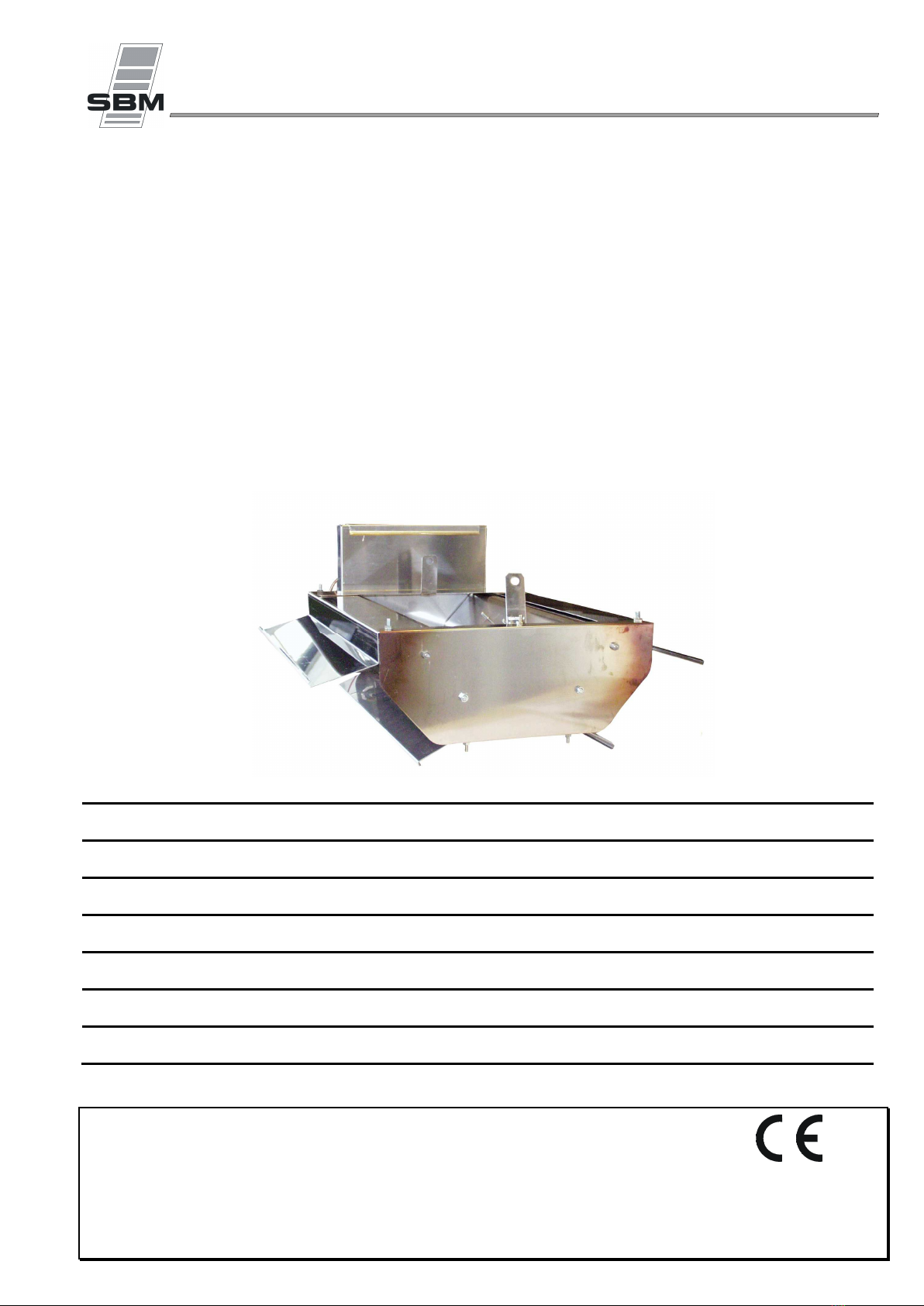
Refer to the rating plate on the filter box holder
(see example opposite)
230V (+10% -15%) / 50Hz - 60Hz / 2 x 0.1A
0 to 180 mbar (nominal 148 mbar)
certificate number 1312 AR 1201
Nominal capacity (inlet pressure = 148 mbar) ∑Qn (Hs)
(Nominal heat input) ∑Qn (Hi) 7.452
10.580
14.260
kW
Maximum capacity (inlet pressure = 180 mbar) ∑Qm (Hs) 8.932
12.682
17.093
kW
(Maximal heat input) ∑Qm (Hi) 8.218
11.668
15.726
kW
Gas consumption (inlet pressure = 148 mbar) M
(Mass flow rate) (inlet pressure = 180 mbar) M 0.649
0.912
1.237
kg/h
Ø orifices (1/100e mm) primary orifice (restrictor) none
none
secondary orifice (injector) 2 x 70
2 x 78
2 x 95
Combustion air 7.452
10.580
14.260
m
/h
Inlet pressure 60 to 180 mbar (nominal 148 mbar)
certificate number 1312 AR 1201
Nominal capacity (inlet pressure = 148 mbar) ∑Qn (Hs)
(Nominal heat input) ∑Qn (Hi) 7.293
10.355
13.957
kW
Maximum capacity (inlet pressure = 180 mbar) ∑Qm (Hs) 8.932
12.682
17.093
kW
(Maximal heat input) ∑Qm (Hi) 8.043
11.420
15.392
kW
Gas consumption (inlet pressure = 148 mbar) V
(Volumetric flow rate) (inlet pressure = 180 mbar) V 0.852
1.210
1.629
m
/h
Ø orifices (1/100e mm) primary orifice (restrictor) 1 x 135
1 x 180
secondary orifice (injector) 2 x 115
2 x 135
2 x 150
Combustion air 7.293
10.355
13.957
m
/h
Hi = Net calorific value - Hs = Gross calorific value
The proper operation of the heaters requires the renewal of 1 m3/h fresh air per kW of
operating capacity.
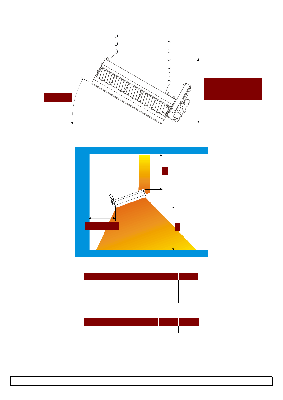
X (mm) 272 398 522
Weight (kg)
7.00 8.00 9.00