SC VL-Channel User manual

Operation, Maintenance and
Repair Manual for
Model VL-Channel
Products manufactured by Safety Clamps, Inc. meet
and/or exceed ANSI/ASME B30.20 standards
Warning
Prior to operating your Safety Clamp, please ensure
All operators read and understand this manual.
Effective January 1, 2016
This manual supersedes all previous VL-Channel manuals.
Safety clamps, inc.
Home of the “big Bite” Lifting Clamp

GENERAL INFORMATION
1. The Model VL-Channel is designed to lift and transfer angles and bulb
profiles for fabrication and erection of steel.
2. Always choose the proper clamp and rated capacity for the material to
be lifted.
3. The Model VL-Channel may be used to lift material from a vertical
position (Fig. 1) or from horizontal to vertical to horizontal through
a 180° arc (Fig. 2).
4. The Model VL-Channel is rated to lift material with a hardness up to
450 Brinell (48 Rockwell C).
5. Do not use the Model VL-Channel to lift plate steel.
6. The Model VL-Channel has a locking handle that locks the clamp open
to facilitate loading and unloading, and locks the clamp closed onto the
material for a more secure lift. Always store the clamp in the locked
open position.
7. The locking handle also has a remote release design and, when
needed, the operator can attach a tag line and safely lock the clamp
open from a distance once the load has been securely positioned and
the weight of the load is removed from the clamp.
8. The operator must read and understand the Operator’s Manual before
using a Safety Clamp.
Safety Clamps, Inc. Model VL-Channel
1
Serial # _______________________
Model _______________________
Max. Rated
Capacity in Tons _______________________
Jaw Opening _______________________
Safety Clamps, Inc.
Repair Service Center
Call 1-800-456-2809 for a Return AuthorizationΝumber.
Include:
Model
Rated Capacity
Serial Number
You will receive a written quote within 24 hours of receipt of your
Safety Clamp.
Your Safety Clamp will be repaired, tested, re-certified, painted, and
shipped within 24 hours of authorization.
We also perform periodic inspections and re-certifications.
It’s that easy! Call 1-800-456-2809 for more details.
Register Your Clamp
Go to www.safetyclamps.com to register your clamp to receive the most
appropriate service and product support for your clamp and new product
updates as they come available.
10 Year Limited Warranty
All products manufactured by Safety Clamps, Inc. carry a limited warranty
that the product is free from defects in materials and workmanship. This
warranty applies only to the original end user of the clamp and is valid for 10
years from the date of purchase.
Conditions
This warranty only covers defects in materials and workmanship and only if
the clamp has been inspected, maintained, and operated within the
guidelines of the clamp’s Operation, Maintenance, and Repair Manual. The
warranty does not cover wear to parts such as pins, grippers, lock springs,
etc. If a defect is found within the warranty period, the clamp will be repaired
or replaced by determination of the manufacturer.
No warranty is given due to: regular wear; incorrect use; overload;
modification of the clamp; improper maintenance and/or repair. Figure 1 Figure 2

OPERATING AIDS
1. The Model VL-Channel should not be used to handle material with
temperatures below 0° F or above 225° F. These temperature
restrictions apply to both the ambient temperature and the
temperature of the material to be lifted.
2. Do not use the VL-Channel clamps for horizontal transfer of materials.
3. Do not use clamps on materials with a hardness in excess of
450 Brinell (48 Rockwell C).
Warning: Do Not lift plate steel with the Model VL-Channel clamp.
4. Never exceed ten degrees (10°) side load with a VL-Channel clamp
that has a standard lifting shackle (Fig. 3).
5. Make sure the load to be lifted is properly balanced. Multiple clamps
may be needed to balance the load.
6. Never lift or transfer material over or near people.
7. Always lock the clamp closed before making a lift. Do not make a lift
with the lock in the open or locked open position.
8. Do not lift clamp with an open-end hook.
9. Do not alter clamp. Do not weld, grind, or modify the clamp in any way.
10. If a clamp has been overloaded or damaged in any way, take the
clamp out of service immediately.
11. Do not improvise and misuse the clamp. Always use correct clamp for
the lift.
Safety Clamps, Inc. Model VL-Channel
2
Figure 3: Never exceed 10° side loading with a VL-Channel clamp unless using a
clamp with a Universal Lifting Shackle (Fig. 6).
OPERATION
Inspection Before and After Each Use
The Safety Clamps inspection procedures meet and/or exceed the
requirements set forth in the ASME B30.20 Below-the-Hook Lifting Devices
guideline.
1. Before using any Safety Clamp, the operator must read and understand
the Operator’s Manual in its entirety.
2. All Safety Clamps should be inspected before and after each use.
Do not use if any components are bent, elongated, gouged, nicked
excessively, worn, and/or damaged. Make sure that nuts, bolts, pins,
and other mechanical fasteners are tightened and secured.
3. Be sure the clamp to be used is the proper clamp for the job. Check
the rated capacity and jaw opening stenciled on the Identification Tag.
Both should equal or exceed the requirements for the load to be lifted.
Warning: Never exceed the rated capacity or use on material that
is not within jaw range of the clamp. Never lift material that does
not meet the minimum rated capacity of the clamp.
4. Do not use the clamp if the Identification Tag or the Warning Tag is
missing or illegible.
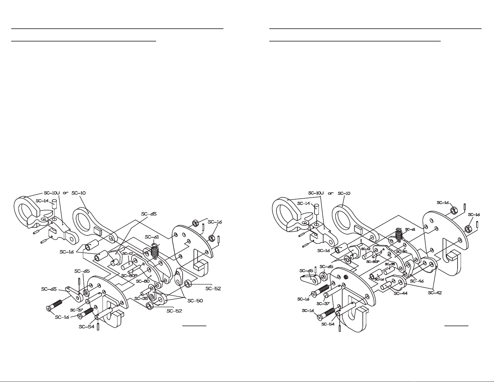
5. Inspect the gripping cam(s) (SC-50 or SC-42, Fig. 7) for wear and
defects. Gripping surfaces must be sharp and free of foreign matter.
6. Inspect the condition of the body for wear, damage and distortion,
particularly in the area of the jaw opening and holes for pins.
7. Inspect the lifting shackle (SC-10, Fig. 7) and all pins for wear and
damage.
8. The lock spring (SC-61, Fig. 7) must have a definite amount of tension
when the lock is moved to the lock closed position, with minimal
material in the clamp.
9. Remove from service and tag any clamp in need of repair indicating
the problem area and bring to supervisor’s attention. A full periodic
inspection is to be performed at this time by qualified personnel (see
periodic inspection, p. 9). The next periodic inspection will be timed
from when the clamp is returned to service.
10. Make sure that all roll pins are securely in place.
11. Never use a clamp in need of repair.
3
Safety Clamps, Inc. Model VL-Channel

OPERATION
Loading the clamp
1. When placing the clamp onto the material, the clamp should be in the
locked open position with the gripping cam(s) out of the jaw opening.
This helps to prevent damage to the gripping teeth during loading.
2. Center the clamp so the load is balanced when lifted. When using
more than one clamp, make sure the clamps are positioned to share
equal loads.
3 For a clamp with a standard lifting shackle (SC-10), make sure the
clamp is positioned so the direction of force applied by the crane is in
line with the lifting shackle (Fig. 3).
WARNING: Never exceed 10° side loading with a VL-Channel
clamp with a standard Lifting Shackle (Fig. 3).
4. Place the jaw of the clamp around the material to be lifted. Make sure
the clamp is positioned so the bulb profile or angle flange are against
the front side of the relief area of the jaw.
5. Secure the clamp in the locked closed position. Do this by rotating the
lock handle (A, Fig. 5) until the lock inside the body is positioned
against the stop (B, Fig. 5). The gripping cam(s) (C, Fig. 5) will rotate
into the jaw and engage the material. Ensure the clamp is fully
engaged with the material.
6. Once the clamp is properly locked closed onto the material, the clamp
is now ready to make a lift.
WARNING: The operator and all other personnel should be fully
clear of the lifting area.
Safety Clamps, Inc. Model VL-Channel
4Figure 4: Locked Open Figure 5: Locked Closed
OPERATION
Lift and Transfer of Material
1. As the operator begins to make the lift, ensure the load is balanced.
If the load is not balanced, lower the material and adjust the position
of the clamp(s) accordingly and follow the guidelines under the
“Loading the clamp” section. Never lift or transfer material when the
load is not balanced.
2. During transfer of the material from one location to another, the
operator should ensure the load is steady during transfer and not
allow the load to bump or strike other objects.
3 Upon reaching the material’s destination, lower the clamp and material
to a secure position until the tension is relieved on the lifting shackle
(E, Fig. 4).
4. Once the load is at rest and secured, rotate the lock handle (A, Fig. 4)
to the locked open position. This will disengage the clamp from the
material and lock the gripping cam(s) (C, Fig. 4) out of the jaw opening
to protect the gripping teeth. If the clamp is in a hard to reach position,
push in on the lifting shackle (E, Fig. 4) after the lock handle (A, Fig. 4)
is released to help facilitate locking the clamp open.
Note: Always store the clamp in the locked open position to
protect the grippers and help ensure longer use.
Warning
Operator must follow all guidelines in each section before making a lift.
5
Safety Clamps, Inc. Model VL-Channel
Figure 6: The rated capacity of a clamp with the Universal Lifting Shackle decreases
as the angle of side load increases.
Angle of Side Load % Maximum Rated Capacity
0° to 30° = 100%
30+° to 45° = 75%
45+° to 90° = 50%

Part # Parts List for 1 ton Model VL-Channel
SC-10 Lifting Shackle
SC-10U Universal Lifting Shackle
SC-12 Lifting Shackle Connecting Pin
SC-14 Universal Lifting Shackle Pin
SC-16 Body Bolt Assembly (1 spacer, bolt, & nut)
SC-35 Connecting Yoke-Cam Link Pin
SC-37 Connecting Yoke Body Pin with roll pin
SC-50 Gripping Cam Assembly (SC-42, SC-44, (2) SC-46)
SC-52 Gripping Cam Spacers
SC-54 Gripping Cam Body Pin with (2) roll pins
SC-61 Lock Spring
SC-65 Lock Handle Assembly - includes Lock, Handle, Handle Spacer,
(1) roll pin for handle & lock, (1) retainer roll pin for lock spring
SC-80 Connecting Yokes (pair) and spring connector pin (SC-80P)
Safety Clamps, Inc. Model VL-Channel
Figure 7
6
Part # Parts List for 2 ton and 4 ton Model VL-Channel
SC-10 Lifting Shackle
SC-10U Universal Lifting Shackle
SC-12 Lifting Shackle Connecting Pin
SC-14 Universal Lifting Shackle Pin
SC-16 Body Bolt Assembly (1 spacer, bolt, & nut)
SC-35 Connecting Yoke-Cam Link Pin
SC-37 Connecting Yoke Body Pin with roll pin
SC-42 Gripping Cams (pair)
SC-44 Gripping Cam-Link Pin
SC-54 Gripping Cam Body Pin with (2) roll pins
SC-61 Lock Spring
SC-65 Lock Handle Assembly - includes Lock, Lock Shim, Handle,
Handle Spacer, (1) roll pin for handle & lock, (1) retainer
roll pin for lock spring
SC-80 Connecting Yokes (pair) and spring connector pin (SC-80P)
Safety Clamps, Inc. Model VL-Channel
Figure 7
7
Table of contents
Other SC Safety Equipment manuals
Popular Safety Equipment manuals by other brands

Lanex
Lanex PB-20 instruction manual

SKYLOTEC
SKYLOTEC ANCHOR ROPES Instructions for use

Besto
Besto Buoyancy Aid 50N Instructions for use

TEUFELBERGER
TEUFELBERGER NODUS Manufacturer's information and instructions for use

Troy Lee Designs
Troy Lee Designs Tbone Product owners manual

Innova
Innova Xtirpa Instruction and safety manual

bolle SAFETY
bolle SAFETY B810 quick start guide

SHENZHEN FANHAI SANJIANG ELECTRONICS
SHENZHEN FANHAI SANJIANG ELECTRONICS A9060T instruction manual

Hiltron security
Hiltron security POWER8E Installation and use manual

Salewa
Salewa MTN SPIKE user manual

Hatco
Hatco B-950P installation guide

Sitec
Sitec TX MATIC operating manual