SC VL Series Operating instructions

Operation, Maintenance and
Repair Manual for
VL Series Clamps
The VL Series includes models:
Safety clamps, inc.
Home of the “big Bite” Lifting Clamp
VL
VLC
VL-SJ
VLX
PDS
(Also includes the listed models with
the Universal Lifting Shackle, Auxiliary Lock,
and/or Stainless Grippers)
Excludes Models VL-BC, and VL-Channel
Products manufactured by Safety Clamps, Inc.
meet and/or exceed:
ANSI/ASME B30.20/ BTH-1
Design Category: C
Service Class: 4
Warning
Prior to operating your Safety Clamp, please ensure
All operators read and understand this manual.
Effective January 1, 2018
This manual supersedes all previous VL manuals.

Serial # _______________________
Model _______________________
Max. Rated
Capacity in Tons _______________________
Jaw Opening _______________________
Safety Clamps, Inc.
Repair Service Center
Call 1-800-456-2809 for a Return AuthorizationΝumber.
Include:
Model
Rated Capacity
Serial Number
You will receive a written quote within 24 hours of receipt of your
Safety Clamp.
Your Safety Clamp will be repaired, tested, re-certified, painted, and
shipped within 24 hours of authorization.
We also perform periodic inspections and re-certifications.
It’s that easy! Call 1-800-456-2809 for more details.
Register Your Clamp
Go to www.safetyclamps.com to register your clamp to receive the most
appropriate service and product support for your clamp and new product
updates as they come available.
10 Year Limited Warranty
All products manufactured by Safety Clamps, Inc. carry a limited warranty
that the product is free from defects in materials and workmanship. This
warranty applies only to the original end user of the clamp and is valid for 10
years from the date of purchase.
Conditions
This warranty only covers defects in materials and workmanship and only if
the clamp has been inspected, maintained, and operated within the
guidelines of the clamp’s Operation, Maintenance, and Repair Manual. The
warranty does not cover wear to parts such as pins, grippers, lock springs,
etc. If a defect is found within the warranty period, the clamp will be repaired
or replaced by determination of the manufacturer.
No warranty is given due to: regular wear; incorrect use; overload;
modification of the clamp; improper maintenance and/or repair.

GENERAL INFORMATION
1. The VL series includes models:
VL
VLC
VL
VLX
PDS
2. Always choose the proper clamp and rated capacity for the material to
be lifted.
3. The VL series Safety Clamps are designed for lifting, turning, and
transferring of steel plate, sheet, and/or structural shapes.
4. The VL series clamps may be used to lift material from a vertical
position (Fig. 1) or from horizontal to vertical to horizontal through
a 180° arc (Fig. 2).
Note: The optional auxiliary push button lock is not required to rotate
material through a 180° arc.
5. The VL series models are rated to lift material with a hardness up to
450 Brinell (48 Rockwell C).
6. For VL series models, the minimum rated capacity is 10% of the
maximum rated capacity of the clamp.
7. Remote release is standard on all locking models except models with
an auxiliary push button lock handle.
8. The operator must read and understand the Operator’s Manual before
using a Safety Clamp.
Safety Clamps, Inc. VL Series Clamps
1
Figure 1 Figure 2

Safety Clamps, Inc. VL Series Clamps
2
OPERATING AIDS
1. The VL series clamps should not be used to handle material with
temperatures below 0° F or above 225° F. These temperature
restrictions apply to both the ambient temperature and the
temperature of the material to be lifted.
2. Do not use the VL series clamps for horizontal transfer of materials.
3. Do not use clamps on materials with a hardness in excess of
450 Brinell (48 Rockwell C).
4. Do not lift plate with mill scale, grease, or any other coatings that may
prevent gripping surface from making solid contact with plate.
5. Do not lift material from the side with a VL series clamp (Fig. 4) unless
using a clamp with the Universal Lifting Shackle.
Note: As the angle of side load increases, the rated
capacity decreases (Fig. 5).
6. Never exceed ten degrees (10°) side load with a VL series clamp that
has a standard lifting shackle (Fig. 3).
7. Do not lift more than one plate at a time.
8. Always ensure the clamp is seated properly on the material to be
lifted. Place the gripping pad (D, Fig. 7) against the material
when locking the clamp closed to ensure the rotating gripping cam(s)
(C, Fig. 7) contact the material in the position they will make the lift.
9. Make sure the load to be lifted is properly balanced. Multiple clamps
may be needed to balance the load.
10. Never lift or transfer material over or near people.
11. Always lock the clamp closed before making a lift. Don’t make a lift
with the lock in the open or “locked open” position.
12. Do not lift clamp with an open-end hook.
13. Do not alter clamp. Do not weld, grind, or modify the clamp in any way.
14. If a clamp has been overloaded or damaged in any way, take the
clamp out of service immediately.
15. Do not improvise and misuse the clamp. Always use correct clamp for
the lift.
16. For VL series models, the minimum rated capacity is 10% of the
maximum rated capacity of the clamp. The minimum rated capacity
ensures the load is not too light for the clamp to properly bite into the
material.

Safety Clamps, Inc. VL Series Clamps
3
Figure 3: Never exceed 10° side loading with a VL series clamp unless using a
clamp with a Universal Lifting Shackle. When using a clamp with a standard shackle,
always position the clamp so the direction of force applied by the crane is in line with
the lifting shackle.
45°
MAX.
Never
Max 10000100Max
Yes Yes
Figure 4: Never lift material from the side with a “VL” series clamp unless using a
clamp with the Universal Lifting Shackle.
Universal
Shackle
Yes
Standard
Shackle
Never
0°
30° 30°
45°
90°
45°
90°
100% 75%
75%
50%
50%
Figure 5: The rated capacity of a clamp with the Universal Lifting Shackle decreases
as the angle of side load increases.
Angle of Side Load % Maximum Rated Capacity
0° to 30° = 100%
30+° to 45° = 75%
45+° to 90° = 50%

OPERATION
Inspection Before and After Each Use
The Safety Clamps inspection procedures meet and/or exceed the
requirements set forth in the ASME B30.20 Below-the-Hook Lifting Devices
guideline.
1. Before using any Safety Clamp, the operator must read and understand
the Operator’s Manual in its entirety.
2. All Safety Clamps should be inspected before and after each use.
Do not use if any components are bent, elongated, gouged, nicked
excessively, worn, and/or damaged. Make sure that nuts, bolts, pins,
and other mechanical fasteners are tightened and secured.
3. Be sure the clamp to be used is the proper clamp for the job. Check
the rated capacity and jaw opening stenciled on the Identification Tag.
Both should equal or exceed the requirements for the load to be lifted.
4. For VL series models, the minimum rated capacity is 10% of the
maximum rated capacity of the clamp. The minimum rated capacity
ensures the load is not too light for the clamp to properly bite into the
material.
Warning: Never exceed the rated capacity or use on material that
is not within jaw range of the clamp. Never lift material that does
not meet the minimum rated capacity of the clamp.
5. Do not use the clamp if the Identification Tag or the Warning Tag is
missing or illegible.
6. Inspect the gripping cam(s) (SC-50 or SC-42, Fig. 8) and gripping pad
(SC-70, Fig. 8) for wear and defects. Gripping surfaces must be sharp
and free of foreign matter.
7. Inspect the condition of the body for wear, damage and distortion,
particularly in the area of the jaw opening and holes for pins.
8. Inspect the lifting shackle (SC-10, Fig. 8) and all pins for wear and
damage.
9. The lock spring (SC-61, Fig. 8) must have a definite amount of tension
when the lock is moved to the “Lock Closed” position, with minimal
material in the clamp. Note: Do not allow the gripping cam(s) to come
into contact with the gripping pad as this may cause damage to the
gripping edges.
4
Safety Clamps, Inc. VL Series Clamps

OPERATION
Inspection Before and After Each Use
10. For clamps with the auxiliary push-button locking handle, the lock
button in the auxiliary lock body bolt (SC-16Aux, Fig. 8) must have a
positive spring action to project it out and engage the lock handle
when the handle is moved to the “Lock Closed” position.
11. Remove from service and tag any clamp in need of repair indicating
the problem area and bring to supervisor’s attention. A full periodic
inspection is to be performed at this time by qualified personnel (see
periodic inspection, p. 11). The next periodic inspection will be timed
from when the clamp is returned to service.
12. Make sure that all roll pins are securely in place.
13. Never use a clamp in need of repair.
OPERATING AIDS
1. Do not use the VL series clamps for horizontal transfer of materials.
2. Do not use clamps on materials with a hardness in excess of
450 Brinell (48 Rockwell C).
3. Do not lift plate with mill scale, grease, or any other coatings that may
prevent gripping surface from making solid contact with plate.
4. Never exceed ten degrees (10°) side load with a VL series clamp that
has a standard lifting shackle (Fig. 3).
5. Do not lift more than one plate at a time.
6. Always ensure the clamp is seated properly on the material to be
lifted. Place the gripping pad (D, Fig. 6 & 7) against the material
when locking the clamp closed to ensure the rotating gripping cam(s)
(C, Fig. 7) contact the material in the position they will make the lift.
7. Make sure the load to be lifted is properly balanced. Multiple clamps
may be needed to balance the load.
8. If a clamp has been overloaded or damaged in any way, take the
clamp out of service immediately.
9. Do not improvise and misuse the clamp. Always use correct clamp for
the lift.
10. For VL series models, the minimum rated capacity is 10% of the
maximum rated capacity of the clamp.
5
Safety Clamps, Inc. VL Series Clamps

OPERATION
Loading the clamp
1. When placing the clamp onto the material, the clamp should be in the
“locked open” or open position with the gripping cam(s) out of the jaw
opening. This helps to prevent damage to the gripping teeth during
loading.
2. Center the clamp so the load is balanced when lifted. When using
more than one clamp, make sure the clamps are positioned to share
equal loads.
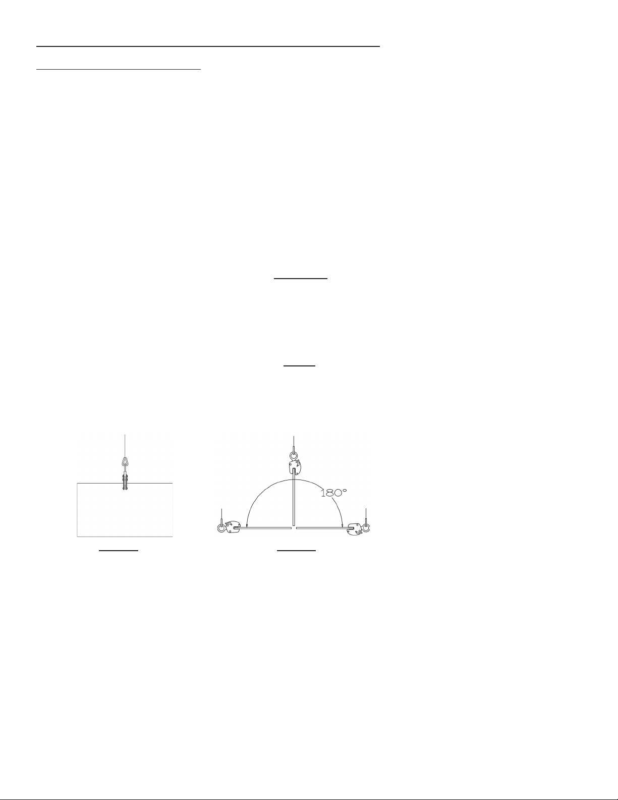
3 For a clamp with a standard lifting shackle (SC-10), make sure the
clamp is positioned so the direction of force applied by the crane is in
line with the lifting shackle (Fig. 3).
WARNING: Never exceed 10° side loading with a VL series clamp
with a standard Lifting Shackle (Fig. 3).
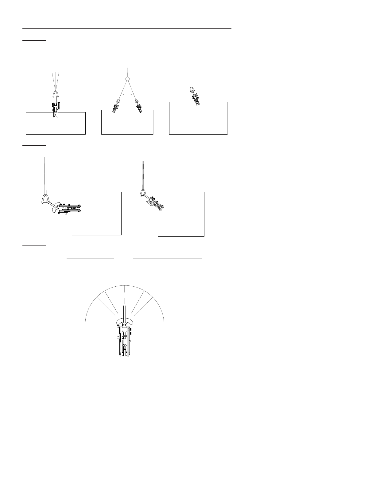
4. Place the jaw of the clamp around the material to be lifted. Make sure
the clamp is positioned so the edge of the material is 1/8” to 1/4” from
the back of jaw opening and the gripping surfaces are in full contact
with the material. When lifting from a horizontal position, our unique
design allows the operator to load the clamp with the gripping pad
(D, Fig. 7) below the plate or on top of the plate.
5. Secure the clamp in the “locked closed” position. Do this by seating
the clamp on the material with the gripping pad (D, Fig. 6) against the
material and rotating the lock handle (A, Fig. 7) until the lock inside
the body is positioned against the stop (B, Fig. 7). The gripping cam(s)
(C, Fig. 7) will rotate into the jaw and engage the material at the point
where they will bite into the material once the lift is started.
Note: When using a clamp with the auxiliary push-button lock handle,
ensure the auxiliary lock is fully engaged and the spring-loaded push
button on the handle is flush with the push-button retainer ring.
WARNING: Not properly seating the clamp may cause the clamp
to slide on the material once the lift begins. Always ensure the
grippers are seated properly. Check this by pushing away on the
clamp body as you pull back on the lifting shackle (E, Fig. 7) and
look to ensure the gripping cam(s) and gripping pad are engaging
the material.
6. Once the clamp is properly locked closed onto the material, the clamp
is now ready to make a lift.
WARNING: The operator and all other personnel should be fully
clear of the lifting area.
Safety Clamps, Inc. VL Series Clamps
6

E
A
C
D
B
OPERATION
Lift and Transfer of Material
1. As the operator begins to make the lift, ensure the load is balanced.
If the load is not balanced, lower the material and adjust the position
of the clamps accordingly and follow the guidelines under the “Loading
the clamp” section. Never lift or transfer material when the load is not
balanced.
2. During transfer of the material from one location to another, the
operator should ensure the load is steady during transfer and not
allow the load to bump or strike other objects.
3 Upon reaching the material’s destination, lower the clamp and material
to a secure position until the tension is relieved on the lifting shackle
(E, Fig. 6).
4. Once the load is at rest and secured, rotate the lock handle (A, Fig. 6)
to the “locked open” position or for VLC & AVLC the open position. This
will disengage the clamp from the material and for lock open models
will lock the gripping cam(s) (C, Fig. 6) out of the jaw opening to
protect the gripping teeth. If the clamp is in a hard to reach position,
push in on the lifting shackle (E, Fig. 6) after the lock handle (A, Fig. 6)
is released to help facilitate locking the clamp open.
Note: For lock open models always store the clamp in the “locked
open” position to protect the grippers and help ensure longer use.
If the clamp is not locked open it can allow the grippers to strike each
other, possibly causing damage to the gripping teeth/edges. For
VLC and AVLC models, do not allow the gripping cams to strike the
gripping pad. Slowly lower the gripping cams into the jaw when the
clamp is not in use.
Warning
Operator must follow all guidelines in each section before making a lift.
7
Safety Clamps, Inc. VL Series Clamps
Figure 6: “Locked Open” /
Open Position Figure 7: “Locked Closed”
E
A
C
D
B

Part # Parts List for VL Series Models 1/2 ton & 1 ton, & 2 ton VL-SJ
SC-10 Lifting Shackle
SC-10U Universal Lifting Shackle
SC-12 Lifting Shackle Pin
SC-14 Universal Lifting Shackle Pin
SC-16 Body Bolt Assembly (1 spacer, bolt, & nut)
SC-16AUX Body Bolt Assembly for Auxiliary Lock (1 spacer, bolt, & nut)
SC-35 Connecting Yoke-Cam Link Pin
SC-37 Connecting Yoke Body Pin with roll pin
SC-50 Gripping Cam Assembly (SC-42, SC-44, (2) SC-46)
SC-50ST Stainless Gripping Cam Assembly
SC-52 Gripping Cam Spacers
SC-54 Gripping Cam Body Pin with (2) roll pins
SC-61 Lock Spring
SC-65 Lock Handle Assembly - includes Lock, Handle, Handle Spacer,
(1) roll pin for handle & lock, (1) retainer roll pin for lock spring
SC-66 Auxiliary Lock Handle Assembly - includes Lock,
Lock Handle with push button, and Lock Handle Spacer
SC-70 Gripping Pad with bolt and locknut
SC-70ST Stainless Gripping Pad with bolt and locknut
SC-80 Connecting Yokes (pair) and spring connector pin
Safety Clamps, Inc. VL Series Clamps
Figure 8
8

Part # Parts List for VL Series Models 2 - 20 ton, except 2 ton VL-SJ
SC-10 Lifting Shackle
SC-10U Universal Lifting Shackle
SC-12 Lifting Shackle Pin
SC-14 Universal Lifting Shackle Pin
SC-16 Body Bolt Assembly (1 spacer, bolt, & nut)
SC-16AUX Body Bolt Assembly for Auxiliary Lock (1 spacer, bolt, & nut)
SC-35 Connecting Yoke-Cam Link Pin
SC-37 Connecting Yoke Body Pin with roll pin
SC-42 Gripping Cams (pair)
SC-42ST Stainless Gripping Cams (pair)
SC-44 Gripping Cam-Link Pin
SC-54 Gripping Cam Body Pin with (2) roll pins
SC-61 Lock Spring
SC-65 Lock Handle Assembly - includes Lock, Lock Shim, Handle,
Handle Spacer, (1) roll pin for handle & lock, (1) retainer
roll pin for lock spring
SC-66 Auxiliary Lock Handle Assembly - includes Lock, Lock Shim,
Lock Handle with push button, Lock Handle Spacer, (1) roll pin for
handle & lock, (1) retainer roll pin for lock spring
SC-70 Gripping Pad with bolt and locknut
SC-70ST Stainless Gripping Pad with bolt and locknut
SC-80 Connecting Yokes (pair) and spring connector pin
Safety Clamps, Inc. VL Series Clamps
Figure 8
9

INSPECTION AND MAINTENANCE
The Safety Clamps Inspection and Maintenance schedule and procedures
meet and/or exceed the requirements set forth in the ASME B30.20
Below-the-Hook Lifting Devices guideline. The severity of service the clamp
is subjected to will determine the frequency and type of inspection required
for the clamp and will be determined by the clamp owner.
Inspection Before and After Each Use
1. Before using any Safety Clamp, the operator must read and understand
the Operator’s Manual in its entirety.
2. All Safety Clamps should be inspected before and after each use.
Do not use if any components are bent, elongated, gouged, nicked
excessively, worn, and/or damaged. Make sure that nuts, bolts, pins,
and other mechanical fasteners are tightened and secure.
3. Be sure the clamp to be used is the proper clamp for the job. Check
the rated capacity and jaw opening stenciled on the Identification Tag.
Both should equal or exceed the requirements for the load to be lifted.
4. For VL series models, the minimum rated capacity is 10% of the
maximum rated capacity of the clamp. The minimum rated capacity
ensures the load is not too light for the clamp to properly bite into the
material.
Warning: Never exceed the rated capacity or use on material that
is not within jaw range of the clamp. Never lift material that does
not meet the minimum rated capacity of the clamp.
5. Do not use the clamp if the Identification Tag or the Warning Tag is
missing or illegible.
6. Inspect the gripping cam(s) (SC-50 or SC-42, Fig. 8) and gripping pad
(SC-70, Fig. 8) for wear and defects. Gripping surfaces must be sharp
and free of foreign matter.
7. Inspect condition of body for wear, damage and distortion, particularly
in the area of the jaw opening and holes for pins.
8. Inspect the lifting shackle (SC-10, Fig. 8) and all pins for wear and
damage.
9. The lock spring (SC-61, Fig. 8) must have a definite amount of tension
when the lock is moved to the “Lock Closed” position, with minimal
material in the clamp. Note: Do not allow the gripping cam(s) to come
into contact with the gripping pad as this may cause damage to the
gripping edges.
Safety Clamps, Inc. VL Series Clamps
10

INSPECTION AND MAINTENANCE
10. For clamps with the auxiliary push-button locking handle, the lock
button in the auxiliary lock body bolt (SC-16Aux, Fig. 8) must have a
positive spring action to project it out and engage the lock handle
when the handle is moved to the “Lock Closed” position.
11. Remove from service and tag any clamp in need of repair indicating
the problem area and bring to supervisor’s attention. A full periodic
inspection is to be performed at this time by qualified personnel. The
next periodic inspection will be timed from when the clamp is returned
to service.
12. Make sure that all roll pins are securely in place.
13. Never use a clamp in need of repair.
Periodic Inspection
A periodic inspection is to be performed by qualified personnel. The
inspection will be performed based on the level of service of the clamp:
Normal Service: Annual Inspection
Heavy Service: Semi-Annual Inspection
Severe Service: Quarterly
1. Verify and record the model, rated capacity, jaw opening, and
serial number of the clamp which is stenciled on the Identification
Tag. If the tag is missing or not legible, the serial number is stamped
into the body of the clamp, typically under the gripping pad seat.
Contact Safety Clamps, Inc. and we can identify your clamp and issue
an RGA number to return the clamp to us. We will replace the
Identification Tag at no charge.
2. Completely disassemble the clamp. Disassembly directions are on
page 15.
3 Remove all dirt, grease, and other foreign matter that may inhibit
proper inspection of the clamp body or clamp components.
4. Clamp Body Inspection
a.) Inspect all welds and all internal and external surfaces for fractures,
wear, and distortion.
b.) Inspect all pin holes for wear and elongation.
c.) Inspect inside the jaw opening for displaced metal and distortion.
d.) Inspect the lock pivot holes for excessive wear.
Warning: Replace lifting clamps containing any fractures,
elongated holes, jaw opening with displaced metal, and/or
distorted jaw openings.
Safety Clamps, Inc. VL Series Clamps
11

INSPECTION AND MAINTENANCE
Periodic Inspection - cont’d
5. Lifting Shackle (SC-10, Fig. 8) Inspection
a.) Inspect the lifting eye for elongation and wear at the point where the
eye engages the sling attachment.
b.) Inspect the shackle pin hole for wear and elongation.
c.) Inspect the shackle body for bending.
d.) Universal Lifting Shackle: Inspect shackle pivot pin
(SC-14, Fig. 8) and shackle pivot pin hole for wear and distortion.
Note: An elongated shackle eye indicates overloading. An elongated
shackle pin hole indicates wear and possible overloading. A bent
shackle indicates excessive side-loading.
Warning: Replace shackles that are bent, show excessive wear,
or have elongated eye or shackle pin holes.
6. Gripping Cam (SC-50 or SC-42, Fig. 8) Inspection
a.) Inspect the gripping cam(s) for chipped or worn teeth. The teeth
must be sharp and free of foreign matter.
b.) Inspect pin holes for elongation and wear.
c.) For the SC-50, inspect the connecting arms for distortion and
fractures. Inspect the pin holes for elongation and wear. The
gripping cam should pivot freely in assembly.
Warning: Replace cam assembly (SC-50) or gripping cams
(SC-42) with worn or damaged teeth, that contain fractures, and
cams and cam arms that have elongated pin holes.
7. Gripping Cam Connecting Link (SC-46, Fig. 8) Inspection
a.) Inspect pin holes for elongation and wear.
b.) Inspect the gripping cam connecting link for distortion and
fractures.
Warning: Replace gripping cam connecting link that is distorted,
fractured, or if pin holes are worn or elongated.
8. Shackle Pin (SC-12), Connecting Cam Pin (SC-35), Connecting
Yoke Body Pin (SC-37), Gripping Cam Connecting Pin (SC-44),
and Gripping Cam Body Pin (SC-54) Inspection (Refer to Fig. 8)
a.) Inspect all pins for:
Distortion
Surface blemishes
Wear
Fractures
Warning: Replace pins that are distorted, have surface scars, are
worn, or contain fractures.
Safety Clamps, Inc. VL Series Clamps
12

INSPECTION AND MAINTENANCE
Periodic Inspection - cont’d
9. Gripper Pad (SC-70, Fig. 8) Inspection
a.) Inspect the gripper pad for fractures, damage, and wear. The
gripping edge must be sharp and free of imperfections and foreign
matter.
b.) Gripper pad must pivot freely in the clamp. During assembly, insert
lubricant in the gripping pad seat (body recess) before installing
the gripper pad. The recommended lubricant is Powdered
Graphite or Molybdenum Disulfide Grease. Tighten the screw
and lock nut to just snug, then reverse the nut one quarter turn to
allow free rotation of the gripper pad.
Warning: Replace worn, dull, or damaged gripper pad.
10. Connecting Yokes (SC-80, Fig. 8) Inspection
a.) Inspect pin holes for elongation and wear.
b.) Inspect the connecting yokes for distortion and fractures.
c.) Inspect lock ear area where the lock engages for wear. If worn the
clamp may not fully lock open with the gripping cam(s) (SC-50 or
SC-42) out of the jaw area.
Warning: Replace connecting yokes that are distorted, fractured,
if pin holes are elongated or worn, or if lock ear is worn.
11. Lock Spring (SC-61, Fig. 8) Inspection
a.) Inspect the lock spring for distortion. The lock spring must have
a definite amount of tension when the lock is moved to the “Lock
Closed” position, with minimal material in the clamp. The lock
must rest on the stop (B, Fig. 7). Do not allow the gripping cam(s)
to come into contact with the gripper pad. This may cause damage
to the gripping edges.
Warning: Replace the lock spring if it is damaged, distorted, or
lacking in spring tension.
12. Lock Assembly (SC-65, Fig. 8) Inspection
a.) Inspect the lock assembly for damage and wear. Inspect area that
engages connecting yoke (SC-80) for wear or distortion. If worn the
clamp may not fully lock open with gripping cam(s) out of the jaw.
b.) Inspect the lock assembly for binding. The lock assembly should
pivot freely. Binding indicates worn parts and/or foreign matter in
the assembly.
Warning: Replace lock assembly if any parts are worn or
damaged, fit loosely in the body hole, or do not have a definite
“Lock Closed” or “Locked Open” position. Note: AVLC and VLC
models Locks closed only.
Safety Clamps, Inc. VL Series Clamps
13

INSPECTION AND MAINTENANCE
Periodic Inspection - cont’d
13. Auxiliary Lock Assembly (SC-66, Fig. 8) Inspection
a.) Follow the inspection guidelines for the lock assembly (SC-65).
In addition:
b.) Inspect push button assembly in the lock handle for wear or
binding. If binding check for damage or foreign matter. The lock
button in the auxiliary lock body bolt (SC-16Aux) must fit
completely inside opening in lock handle when “Locked Closed”.
Warning: Replace lock assembly if any parts are worn or
damaged, fit loosely in the body hole, or do not have a definite
“Lock Closed” or “Locked Open” position.
14. Body Bolt and Body Spacer (SC-16, Fig. 8) Inspection
a.) Inspect the body bolts and body spacers for wear at the position
where the body spacer contacts the lifting shackle (SC-10, Fig. 8).
b.) Inspect the body bolts for wear or damage.
c.) When replacing body bolt, tighten nut on bolt until the nut is
securely against the clamp body & the body spacer cannot rotate.
Warning: Replace body bolt & nut and body spacer if worn or
damaged.
15. Auxiliary Body Bolt and Body Spacer (SC-16Aux) Inspection:
a.) Inspect the body bolt and body spacer for wear at the position
where the body spacer contacts the lifting shackle (SC-10, Fig. 8).
b.) Inspect the auxiliary lock button. The button must move in and out
without binding. The spring load must be sufficient to maintain the
button in the extended position.
Warning: Replace the auxiliary body bolt & nut and auxiliary body
spacer if worn or damaged.
16. Clamp Assembly Inspection
a.) After re-assembling the clamp, check the operation of the clamp.
All parts should move freely without binding. Refer to the exploded
view (Fig. 8) of the clamp for proper location of all component
parts.
Warning: All retaining pins and fasteners must be in place.
17. Maintenance Log Entry
After any work is performed on the clamp, the maintenance log book
must be updated to show verification of these repairs. The log book
will be kept and maintained by the company maintenance personnel.
Safety Clamps, Inc. VL Series Clamps
14

INSPECTION AND MAINTENANCE
Disassembly
Refer to exploded views on pages 8 and 9 for part numbers.
1. Remove roll pins for the gripping cam body pin (SC-54) and the
connecting yoke body pin (SC-37) and remove body pins.
2. Remove the lock handle assembly (SC-65).
a.) Remove the retainer pin on the lock spring shaft that keeps the
lock spring (SC-61) in position. Remove lock spring from lock.
b.) Remove the roll pin holding the lock handle to the lock’s handle
shaft. Remove handle, handle spacer, lock, and lock shim.
Note: 1/2 ton and 1 ton capacities do not have a lock shim.
3. Remove the gripping cam(s) (SC-50 or SC-42).
4. Grasp the lifting shackle (SC-10) and pull remaining parts (inside
assembly) out of the back of the clamp between the body bolts.
5. Remove the remaining pins from the inside assembly and separate the
parts making note of part numbers.
6. To disassemble the Universal Lifting Shackle (SC-10U) remove the roll
pins and remove the Universal Lifting Shackle Pin (SC-14).
7. Remove the gripping pad (SC-70) by removing the lock nut on the
retaining screw.
Warning
Do Not:
Do not fix, straighten, or heat treat the clamp body or any clamp parts.
Do not modify, weld, or change the clamp body or clamp parts in any
way.
Do not use any heating methods to clean parts.
Do:
Use only Genuine Safety Clamps Parts when replacing any part on a
Safety Clamp.
Do put enough value in yourself and those around you to follow all
guidelines in this manual for the protection of everyone.
15
Safety Clamps, Inc. VL Series Clamps

Inspection and Repair Log
16
Date Inspection/Repair Performed by:

Inspection and Repair Log
Date Inspection/Repair Performed by:

Register Your Clamp
Go to www.safetyclamps.com to register your clamp to receive the most
appropriate service, product support, and training aids for your clamp
and also receive updates on new products.
10 Year Limited Warranty
See inside front cover for details.
Call, Fax, or email Us Today!
Safety Clamps, Inc. Phone 904-781-2809
233 Santa Barbara Ave. 800-456-2809
Jacksonville, FL 32254 Fax 904-786-2116
www.safetyclamps.com
Effective January 1, 2018
This manual supersedes all previous VL manuals.
Safety clamps, inc.
Home of the “big Bite” Lifting Clamp
This manual suits for next models
5
Table of contents
Other SC Safety Equipment manuals