Scanmar International Pelagic Autopilot User manual

Pelagic Autopilot
Installation and User Guide
Version 10.2.53
January 2020
Scanmar International, Inc.
14138 Washington Avenue
San Leandro, CA 94578
Phone 510.215.2010
www.ScanmarInternational.com

Revisions
•Ver 0.5: Added wind mode description of operation.
•Ver 0.6: Added Tiller Actuator mounting dimensions.
•Ver .91: Enhanced install instructions and photos.
•Ver .92: Added instructions for software update.
•Ver .93: Corrected software reload instructions.
•Ver .94: Updated with new motor control connections.
•Ver .96: Update of button control diagrams, motor drive connections.
•Ver .97: Revised images.
•Ver .98: Standby display revised, compass linearization calibration added. Wind mode improved. NMEA input enhanced to handle early NMEA
versions.
•Ver .981: Clarified tiller mount dimensions.
•Ver .982: Updated photos of connections.
•Ver .984: Corrected compass orientation page.
•Ver .985: Corrected standby RED LED sequence to reflect code changes.
•Ver .986: Fixed slide with gain adjust enable error.
•Ver .987: Updated motor drive connection slide.
•Ver .988: Updated calibration, adjustment, orientation slide to show new button control.
•Added Helm Not Responding section

Revisions (continued)
Ver .989 Added Monitor windvane slides showing attachment kit.
Ver .989d Corrected rudder sensor slide language.
Ver .989f Added software upgrade documentation.
Ver 989g: Enhanced software upgrade instructions. Added Monitor revised bracket photos and instructions for assembly.
Ver 989h: Description of new Monitor windvane actuator attachment kit.
Ver 989i: Improved description of parameter adjustments.
Ver 989i: Added photo of Monitor gear set attachment. Marked ADAPT mode as obsolete. Added means of returning parameters to default settings.
Ver 989J: Added description of new dimmer control, power on reboot.

System Overview
Congratulations on the purchase of your Pelagic Autopilot. The Pelagic is a sophisticated nine (9) axis, gyro controlled autopilot designed to deliver top
performance in a variety of conditions. Advanced features allow custom tuning for optimum performance whether cruising or on the race course.
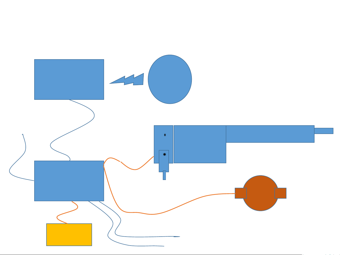
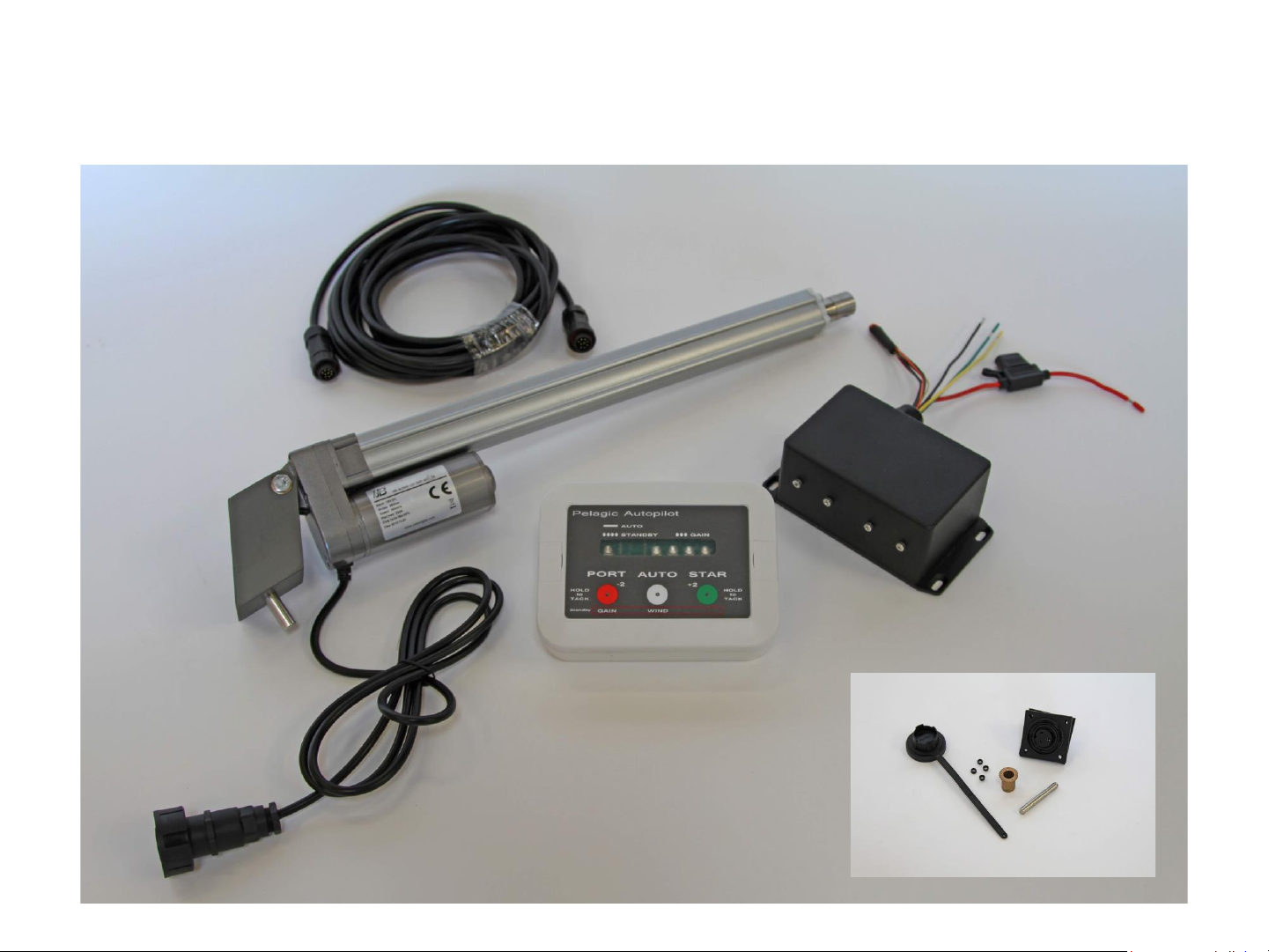
The Pelagic Autopilot is comprised of three (3) components; the Control Head, Motor Drive Box and actuator. The modular nature of the Pelagic system
allows support for many different applications including:
•Tiller steered boats (large and small)
•Use of Pelagic electronics with below decks RAMs (electrical or hydraulic)
•Use of Pelagic actuators with other manufacturer’s obsolete electronics
•Use with popular windvanes, including the Monitor and Aries.
The Control Head provides the autopilot control functions and is typically mounted in or adjacent to the cockpit. As the Control Head contains the
electronic compass and gyro sensor, it needs to be located a minimum of 6” from metal objects, including the deck compass. The unit also has an
internal USB port to receive software updates. There are two (2) important concepts that need to be understood when installing and using the Pelagic;
Orientation and Calibration.
•Orientation –This is the process of orientating the Pelagic sensors. Because the Pelagic uses a gyro sensor(s), it needs to be oriented
correctly so that as the boat pitches and rolls the feedback to the rudder is in the appropriate direction. Orientation is specified at time of
ordering and preset at the factory. While Orientation can be changed in the onboard by the user, it’s important to install the unit as
ordered or change the Orientation prior to use.
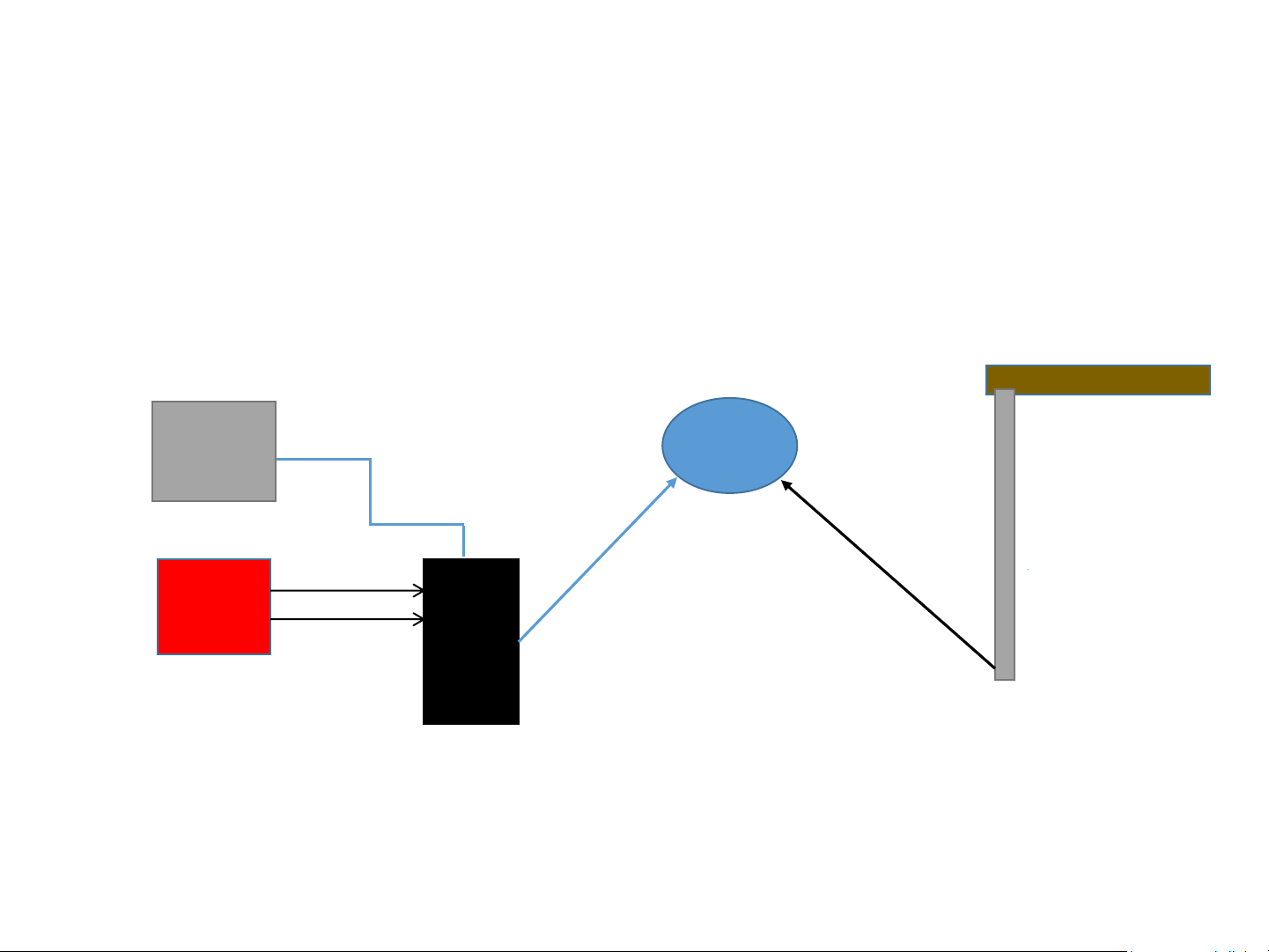
•Stern facing example –Control Head is mounted on bulkhead with control buttons facing aft (see below)
•Bow facing example –Control Head is mounted on transom with control buttons facing forward
•Port or Starboard facing are also available options
•Calibration –This is the process of calibrating the compass. Initial calibration is performed at the factory and there is no need to recalibrate
onboard unless the boat puts out strong magnetic interference.
•The Motor drive box provides power to the Pelagic system and should be installed below decks out of the elements. Two versions of the Motor
drive box are available; a standard version for the Pelagic actuators and a heavy electronics version to meet the demands of large actuators and
below decks drives.
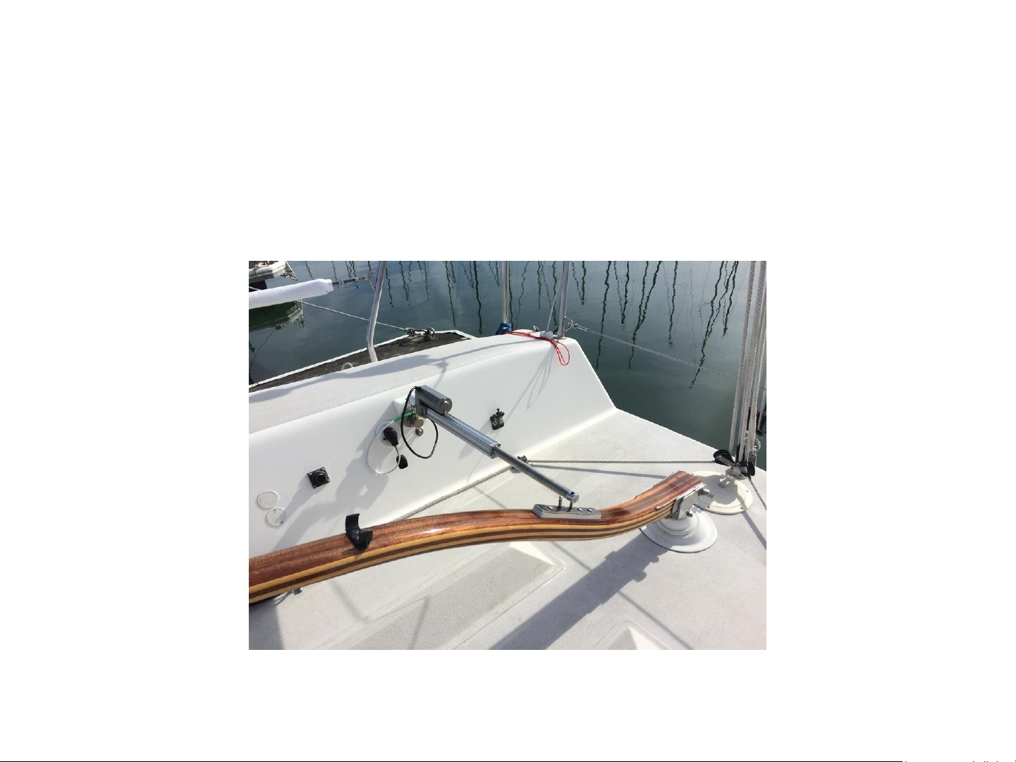
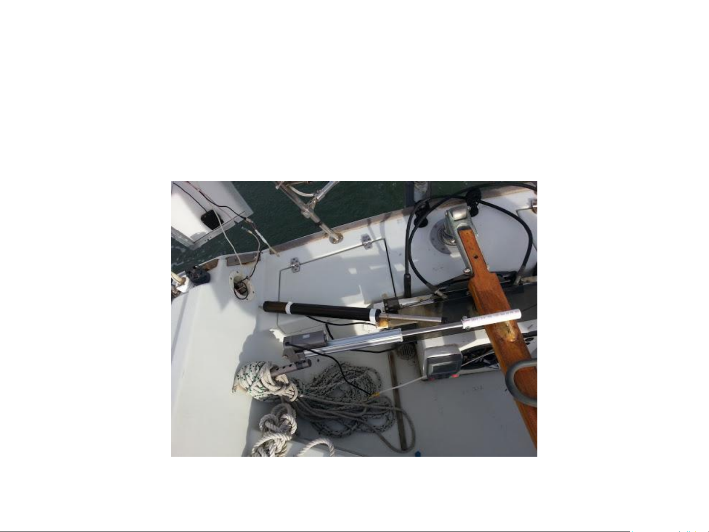
•The Pelagic actuators are designed to steer small to mid-displacement vessels, by direct attachment to the tiller or windvane. The actuators are
ruggedized to provide longer service life.
Typical Stern Facing Installation

System Features
•Controls most 12 volt steering systems
•Tiller wands & wheel steering systems
•Windvane steering control (low power)
•Hydraulic actuators
•Linear actuators above and below deck.
•Internal electronic tilt compensated
compass
•Gyro controlled steering
•Wind following via NMEA0183
•Optional RF (wireless) Remote control
•9 Sensor feedback sea state and
enable internal compass + gyro
steering
•Software uprgradable
•Adaptive adjustment for sea state to
minimize power
•No rudder sensor required
•Motor stall detection and power
reduction
•Automatic stall retry
•User calibration of key parameters
•Low power in standby: less than 0.1
amps
•No battery voltage boost module
necessary, operates as low as 9 volts
DC (actuator reduced power)
•Housings are IP67 rated

The Pelagic System –Tiller, Quadrant,
Wheel, or Windvane
Pelagic Components in blue
Control Head &
Gyro/Compass
Enclosure
Motor Electronics
Enclosure
Actuator
12 V
Battery
Below deck Linear &
Hydraulic Drives. Wheel drives
Wireless
Remote
NMEA0183
Wind Option
3 Wire Rudder Sensor Option
Mount above or
below deck
12V
Motor
or Hydr.
Pump
Two wire,
high current
Two wire,
high current
Clutch
Tiller Drive Actuators

Typical Tiller Pilot System Layout
12V
Battery
Pelagic
Motor
Drive
Typically
Installed
Below deck
Bulgin
Deck
Outlet
Pelagic
Controller
Typically Installed
Above deck
Tiller
T
A
c
t
u
a
t
o
r
+/-
20’ control cable
with twist lock
connectors
Customer supplied wiring to
Deck connector 1m max
5’ (1.5m)
2 wire
cable

Tiller Wand Installation on J92
“Rag Time”

The Pelagic is Capable of Driving Hydraulics and a
Variety of Linear Motors for Tiller or Quadrant
Testing of various
actuators

System Components for Tiller Steering

The System Controller
Provides the user interface for operation of the
autopilot. Connects to motor drive box via the data
cable.
•IP-67 rated enclosure for above deck installation
•Contains 9 attitude sensors and compass
implementation
•White: Standby / Autopilot Mode
•Red: Adjust course -2°
•Green: Adjust course +2°
•Course adjustments of 10° and 25° are enabled using
the remote control
•Gain Adjustment (Responsiveness)
•Calibration
•Orientation
•Advanced Settings
•Optional Wireless Remote Control
Contains 9 attitude sensors.
Implements a compass
•Internal USB port for system updates

The Motor Drive Box
Provides electrical connections for operation
of the autopilot. Connects to the Controller via
the data cable.
•Installed below deck
•Inline fuse
•Connections to actuator or a below decks
systems motor (depending on configuration)
•Clutch (below decks system)
•Rudder sensor (below decks system
•NMEA 0183 interface for wind data

The Linear Actuator
•Ruggedized construction
•Attaches to tiller 18” (457mm)
forward of rudder axis
•Deck mount 24 7/16” (621mm) from
tiller
•Extensions available
•Tiller pin = 1/4” stainless
•Fixed pin = 0.375” into brass socket
•Connects to Bulgin deck socket
•To extend the life of the actuator,
consider placing a Sunbrella sleeve or
plastic bag over the unit when at sea
or not in use

The Actuator Mounting Bracket Is
Reversible and Rotatable 90°
Allows rotation of motor position, up or down
Articulates in one dimension to allow tiller motion

Water Resistant Wireless Remote
Starboard 2°
Push A+B simultaneously
To engage or disengage
Autopilot steering
Port 2°
Moves rudder
10° or 25°
•See Summary of RF Remote Operation for detailed instructions
•Buttons Sealed with Polymer Panel under Keys
•Easy Battery Replacement

Autopilot System Components for
Windvane Steering
Actuator shown is
for windvane control.

Small Linear Actuator
for Windvane Steering
•Connects to the windvane
•Clamps to the 3” tube and the 1”
wind paddle tube.
•Ball and socket joints retain
actuator at both ends.
•Ball and socket joints have small
retaining springs on outside that
swing out to remove or lock the
connections.
•Put large end up to help prevent
water intrusion when in use.
•As a precaution, consider placing
a Sunbrella sleeve or plastic bag
over the unit when at sea or if
not in use.

Installation Procedure For Above
Deck Tiller System

Typical Tiller System Layout
12V
Battery
Pelagic
Motor
Drive
Typically
installed
Below decks
Bulgin
Deck
Outlet
Pelagic
Controller
Typically installed
above deck
Stern or Bow Facing
Tiller
T
A
c
t
u
a
t
o
r
+/-
20’ control cable
with twist lock
connectors
Customer supplied wiring to
deck connector 2m max length
5’ (1.5m)
2 –wire
cable

Material Required for Tiller Installation
•Two (2) #8 mounting screws or nuts/bolts for mounting the
Motor Drive box
•Two (2) #8 mounting screws or nuts/bolts for mounting the
Control head
•Wire, #16 gauge or larger to connect from the Motor Drive box
to:
•The breaker/fuse on the vessel’s 12V power distribution panel (2 wires)
•The deck outlet for tiller actuator (2 wires)
•Optional Wind Data connection (2 wires)
For a clean installation, we recommend maintaining the color code
of the wires coming off the Drive Box as shown on the Drive Box
Connections page. For example red to +, black to -, Green and
Yellow to the deck outlet. This will assist in the installation and in
any subsequent troubleshooting.
Table of contents
Popular Marine Equipment manuals by other brands

Federal Signal Corporation
Federal Signal Corporation StreamLine LP4 Installation and service instructions

Marine Instruments
Marine Instruments M3P-T user manual

FHF
FHF Aiza AX05 manual

Zenitel
Zenitel Vingtor VSS Installation & service manual

Raymarine
Raymarine AXIOM PRO installation instructions

Selden
Selden Furlex 200 S Assembly manual

Faria Beede
Faria Beede Dual Temperature Depth Sounder owner's manual

Teledyne
Teledyne RIVERRAY Deployment guide

Vetus
Vetus EC3 Operation manual and installation instructions

Marport
Marport Trawl Explorer Quick reference guide

Furuno
Furuno Felcom 50 installation manual

Fusion
Fusion Apollo 770 Quick start manual