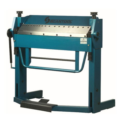
Scantool PV 30 User manual

1
Manual
SCANTOOL
Profile bending machine
PV 30
Industrivej 3-9
DK-9460 Brovst
Tel.: +45 98 23 60 88
Fax.: +45 98 23 61 44

2
EC declaration of conformity
hereby declares that
SCANTOOL Profile bending machine PV 30
are manufactured in accordance with the provisions of the European Parliament and Council
Directive 2006/42 / EC of 17 May 2006
And also in accordance with:
•Low Voltage
•EUROPEAN PARLIAMENT AND COUNCIL DIRECTIVE 2014/35 / EU of 26
February 2014
•EMC
•EUROPEAN PARLIAMENT AND COUNCIL DIRECTIVE 2014/30 / EU of 26
February 2014
SCANTOOL A/S
Industrivej 3-9
9460 Brovst
Denmark
Website: www.scantool-group.com
Ph: +45 98 23 60 88
Fax: +45 98 23 61 44

3
Table of Content
1.0 GENERAL NOTES......................................................................................................................................................4
1.1 Introductlon.............................................................................................................................................................................4
1.2 Transport.................................................................................................................................................................................5
1.3 Electrical lnformation..............................................................................................................................................................5
1.4 Maintenance............................................................................................................................................................................5
1.5 Safety ......................................................................................................................................................................................5
2.0 GENERAL SAFETY TERMS.......................................................................................................................................6
2.1 Machine's Safety Accessories and Accident Prevention Terms ..............................................................................................6
2.2 Abnormal Conditlons..............................................................................................................................................................6
3.0 PV 30 TECHNICAL PROPERTIES.............................................................................................................................7
4.0 CAPACITY CHART FOR PV 30..................................................................................................................................8
5.0 STANDARD ROLLER DIMENSIONERS FOR PV-30.................................................................................................9
6.0 TRANSPORTING, LIFTING AND CARRYING .........................................................................................................10
7.0 FOUNDATION AND MAIN DIMENSIONS OF THE MACHINE.................................................................................11
8.0 OPERATING PV 30 HORIZONTAL ..........................................................................................................................13
8.1 Materials and Products..........................................................................................................................................................15
8.2 Electrical Connection............................................................................................................................................................15
8.3 Electric Box ..........................................................................................................................................................................15
8.4 Foot Pedal.............................................................................................................................................................................16
8.5 Starting The Machine............................................................................................................................................................16
8.6 Baslc Operatlon Terms..........................................................................................................................................................16
9.0 OPERATION .............................................................................................................................................................18
9.1 Operatfng lnstructions...........................................................................................................................................................18
9.2 Operatlonal Hints..................................................................................................................................................................20
10.0 MAINTENANCE........................................................................................................................................................21
11.0 Parts listes ...............................................................................................................................................................22
11.1 Main Body Parts ...................................................................................................................................................................22
11.2 Parts and Parts List of The Main Frame................................................................................................................................23
12.0 SPECIAL ACCESSORIES FOR MODEL PV 30.......................................................................................................25
12.1 Various special rolls:.............................................................................................................................................................25
13.0 ELECTRIC SCHEMES..............................................................................................................................................27
14.0 Warranty...................................................................................................................................................................32
14.1 Guarantee..............................................................................................................................................................................32

4
1.0 GENERAL NOTES
1.1 Introductlon
This User's Manual is absolutely for your safety and is essential for the machine to have a
long production life. As long as you keep up with our Manual you will be able to run your
machine smoothly and safely. Keep in mind that the machine is designed absolute/y to
perform maximum safety and for efficient working.
In this Manual you can find instructions and information about:
1. Correct installations of the machine
2. Description of the functional parts of the machine
3. Set-up and start up adjustments
4. Correct standard and scheduled maintenance
5. Simple safety regulations and accident prevention.
Therefore, as far as the user's safety is concerned, in this handbook the possible risks
connected with machine operation are pointed out as follows:
ATTENTION: Showing the risks of accident, if instructions are not followed.
WARNING: Showing the probable damages to the machine or equipment, if the instructions
are not strictly followed.
NOTE: It gives useful information.
It is certainly necessary that the operator should read and understand all the ATTENTION
WARNING notes specified in this Manual before starting with operation of the machine and
before any lubrication or maintenance intervention.
On all steps of installation, operation and maintenance safety must be your first concern for
the protection of yourself, other users and the service of the machine.
In case of any failure please first refer to this Manual, and then if a solution cannot be found
contact first of all the distributor where you purchased our product. Do not forget to refer to
the draw in s and the numbers for an s are art needed or to define any problem. Make sure
you have the serial number and production year of the machine.
Our technical staff will make their best to help you in the most convenient way.

5
1.2 Transport
As soon as you receive the machine, check for any visible transport damages. Remove any
protective crates around the machine and read the instructions on related chapters of this
Manual carefully to set up the machine. If the machine is damaged while transport,
lmmediately take some photographs for Insurance claims.
Take precautions while loading l unloading or moving the machine to avoid any injuries. Refer
also to related chapter of this Manual for the best way of handling the machine.
1.3 Electrical lnformation
All necessary connection procedure can be found on this Manual. Do not try to connect the
machine before reading these procedures and fully understanding the drawings. Have the
machine connected by a qualified electric technician. For as we made clear in the “general
conditions of guarantee”, under no circumstances installing mistakes, one of which is the
electrical connection mistake, can be covered in the guarantee agreement. Always turn off
power before making any connections or disconnecting the machine.
1.4 Maintenance
Your machine is designed and produced to work efficiently and smoothly. To achieve this you
should also take care while operating the machine. Regard Maintenance sections to have the
longest life from your machine. Try and use original span3 parts where necessary and most
importantly do not overload the machine or do not make any unauthorized modifications.
1.5 Safety
Take all precautions possible to avoid any personal injury while using the machine. Keep in
mind to protect the third party people around the machine. Refer to safety instructions.

6
2.0 GENERAL SAFETY TERMS
2.1 Machine's Safety Accessories and Accident Prevention Terms
The machine is provided with fixed shelters for the protection of all gears. But some mobile
parts, because of their shape for the bending processing cannot be protected within a case.
However, safety is guaranteed by the machine features and by the use of "human presence"
controls.
The machine is controlled by means of foot-pushed buttons present at the downside of the
Mobile Control Panel. During operation the specified safety distance must always be
observed.
There is a red mushroom emergency button at the upside of the Mobile Control Panel to stop
all the machine activity by disabling the electric supply until released. In case of an
extraordinary situation, please push this button straight away.
No other persons except for the qualified and well trained operator should be allowed to use
the machine and to be present in the working area of the machine.
Any damaged or defective connections to the different energy supplies must be resplaced.
All interventions concerning installation, start-up, change of equipment, use, change to the
use and the operation, regular maintenance, inspection and periodical maintenance can be
performed only after disabling the machine according to relevant chapter of this handbook.
2.2 Abnormal Conditlons
In order to avoid unusual working conditions, in the following several recommendations to the
operator are listed. Also, do not forget that this machine can be used only in the conditions
presented in this operation and maintenance handbook
Before connecting the machine double-check electrical connections read the instructions
carefully. For, almost 65% of the failure resports we receive are based on either wrong
electric connection or use in contradiction to the User's Manual
Avoid the approach of persons to the operator while the machine is running.
Loading and unloading of the material should be done according to the instructions of this
handbook.
During the bending process avoid holding material with the hand.
Never wear garments with Ioose parts, which may be dragged by the machine parts, long
loosehair, necklaces, rings etc.
Never use goods except for the allowed ones as operational materials.
Never run the machine without safety devices.
Don't climb on the machine.
The machine cannot be installed and used in corrosive environments.
The machine must always be operated with one qualified operator who has the required
knowledge to use this machine properly.

7
3.0 PV 30 TECHNICAL PROPERTIES
As a superior model in its own class the PV 30 is equipped with a powerful double speed
motor and a low noise reduction gearbox, which gives the machine power to bend with ease.
The digital Read Out (optional) that can be fitted to top roll gives higher accuracy and helps
increase the efficiency. By using Mobile Control Panel that includes foot pedal and an
emergency stop you can easily and safely bend the required materials. General Technical
Information of PV 30 is given below.
STANDART SPECIFICATIONS SAFETY UNITS
Two rollers are powered Emergency Button on Mobile Control Panel
Rolls arre hardened Various DANGER signs around hardened
and
Rolls Shafts are Special Steel material grindedthe machine.
Standarcl Rolls Foot pedal control
Brake motor (Optional)
Guide Rolls Overload Circuit - Breaker
Double-Speed Motor
Horizontal and Vertical Working Position
Users manual book
SPECIAL FEATURES
Pipe l Tube Bending Rolls
Profile Bending Rolls
Angle Bending Rolls Digital Read Out
Special Lateral Angle Guides.
Note: Due to various safety regulations, the specifications presented here can change from
couniry to country without prior notice. Above dimensions and other characteristics can also
change without prior notice due to our constant improvements on our products.
Model:PV 30
Shaft Diameters
Lower Rolls Diameters
Upper Roll Diameter
Motor Rotation
Motor Power
Weight
Length
Width
Ø mm 30
Ø mm 118
Ø mm 148
rmp 1500-3000
rpm 26-12
kg 230
mm 650
mm 500
mm 1400
Height

8
4.0 CAPACITY CHART FOR PV 30
Capacities are given for ST 42 material
We reserve the right to make changes without notices.
WARNING: Do not feed profiles having a higher thickness than specified for the capacity of
the machine.
Do not feed more than one piece at a time.
Do not use the machine for any other scope the one for which it has been designed.

9
5.0 STANDARD ROLLER DIMENSIONERS FOR PV-30

10
6.0 TRANSPORTING, LIFTING AND CARRYING
Before preparing the machine for installation and stan-up,
an accurate visual control is required in order to detect any
possible damages occurred during transporting and
handling phases.
Your machine is located on a wooden grid and the
package is a waterproof plastic cover.
If one or several parts of the machine have been damaged
while shipping, the installation of the machine has to be
suspended.
While lifting take care of these points:
.Always lift and carry the machine from the handles.
.Use a steel rope capable of carrying 500 kg.
.Do not forget the Mobil Control Panel.
.Take precautions for handling and lifting.
.Check if the load is properly balanced by lifting it some centimeters.
.Lift the machine, proceeding with care, without sudden accelerations or quick changes of
directions.
.Place the machine where it must be installed, lower the machine slowly till it touches the
floor.
Figure 1: Shows a way of carrying the machine. You can use a crane with hook or a forklift
for handling operation.
Attention: Lifting and carrying operations should be carried out by skilled workers, such as
truck operator, crane operator, etc. Also, it is necessary to keep in mind that having large
safety margins will provide you efficient working conditions and enable you to take into
consideration most of the precautions.

11
7.0 FOUNDATION AND MAIN DIMENSIONS OF THE MACHINE
For a good operation, the machine needs to be bolted to the floor with anchor bolts as shown
in figure 1. However, not being high operational speeds, there is no necessity to use technical
devices to reduce the transmission of vibrations.
For a correct operation the machine must be placed on a flat, preferably concrete base and
even floor.
Figure 2 and 3 show the main dimensions of the machine. Figure 4 shows the area into which
anyone except for the operator is forbidden to enter.

12

13
Note: The manufacturer doesn't accept any responsibility for damages due to the non®
observance of the above specifications.
Note: All of machines must adjust goodly and carefully to fake smooth working from machine.
Machine adjustment must make with water gauge. The water gauge's picture is given below.
8.0 OPERATING PV 30 HORIZONTAL
Before positioning the machine it is necessary to leave
enough working area for the proper bending operations such
as: extraction ' of the cylindrical profile, feeding of the semi
product, bending of big diameters.
If you have no alternative to install the machine in a broad
area but a low height area, then there is a solution to this
problem as shown in figure 1.
To set the machine horizontally follow these steps:
1. Dismantle the screw shown by (1)
2. Rotate the machine 90°
3. Fit the screw to the hole shown by (2)
Following figures are aspects of the machine adjusted
horizontally.
Attention: Note that in the figure 3, the area bordered by
thick line shows the forbidden zone for a second person to
enter for safety reasons.

14

15
8.1 Materials and Products
The machine is mainly steel and it is not designed for handling inflammable or detrimental
products. It is duty of the customer to check if the processed materials respond to these
requirements. Also, it is duty of the customer to check if the processed materials can be
dangerous for the operator working nearby.
When selecting the most appropriate operation material you should keep in mind those
instructions:
Material must be clean out of oil and dry.
2. Hardness value must always be same thorough the material. So, we recommend you to
buy certificated steel.
3. Parts to be bended should have smooth surface to fulfill the procession correctly and
easily.
Note: The thorough cleaning of the rolls is absolutely necessary in order to avoid possible
sliding of the prohle due to grease residues on the rolls.
8.2 Electrical Connection
Have a qualified electrician connect the machine to the electric supply. In some cases inverse
electrical connection causes the motor bum out To avoid such an undesirable event, after
having connect the machine see that the motor turns to the direction shown by arrow when
activated. Or you can check to see if the rolls are rotating to the same direction of the pedals.
That is, if the right pedal is pushed, the rolls should rotate right and if the left pedal. is
pushed, the rolls should rotate left. If the machine does not comply then inverse the electric
cables.
8.3 Electric Box
The SC-30´s electric box includes very important controls
of the machine and is also connected to the below shown
foot pedals. The keys on the electric box are shown and
explained here:
1. Electric box lock
2. Speed selector
3. Start indicator
4. Electric on indicator
5. Main switch
6. Foot pedal plug-in
7. R S-T phases plug-in
8. Electric plug-in
9. Digital connection

16
Attention: Electric box shelter must be removed only when the machine is stopped, or during
maintenance or ad justment interventions.
Warning: It is suggested to protect the main electric line from possible overloads by means
of safety switches.
8.4 Foot Pedal
The foot pedal is equipped with an “emergency but ton" which instantly stops all the mach
the electric supply until released.
8.5 Starting The Machine
Following steps will help you start the machine and get ready for the first bending operation.
See the sections identifying the necessary switches and buttons.
1. Make sure the electrical connection is correct.
2. Tum on the "main switch"
3. You will see electric on "indicator"
4. Push "start button"
5. Choose a speed from the "speed selector"
6. Use the "foot pedals" to rotate the rolls
7. Make bending
8. Use the "emergency button" on "foot pedal" to stop the machine
9. Tum ofi the "main switch"
8.6 Baslc Operatlon Terms
The SC-30 has two rolls powered and top roll idle. The lower rolls are driven by a motor and
reduction gearbox system. Top roll can be adjusted by a screw driven system to make the
bending in a wide radius range. Therefore, bending operation is simple and smooth however
requires experience for efficient working. Following recommendations will be helpful during
operation:
It is recommended that the user have basic bending information with this kind of
machines.
Making a tight bend in one pass is not possible. So you need several passes before you can
achieve a certain radius. Tihgter curves and full radii always take a lot of time.
During operation never wear garments with loose parts, which may be dragged by the

17
machine parts, long loose hair, necklaces, rings etc.
Use emergency button in case of any emergency.

18
9.0 OPERATION
9.1 Operatfng lnstructions
Place the material on the rolls flatly as shown in the
figure 1. Make sure that material is placed parallel to
the ground and touching al! three rolls at the same
time. This position is called "zero position'.
Move the upper roll down like in figure 2 and position
it to apply enough force to bend the material. Do not
apply force more than necessary. If you apply too
much force with the help of moving the upper roll
down a lot more than enough, you may deflate the
material during bending operation.
Push the foot pedal to rotate the rolls to which
direction you want (look at figure 3). To get desired
diameter value make more than one pass by
gradually lowering the upper roll after each pass.
After a pass if the diameter value is bigger than
expected, move the upper roll down to apply more
force. If the case is vice versa, than move the upper
roll to upside by making use of milimetric ruler.
It is likely that the material will intend to bend right or
left because of the existence of bending forces. To
prevent this, you must adjust the guide rolls as shown
in the figures 4 and 5.
As the guides are adjustable on top and bottom, you
can arrange them to the opposite side of the
material's directional inclination.
Note: To get a circular profile, side guide joints must
be parallel to the machine surface. Otherwise, you
just get spiral profiles.
Figure 6 shows bending operations for different kind
of sections with special rolls.
In case of bending long materials, material feeder is
advised to use in order to keep workpiece parallel to
the base ground (see figure 7). This will make easier
to bend such workpieces.

19

20
Figure 8 shows the use of "Leg-In Bending Guide Rolls” These guide rolls are special
accessory for bending leg-in (angle) material and are available for extra cost. They are
adjustable for any size of material and easy to use, Special rolls are recommended for any
batch jobs of leg-in or leg-out material. Some of the angle materials can be bent with
standard rolls
9.2 Operatlonal Hints
Always clean the rolls and the material of dust, dirt and grease for bending
If you are bending a pipe do not rotate the pipe while bending
We advise you to fill the profiles or pipes with sand or any similar material if they have a wall
thickness of less than 2 mm
Do not overload the machine and use special rolls for profiles as well as pipes
Operate safely keeping in mind the third party people around the machine
Leave enough workspace around the machine
The machine can also work horizontally for extremely large diameters
The machine has double-speed motor.
Table of contents
Other Scantool Cutter manuals