Scantool 50-2000 User manual

Manual
SCANTOOL
Belt Grinding Machines
50-75-100-150

1
READ THIS MANUAL BEFORE USE

2
DECLARATION OF CONFORMITY
We hereby declare that the concept and manufacturing of the machine mentioned below meets all safety and health
prescriptions according mentioned below EU regulations. In case of technical modifications without permission this
declaration is void.
MANUFACTURER:
SCANTOOL A/S
Industrivej 3-9
9640 Brovst
DESCRIPTION & IDENTIFICATION OF THE MACHINE:
Scantool 50-75-100-150
EC DECLARATION OF CONFORMITY:
Low Voltage regulation (2014/35 / EU of 26 February 2014)
EMC 2014/30 / EU of 26 February 2014
RESPONSIBLE FOR THIS TECHNICAL DOCUMENTATION:
Director
Claus Nielsen

3
Table of Contents
1. TRANSPORT & HANDLING 4
1.1 TRANSPORT 4
1.2 HANDLING 4
1.3 PLACING 4
2. DIRECTIONS 5
2.1 OPERATION 5
2.2 SAFETY RULES FOR STATIONARY POWER TOOLS. 5
2.3 MAINTENANCE 7
3. SPARE PARTS LIST 8
3.1 DRAWING OF BELT GRINDING MACHINE WITHOUT EXHAUST SYSTEM. 8
3.2 SPARE PARTS LIST FOR BELT GRINDING MACHINE WITHOUT EXHAUST SYSTEM 9
3.3 BELT GRINDING MACHINE WITH EXHAUST SYSTEM 11
3.4 SPARE PARTS LIST FOR BELT GRINDING MACHINE WITH EXHAUST SYSTEM 12
4. TECHNICAL DATA 14
4.1 TECHNICAL SPECIFICATIONS 14
4.2 DIMENSIONS 14
4.3 CIRCUIT DIAGRAMS 15
4.4 PRESSURE DIAGRAM 19
5. WARRANTY 20

4
1. Transport & Handling
1.1 Transport
The SCANTOOL belt grinding machine is packed in protective wrapping and
delivered on a pallet with the following measures: 120 x 80 x 120 cm
1.2 Handling
The machine can easily be transported on the pallet on which it is delivered.
1.3 Placing
Mounting of the belt grinder must take place on a firm and level ground. The
machine must be fastened to the ground by means of the four fittings (Ø10) which
are used to fasten the belt grinder to the pallet.
The machine is provided with no-volt release protection switch and connected for
the wanted voltage (V). The electrical connection must be performed by an
authorized electrician, and it is important to control that the motor (and ventilator)
has the correct direction or rotation (please see the arrow on the motor).
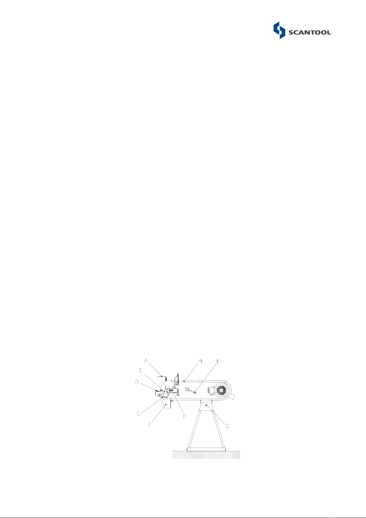
Eye shields, suction hose and perhaps dust bag must be mounted before use. The
clamps for mounting the suction hose are placed in the dust bag. The eye shields
(A) must be mounted into the eye shield fitting (see fig.: 1.1).
The tool rest (B) must be mounted at a distance of minimum 2 mm from the belt,
and the handle (C) must be fastened. Turn the contact wheel by your hand and
adjust the belt by means of the handle (D) until it runs just on the contact wheel
(E). It must be controlled that the spark box (F) is properly fastened. The wanted
working height is adjusted by bolt/locknut (G).
Fig.: 1.1

5
2. Directions
2.1 Operation
After adjustment and connection the belt grinding machine is ready for use. The
grinding can take place by the contact wheel (E) or on the surface grinding table
by opening the cover (H). The lifetime of a new belt is prolonged if the grinding
starts with a light pressure.
2.2 Safety rules for stationary power tools.
Follow them to achieve best results and full benefit from your new machine.
The good craftsman respects
the tools with which he works.
He knows they represent years
of constantly improved design.
He also knows that they are
dangerous if misused.
This is the theme of a new safe-
use program for stationary
power tools. The safety rules
are based on approved
practices in industrial and home
shops
1. Know your
power tool. Read
the owner’s
manual carefully.
Learn its
applications and
limitations, as well
as the specific
potential hazards
peculiar to this
tool.
2. Keep guard in place
and in working order.
3. Ground all tools. If tool is equipped with three-
prong plug, it should be plugged into a three-hole
electrical receptacle. If an adapter is used to
accommodate a two-
prong receptacle, the
adapter wire must be
attached to a known
ground. Never
remove the third
prong.
4. Remove adjusting
keys and wrenches.
Form habit of checking to
see that keys and
adjusting wrenches is
removed before turning it
on.
5. Cluttered areas and benches invite accidents.
6. Avoid dangerous
environment. Don’t use
power tools in damp or wet
locations or expose them to
rain. Keep your work area
well lighted.
6. Keep children away.
All visitors should be
kept in a safe distance
from work area.

6
8. Make workshop kid
proof with padlocks,
master switches, or
by removing starter
keys.
9. Don’t force tool. It will do the job better and be
safer at the rate for
which it was designed.
.
10. Use right tool.
Don’t force tool or
attachment to do
a job it was not
designed for.
11. Wear proper apparel. Wear no loose clothing,
gloves, neckties, rings,
bracelets, or other
jewellery which may get
caught in moving parts.
Non-slip footwear is
recommended. Wear
protective hair covering
to contain long hair.
12. Always use safety
glasses. Also use face or
dust mask if cutting
operation is dusty.
Everyday eyeglasses only
have impact resistant
lenses. They are NOT
safety glasses.
13. Secure works. Use
clamps or vise to hold
works, when practical. It’s
safer than using your
hands and it frees both
hands to operate tool.
14. Don’t
overreach.
Keep proper
footing and
balance at
all times.
15. Maintain tools with care. Keep tools sharp and
clean for best and safest
performance. Follow
instructions for lubricating
and changing accessories.
16. Disconnect tools before
servicing and when changing
accessories such as grinding
wheels, polishing mops,
grinding belts, blades, bits,
cutters, etc.
17. Reduce the risk of unintentional starting. Make
sure switch is in off
position before plugging
in.
18. Use recommended accessories. Consult owner’s
manual for recommended accessories. Use of
improper accessories may cause risk of injury to
persons.

7
2.3 Maintenance
Empty the spark box with regular intervals and control if the suction canals need a
cleaning. The dust bag has to be emptied after use. The contact wheel should be
replaced when the edges have been worn round or the tyre has been damaged.
The graphite pad on the surface grinding table is changed as required.
Fig.: 2.1
When changing the belt it is released by turning the handle (I) in anti-clock-wise
direction (see fig.: 2.1), the cover (J) is opened and the worn-down belt (K) is
removed by driving the belt against the direction of rotation, and the belt is
removed from the machine by the drive wheel. The new belt is fitted. It must be
checked that the direction of the arrows on the back side of the belt correspond to
the direction of rotation. The handle (I) is turned clockwise until grinding belt is
tightened. Check for alignment by turning the grinding belt by hand and adjust with
handle (D)
Fig.: 2.2
To change the contact wheel, remove the grinding belt, tool rest and spark
arrester. Use a 6 mm mandel to hammer out the pin (L). Now the contact wheel
with axle and bearings can be taken out. One of the lock rings (M) and the axle (N)
can be taken out. The new contact wheel (O) is fitted in, in reverse order.

8
3. Spare Parts List
3.1 Drawing of Belt Grinding Machine without Exhaust system.
Fig.: 3.1 Split drawing of belt grinder with no exhaust

9
3.2 Spare Parts List for Belt Grinding Machine without Exhaust System
When ordering spare parts: Please state machine type and serial number together
with item number and description of the part according to this list.
Part Number
Item No.
Description
50-2000
75-2000
100-2000
150-2000
1
Belt release handle
0102267
0102267
0102267
0102267
2
Belt guard
1055931
0239202
0239302
0239502
4
Grinding stop/Cover Blue
1055636
0880002
4532342
4532344
5
Eye shield
0233605
0233605
0233705
0233705
6
Split pin ø6x50 mm
0233050
0233050
0233050
0233050
7
Tool rest
1055634
0233207
0233307
0233507
8
Handle for tool rest
0233808
0233808
0233808
0233808
9
Bolt M10x25
0300134
0300134
0300134
0300134
10
Support for tool rest
0104373
0104373
0104373
0104373
15
Handle M6x25
0233025
0233025
0233025
0233025
18
Fan cover for motor
-
-
-
-
20
Screw M8x12
0300144
0300144
0300144
0300144
21
Graphite pad
0233022
0233221
0233321
0233521
22
Spring 5,5x43x125x11 mm
0102265
0102265
0102265
0102265
23
Fork for contact wheel
1055629
0110223
0110323
0110523
24
Spark box
1055638
0101224
0101324
0101524
25
Star handle Ø32 M6x16
0233806
0233806
0233806
0233806
26
Screw M8x20
0233020
0233020
0233020
0233020
27
Bolt M12x100
4567832
4567832
4567832
4567832
29
Drive wheel
-
-
-
-
32
Base without exhaust system
0239832
0239832
0239832
0239832
35
Side plate
6549081
6549081
6549081
6549081
36
Grinding belt
-
-
-
-
37
Screw M6x45 CH
0950614
0950614
0950614
0950614
39
Fan wheel for motor
-
-
-
-
42
Contact wheel with bearings
1532150
1535005
1535004
1535007
44
Ball handle M6xØ25
0331662
0331662
0331662
0331662
47
Lock nut M8
0928644
0928644
0928644
0928644
48
Switch comp.
-
-
-
-
49
Brake module (optional)
0188845
0188845
0188845
0188845
50
Thermo relay
-
-
-
-
51
Emergency stop comp.
0188892
0188892
0188892
0188892
52
Relay w/0-volt release coil
-
-
-
-
53
Start/stop protection cover
0188893
0188893
0188893
0188893
55
Split pin Ø4x50 mm
0102266
0102266
0102266
0102266
56
Disc 10x45x4
0860327
0860327
0860327
0860327
57
Disc 10mm
0101491
0101491
0101491
0101491
58
Disc 10mm
2323212
2323212
2323212
2323212
59
Disc 8mm
5437850
5437850
5437850
5437850
60
Screw M4x8
0100425
0100425
0100425
0100425
61
Lock nut M6
0951406
0951406
0951406
0951406
62
Hinge mounting for eye shields
0921475
0921475
0921475
0921475
64
Disc 8mm
6540981
6540981
6510981
6540981
66
Lock ring Ø20
0311262
0311262
0311262
0311262
67
Shaft
0233051
0233251
0233351
0233551
68
Lock ring Ø7
0915720
0915720
0915720
0915720
69
Rubber strip 657 mm
1055860
1055860
1055860
1055860
70
Screw M6x12
0930612
0930612
0930612
0930612
71
Wave spring 14x0.3x21
0102268
0102268
0102268
0102268
72
Eccentric for 8 mm motor sheet
0752262
0752262
0752262
0752262
73
Disc 8mm
6540981
6540981
6510981
6540981
78
Screw M4x5
0737620
0737620
0737620
0737620
79
Motor
-
-
-
-
80
Parallel key
-
-
-
-
88
Disc 6mm
0737631
0737631
0737631
0737631
89
Screw M6x10
0110089
0110089
0110089
0110089
91
Disc 8mm
0105167
0105167
0105167
0105167
97
Star M6
0233807
0233807
0233807
0233807
98
Rest for surface grinding
1055679
1055680
1055681
1055682

10
When ordering of spare parts please state machine type and serial number
together with item number and the description of the part according to this list.
Part Number
Item No.
Description
75-2250
75-2500
150-2500
1
Belt release handle
0102267
0102267
0102267
2
Belt guard
1055774
1055775
1055778
4
Grinding stop/Cover Blue
0880002
0880002
4532344
5
Eye shield
0233605
0233605
0233705
6
Split pin ø6x50 mm
0233050
0233050
0233050
7
Tool rest
0233207
0233307
0233507
8
Handle for tool rest
0233808
0233808
0233808
9
Bolt M10x25
0300134
0300134
0300134
10
Support for tool rest
0239373
0239373
0239373
15
Handle M6x25
0233025
0233025
0233025
18
Fan cover for motor
-
-
-
20
Screw M8x12
0300144
0300144
0300144
21
Graphite pad
0233921
1055664
0233421
22
Spring 5,5x43x125x11 mm
0102265
0102265
0102265
23
Fork for contact wheel
0110223
0110223
0110523
24
Spark box
0101224
0101324
0101524
25
Star handle Ø32 M6x16
0233806
0233806
0233806
26
Screw M8x20
0233020
0233020
0233020
27
Bolt M12x100
4567832
4567832
4567832
29
Drive wheel
-
-
-
32
Base without exhaust system
0239832
0239832
0239832
35
Side plate
1055772
1055773
1055777
36
Grinding belt
-
-
-
37
Screw M6x45 CH
0950614
0950614
0950614
39
Fan wheel for motor
-
-
-
42
Contact wheel with bearings
1535005
1535005
1535007
44
Ball handle M6xØ25
0331662
0331662
0331662
47
Lock nut M8
0928644
0928644
0928644
48
Switch comp.
-
-
-
49
Brake module (optional)
0188845
0188845
0188845
50
Thermo relay
-
-
-
51
Emergency stop comp.
0188892
0188892
0188892
52
Relay w/0-volt release coil
-
-
-
53
Start/stop protection cover
0188893
0188893
0188893
55
Split pin Ø4x50 mm
0102266
0102266
0102266
56
Disc 10x45x4
0860327
0860327
0860327
57
Disc 10mm
0101491
0101491
0101491
58
Disc 10mm
2323212
2323212
2323212
59
Disc 8mm
5437850
5437850
5437850
60
Screw M4x8
0100425
0100425
0100425
61
Lock nut M6
0951406
0951406
0951406
62
Hinge mounting for eye shields
0921475
0921475
0921475
64
Disc 8mm
6540981
6540981
6540981
66
Lock ring Ø20
0311262
0311262
0311262
67
Shaft
0233251
0233251
0233551
68
Lock ring Ø7
0915720
0915720
0915720
69
Rubber strip
1055807
1055808
1055808
70
Screw M6x12
0930612
0930612
0930612
71
Wave spring 14x0.3x21
0102268
0102268
0102268
72
Eccentric for 8 mm motor sheet
0752262
0752262
0752262
73
Disc 8mm
6540981
6540981
6540981
78
Screw M4x5
0737620
0737620
0737620
79
Motor
-
-
-
80
Parallel key
-
-
-
88
Disc 6mm
0737631
0737631
0737631
89
Screw M6x10
0110089
0110089
0110089
91
Disc 8mm
0105167
0105167
0105167
97
Star M6
0233807
0233807
0233807
98
Rest for surface grinding
1055680
1055680
1055682

11
3.3 Belt Grinding Machine with Exhaust System
Fig.: 3.2 Split drawing of belt grinder with exhaust

12
3.4 Spare parts List for Belt Grinding Machine with Exhaust System
When ordering of spare parts please state machine type and serial number together with item
number and description of the part according to this list.
Part Number
Item No.
Description
50X-2000
75X-2000
100X-2000
150X-2000
1
Belt release handle
0102267
0102267
0102267
0102267
2
Belt guard
1055931
0239202
0239302
0239502
4
Grinding stop/cover blue
1055636
0880002
4532342
4532344
5
Eye shield
0233605
0233605
0233705
0233705
6
Split pin ø6x50 mm
0233050
0233050
0233050
0233050
7
Tool rest
1055634
0233207
0233307
0233507
8
Handle for tool rest
0233808
0233808
0233808
0233808
9
Screw M10x25
0300134
0300134
0300134
0300134
10
Support for tool rest
0104373
0104373
0104373
0104373
11
Suction hose ø63
7891011
7891011
7891011
7991011
13
Fan cover for exhaust motor
2075180
2075180
2075180
2075180
14
Dust bag
0811793
0811793
0811793
0811793
15
Handle M6x25
0233025
0233025
0233025
0233025
16
Lock Nut M12
0105166
0105166
0105166
0105166
17
Cable
0963078
0963078
0963078
0963078
18
Fan cover for motor
-
-
-
-
20
Screw M8x12
0300144
0300144
0300144
0300144
21
Graphite pad
0233221
0233221
0233321
0233521
22
Spring 5,5x43x125x11 mm
0102265
0102265
0102265
0102265
23
Fork for contact wheel
1055629
0101224
0101324
0101524
25
Star handle Ø32 M6x16
0233806
0233806
0233806
0233806
26
Screw M8x20
0233020
0233020
0233020
0233020
27
Screw M12x100
4567832
4567832
4567832
4567832
29
Drive wheel
-
-
-
-
33
Hose strap 58-75 mm
0233058
0233058
0233058
0233058
35
Side plate
6549081
6549081
6549081
6549081
36
Grinding belt
-
-
-
-
37
Screw M6x45 CH
0950614
0950614
0950614
0950614
38
Dust extractor
0233852
0233852
0233852
0233852
39
Fan wheel for motor
-
-
-
-
41
Fan wheel for exhaust motor
2031015
2031015
2031015
2031015
42
Contact wheel with ball bearings
1532150
1535005
1535004
1535007
44
Ball handle M6xØ25
0331662
0331662
0331662
0331662
47
Lock nut M8
0928644
0928644
0928644
0928644
48
Switch box
-
-
-
-
49
Brake module –optional
0188845
0188845
0188845
0188845
50
Thermo relay
-
-
-
-
51
Emergency stop comp.
0188892
0188892
0188892
0188892
52
Relay w/0-volt release coil
-
-
-
-
53
Start/stop protection
0188893
0188893
0188893
0188893
55
Split pin Ø4x50 mm
3454351
3454351
3454351
3454351
56
Disc 10x45x4
0860327
0860327
0860327
0860327
57
Disc 10mm
0101491
0101491
0101491
0101491
58
Disc 10mm
2323212
2323212
2323212
2323212
59
Disc 8 mm
5437850
5437850
5437850
5437850
60
Screw M4x8
0100425
0100425
0100425
0100425
61
Lock Nut M6
0951406
0951406
0951406
0951406
62
Hinge mounting for eye shields
0921475
0921475
0921475
0921475
64
Disc 8mm
6540981
6540981
6540981
6540981
66
Lock ring Ø20
0311262
0311262
0311262
0311262
67
Shaft
0233051
0233251
0233351
0233551
68
Lock ring Ø7
0915720
0915720
0915720
0915720
69
Rubber strip
1055860
1055860
1055860
1055860
70
Screw M6x12
0930612
0930612
0930612
0930612
71
Wave spring 14x0.3x21
0102268
0102268
0102268
0102268
72
Eccentric for 8 mm motor sheet
1055462
0752262
0752262
0752262
73
Disc 8mm
6540981
6540981
6540981
6540981
77
Parallel key 36x6x6
0110077
0110077
0110077
0110077
78
Screw M4x5
0737620
0737620
0737620
0737620
79
Motor
-
-
-
-
80
Parallel key
-
-
-
-
81
Screw M4x12
0737610
0737610
0737610
0737610
82
Cover for terminal box
0110082
0110082
0110082
0110082
83
Exhaust motor 0.5HP
2030040
2030040
2030040
2030040
84
Fan wheel large 250 mm
0995704
0995704
0995704
0995704
85
Disc 5mm
0233030
0233030
0233030
0233030
86
Screw M5x30
0331786
0331786
0331786
0331786
88
Disc 6mm
0737631
0737631
0737631
0737631
89
Screw M6x10
0110089
0110089
0110089
0110089
91
Disc 12mm
0105167
0105167
0105167
0105167
92
Disc 8mm
5437850
5437850
5437850
5437850
93
Suction box for exhaust system
2578909
2578909
2578909
2578909
94
Suction hose ø102 mm
6721303
6721303
6721303
6721303
95
Hose strap 90-110 mm
0233110
0233110
0233110
0233110

13
96
Spark box with exhaust system
1055643
0102224
0102324
0102524
97
Star M6
0233807
0233807
0233807
0233807
98
Rest for surface grinding
1055679
1055680
1055681
1055682
When ordering of spare parts please state machine type and serial number
together with item number and description of the part according to this list.
Part Number
Item No.
Description
75X-2250
75X-2500
150X-2500
1
Belt release handle
0102267
0102267
0102267
2
Belt guard
1055774
1055775
1055778
4
Grinding stop/cover blue
0880002
0880002
0233521
5
Eye shield
0233605
0233605
0233605
6
Split pin ø6x50 mm
0233050
0233050
0233050
7
Tool rest
0233207
0233207
0233207
8
Handle for tool rest
0233808
0233808
0233808
9
Screw M10x25
0300134
0300134
0300134
10
Support for tool rest
0104373
0104373
0104373
11
Suction hose ø63
7891011
7891011
7891011
13
Fan cover for exhaust motor
2075180
2075180
2075180
14
Dust bag
0811793
0811793
0811793
15
Handle M6x25
0233025
0233025
0233025
16
Lock Nut M12
0105166
0105166
0105166
17
Cable
0963078
0963078
0963078
18
Fan cover for motor
-
-
-
20
Screw M8x12
0300144
0300144
0300144
21
Graphite pad
0233921
0233222
0233421
22
Spring 5,5x43x125x11 mm
0102265
0102265
0102265
23
Fork for contact wheel
0101224
0101224
0101224
25
Star handle Ø32 M6x16
0233806
0233806
0233806
26
Screw M8x20
0233020
0233020
0233020
27
Screw M12x100
4567832
4567832
4567832
29
Drive wheel
-
-
-
33
Hose strap 58-75 mm
0233058
0233058
0233058
35
Side plate
1055772
1055773
1055777
36
Grinding belt
-
-
-
37
Screw M6x45 CH
0950614
0950614
0950614
38
Dust extractor
0233852
0233852
0233852
39
Fan wheel for motor
-
-
-
41
Fan wheel for exhaust motor
2031015
2031015
2031015
42
Contact wheel with ball bearings
1535005
1535005
1535005
44
Ball handle M6xØ25
0331662
0331662
0331662
47
Lock nut M8
0928644
0928644
0928644
48
Switch box
-
-
-
49
Brake module –optional
0188845
0188845
0188845
50
Thermo relay
-
-
-
51
Emergency stop comp.
0188892
0188892
0188892
52
Relay w/0-volt release coil
-
-
-
53
Start/stop protection
0188893
0188893
0188893
55
Split pin Ø4x50 mm
3454351
3454351
3454351
56
Disc 10x45x4
0860327
0860327
0860327
57
Disc 10mm
0101491
0101491
0101491
58
Disc 10mm
2323212
2323212
2323212
59
Disc 8 mm
5437850
5437850
5437850
60
Screw M4x8
0100425
0100425
0100425
61
Lock nut M6
0951406
0951406
0951406
62
Hinge mounting for eye shields
0921475
0921475
0921475
64
Disc 8mm
6540981
6540981
6540981
66
Lock ring Ø20
0311262
0311262
0311262
67
Shaft
0233251
0233251
0233251
68
Lock ring Ø7
0915720
0915720
0915720
69
Rubber strip
1055807
1055808
1055808
70
Screw M6x12
0930612
0930612
0930612
71
Wave spring 14x0.3x21
0102268
0102268
0102268
72
Eccentric for 8 mm motor sheet
0752262
0752262
0752262
73
Disc 8mm
6540981
6540981
6540981
77
Parallel key 36x6x6
0110077
0110077
0110077
78
Screw M4x5
0737620
0737620
0737620
79
Motor
-
-
-
80
Parallel key
-
-
-
81
Screw M4x12
0737610
0737610
0737610
82
Cover for terminal box
0110082
0110082
0110082
83
Exhaust motor 0.5HP
2030040
2030040
2030040
84
Fan wheel large 250 mm
0995704
0995704
0995704
85
Disc 5mm
0233030
0233030
0233030
86
Screw M5x30
0331786
0331786
0331786
88
Disc 6mm
0737631
0737631
0737631
89
Screw M6x10
0110089
0110089
0110089
91
Disc 12mm
0105167
0105167
0105167

14
92
Disc 8mm
5437850
5437850
5437850
93
Suction box for exhaust system
2578909
2578909
2578909
94
Suction hose ø102 mm
6721303
6721303
6721303
95
Hose strap 90-110 mm
0233110
0233110
0233110
96
Spark box with exhaust system
0102224
0102224
0102524
97
Star M6
0233807
0233807
0233807
98
Rest for surface grinding
1055680
1055680
1055680
4. Technical Data
4.1 Technical Specifications
Model
50
50X
75
75X
100
100X
150
150X
Grinding belt
50x2000
50x2000
75x2000
75x2250
75x2500
75x2000
75x2250
75x2500
100x2000
100x2000
150x2000
150x2500
150x2000
150x2500
Motor 3x380-440
V 50 Hz
3,6 HK
3,6 HK
4,1 HK
4,8 HK
4,1 HK
4,8 HK
4,8 HK
4,8 HK
4,8 HK*
4,8 HK*
Class
IEC 34-1
IEC 34-1
IEC 34-1
IEC 34-1
IEC 34-1
IEC 34-1
IEC 34-1
IEC 34-1
IP Class
54
54
54
54
54
54
54
54
r/min.
2860
2860
2860
2860
2860
2860
2860
2860
Ampere
10,6/6,0
10,6/6,0
10.6/6.1
10.6/6.1
10.6/6.8
10.6/6,8
10.6/6.8
10.6/6.8
Cos
0,91
091
0,91
0,91
0,91
0,91
0,91
0,91
Belt speed
30 m/s
30 m/s
30 m/s
30 m/s
30 m/s
30 m/s
30 m/s
30 m/s
Contact wheel
Ø200x50
Ø200x50
Ø200x75
Ø200x75
Ø200x100
Ø200x100
Ø200x150
Ø200x150
Fan motor
-
0,5 HK
-
0,5 HK
-
0,5 HK
-
0,5 HK
Weight 2000
50 kg
70 kg
60 kg
80 kg
70 kg
90 kg
80 kg
100 kg
Weight 2250
-
-
70 kg
90 kg
-
-
-
-
Weight 2500
-
-
90 kg
100 kg
-
-
110 kg
130 kg
*5,5 HP motor available.
The noise level for SCANTOOL belt grinding machine has been measured to 80 dB (A) according
to the measuring instruction in the note 561 from the Work Inspection Department on device of
technical aids.
4.2 Dimensions
Fig.: 4.2
Model
A
B
C
D
E
F
G
H
I
J
K
50-2000
995
660
945
830-970
605
635
365
395
392
306
86

15
75-2000
995
660
945
830-970
605
635
365
395
413
306
107
75-2250
1050
775
945
830-970
605
635
365
395
413
306
107
75-2500
1180
900
945
830-970
605
635
365
395
413
306
107
100-2000
995
660
945
830-970
605
635
365
395
439
306
133
150-2000
995
660
945
830-970
605
635
365
395
491
306
185
150-2500
1180
900
945
830-970
605
635
365
395
491
306
185
4.3 Circuit diagrams
Belt grinding machines can be connected to 3 x 400/440 V, 50/60 cycles and to 3
x 230 V 50/60 cycles. There are three kinds of circuit diagrams:
1. One velocity grinder without brakes see 4.3.1 and 4.3.2
2. One velocity grinder with brakes see 4.3.3 and 4.3.4
3. Two velocity grinder with no brakes see 4.3.5 and 4.3.6
When the motor is for 3x480 V utilize same diagrams as for 3x400/440.
Fig. 4.3.1.: Diagram of belt grinder with no exhaust motor.

16
Fig. 4.3.2.: Diagram of belt grinder with exhaust motor.
Fig.: 4.3.3 Diagram of belt grinder with brake and no exhaust motor.

17
Fig.: 4.3.4 Diagram of belt grinder with brake and exhaust motor.
Fig.: 4.3.5 Diagram of belt grinder with two velocities and no exhaust motor.

18
Fig.: 4.3.6 Diagram of belt grinder with two velocities and no exhaust motor.

19
4.4 Pressure diagram
The fan is especially developed for belt grinders. It provides a pressure of up to 1300 Pa
and an air flow from 0 to 650 m³/hour. It is manufactured in 1,5 mm sheet steel and is
welded. Available in 3x400V and 50/60Hz, 2800 revolutions per min. The ventilator is
encapsulated in class IP54.
This manual suits for next models
3
Table of contents
Other Scantool Industrial Equipment manuals
Popular Industrial Equipment manuals by other brands

Danfoss
Danfoss IPS 8 Startup guide

Emerson
Emerson Bettis RTS Installation, operation and maintenance manual

Siemens
Siemens SINUMERIK ONE NCU 1760 Equipment manual

Avlite
Avlite AV-OL-75 Installation & service manual

Planeta
Planeta SA 250 Installation and operation manual

Axel Semrau
Axel Semrau ODOR easy manual