Scantool 85VB User manual

Industrivej 3-9
DK-9460 Brovst
Tlf.: +45 98 23 60 88
Fax: +45 98 23 61 44
Manual
SCANTOOL 85VB
Metal cutting bandsaw

2
EC Declaration of Conformity
hereby declares that
SCANTOOL 85VB are manufactured in accordance with the provisions of the COUNCIL
DIRECTIVE of 17. May 2006(2006/46/EC)
Also on accordance with:
·The council directive of 19 February 1973 (73/23/EEC) –The Low Voltage
Directive –with later amendments (order no. 797 of 30 August 1994)
·The council directive of 3 May 1989 (73/336/EEC) –The EMC Directive –with later
amendments (order no. 796 of 5 December 1991 with subsequent amendments)
SCANTOOL A/S
Industrivej 3-9
9460 Brovst
Denmark
www.scantool-group.com
Tlf: +45 98 23 60 88
Fax.: +45 98 23 61 44

3
Table of Contents
1OPERATION 5
1.1 SAFETY RULES FOR STATIONARY POWER TOOLS. 5
1.2 WARING 6
2INTRODUCTION TO USE 9
2.1 SYMBOLS PLACED IN CORRESPONDANCE WITH USAGE POINTS 9
2.2 RECOMMENED AND NOT RECOMMENDED USAGE 9
2.3 STANDARD SAFEY PROCEDURS 10
2.4 SAFETY PROCEDURS FOR FURTHER RISK 10
2.5 NOISE CONDITIONS 10
2.6 INFORMATION ABOUT THE ELECTROMAGNE-TIC COMPATIBLLITY 10
2.7 DESCRIPTION OF THE MACHINE (FIG.1) 11
3INSTALLAZONE 11
3.1 REMOVING THE PACKING 11
3.2 HANDLING (FIG.2) 11
3.3 TRANSPORT (FIG.2) 11
3.4 POSITION/WORK STATION (FIG.3) 12
3.5 ELECTRICAL CONNECTIONS 12
4ADJUSTING (FIG. 4-5-6-7-8) 12
4.1 TENSION OF TME BLADE (FIG.4) 12
4.2 BAR STOP (FIG.5) 12
4.3 CUTTING ANGLE (FIG.6) 13
4.4 CUTTING SPEED (FIG.7) 13
4.5 SLIDING BLADE GUIDE (FIG.8) 13
4.6 BEARINGS BLADE GUIDE (FIG.9) 13
5USE 14
5.1 RUNING IN THE BLADE 14
5.2 WORKING(FLG.7) 14
5.3REPLACING THE BLADE (FIG.9) 15
5.4 CUTTING CAPACITY 16
5.5 CORRECT POSITIONING OF THE PIECE IN THE CLAMP 17
5.6 CUTTING TABLE 17
6ACCESSORIES 18
6.1 CHOISE OF BLADE 18
7MAINTENANCE 18

4
7.1 REGULAR MAINTENANCE 18
7.2 ASSISTENCE 18
7.3 DISFOSAL OF THEMACHINE 18
8TROUBLESHOOTING 19
9DIAGRAM 20
10 PARTS LIST FOR SCANTOOL 85 VB 24

5
1 Operation
1.1Safety rules for stationary power tools.
Follow them to achieve best results and full benefit from your new machine
The very good craftsman respects the tools with
which he works. He knows they represent years
of constantly improved design. He also knows
that they are dangerous if misused.
This is the theme of a new safe-use program for
stationary power tools. The safety rules are
based on approved practices in industrial and
home shops.
1. Know your power tool. Read
the owner’s manual carefully.
Learn its applications and
limitations, as well as the
specific potential hazards
peculiar to this tool.
2. Keep guard in place
and in working order.
3. Ground all tools. If tool is equipped
with three-prong plug, it should be
plugged into a three-hole electrical
receptacle. If an adapter is used to
accomodate a two-prong receptacle,
the adapter wire must be attached to
a known ground. Never remove the
third prong.
4. Remove adjusting keys
and wrenches. Form habit of
checking to see that keys
and adjusting wrenches is
removed before turning it on.
5. Keep work area clean.
Cluttered areas and benches
invite accidents.
6. Avoid dangerous
environment. Don’t use
power tools in damp or wet
locations or expose them to
rain. Keep your work area
well lighted.
7. Keep children away. All
visitors should be kept in a
safe distance from work
area.
8. Make workshop kidproof with
padlocks, master switches, or by
removing starter keys.

6
17. Reduce the risk of
unintentional starting. Make sure
switch is in off position before
plugging in.
9. Don’t force tool. It will do the job
better and be safer at the rate for
which it was designed.
10. Use right tool. Don’t force
tool or attachment to do a job it
was not designed for.
11. Wear proper apparel. Wear no
loose clothing, gloves, neckties,
rings, bracelets, or other jewelry
which may get caught in moving
parts. Non-slip footwear is
recommended. Wear protective
hair covering to contain long hair.
12. Always use safety
glasses. Also use face or
dust mask if cutting
operation is dusty. Everyday
eyeglasses only have impact
resistant lenses. They are
NOT safety glasses.
13. Secure works. Use clamps
or vise to hold works, when
pratical. It’s safer than using
your hands and it frees both
hands to operate tool.
14. Don’t overreach. Keep proper
footing and balance at all times.
16. Disconnect tools before servicing and when
changing accessories such as grinding wheels,
polishing mops, grinding belts, blades, bits,
cutters, etc.
18. Use recommended accessories.
Consult owner’s manual for
recommended accessories. Use of
improper accessories may cause risk
of injury to persons.
15. Maintain tools with
care. Keep tools sharp and
clean for best and safest
performance. Follow
instructions for lubricating
and changing accessories.

7
1.2 WARNING!
Some dust created by power sanding, sawing, grinding, drilling, and other
construction activities contains chemicals known to the State of California to
cause cancer, birth defects or other reprodrctive harm. Some examples of
these chemical are:
· Lead from lead-based paints.
· Crystalline silica from bricks, cement and other masonry products.
· Arsenic and chromium from chemically-treated lumber.
Your risk from these exposures varies, depending on how often you do this
type of work. To reduce your exposure to these chemicals: Work in a well
ventilated area, and word with approved safety equipment, such as those
dust masks that are specially designed to filter out microscopic particles.

8

9
2 INTRODUCTION TO USE
Before starting work with your sawing machine, carefully read this instructions manual so
that you are familiar with the machine and its uses and where it should not be used. Keep
this manual in a safe place.
It is an integral part of the machine and should be used for reference in operating the
machine correctly and in the
proper safety conditions.
Use the machine only and exclusively for the uses specified below, as recommended in
this manual. The machine should not in any way be tampered with, or forced, or used for
unsuitable purposes.
2.1 SYMBOLS PLACED IN CORRESPONDANCE WITH USAGE POINTS
Never underestimate the warnings " ATTENTION CAUTION " given in this manual.
In order to draw the user's attention and to preserve safety, hazard-ous operation are
preceded by symbols and notes that point out the danger and explain how to behave to
avoid any risk.
These symbols and notes are divided in three categories, identified by the following
words:
Attention: dangerous-behaviours that could cause serious injuries.
CAUTION: behaviours that could cause slight injuries or damages to things.
NOTE: the notes preceded by this symbols are technical and are aimed at making
operations easier.
2.2 RECOMMENED AND NOT RECOMMENDED USAGE
This belt sawing machine was designed and constructed according to the most advanced
technologies and may be used for all cutting requirements for metals commonly used in
industry and artisanship.
It can cut:
.COMMON STEELS (FE 37...)
.SPECLAL STEELS (C 40, 18NiCrMo5...)
.ALUMINIUM AND ITS ALLOYS
.BRASS
.BRONZE
.STEEL TUBING (FE 35, FE 52,..)
.PROFILED SECTIONS IN SHEET METAL AND ALUMINIUM
It is not suitable for cutting:
-WOOD AND SIMILAR MATERALS
-BONE AND SIMILAR MATERIALS
The band saw has been developed and manufactured to cut in dry condition; the use of
any cooler by lubricating oil makes the machine unusable.
Consult the relative sections for cutting capacities, the speeds to use and the type of tools
for use according to the material to be cut and its section.(See list of contents).

10
2.3STANDARD SAFEY PROCEDURS
-Do not use the machine in very damp places or in the presence of inflammable liquids or
gases.
-Do not use it in the open air when general weather and environ-mental conditions are
unfavourable (eg. Explosive atmospheres, during a storm or rain).
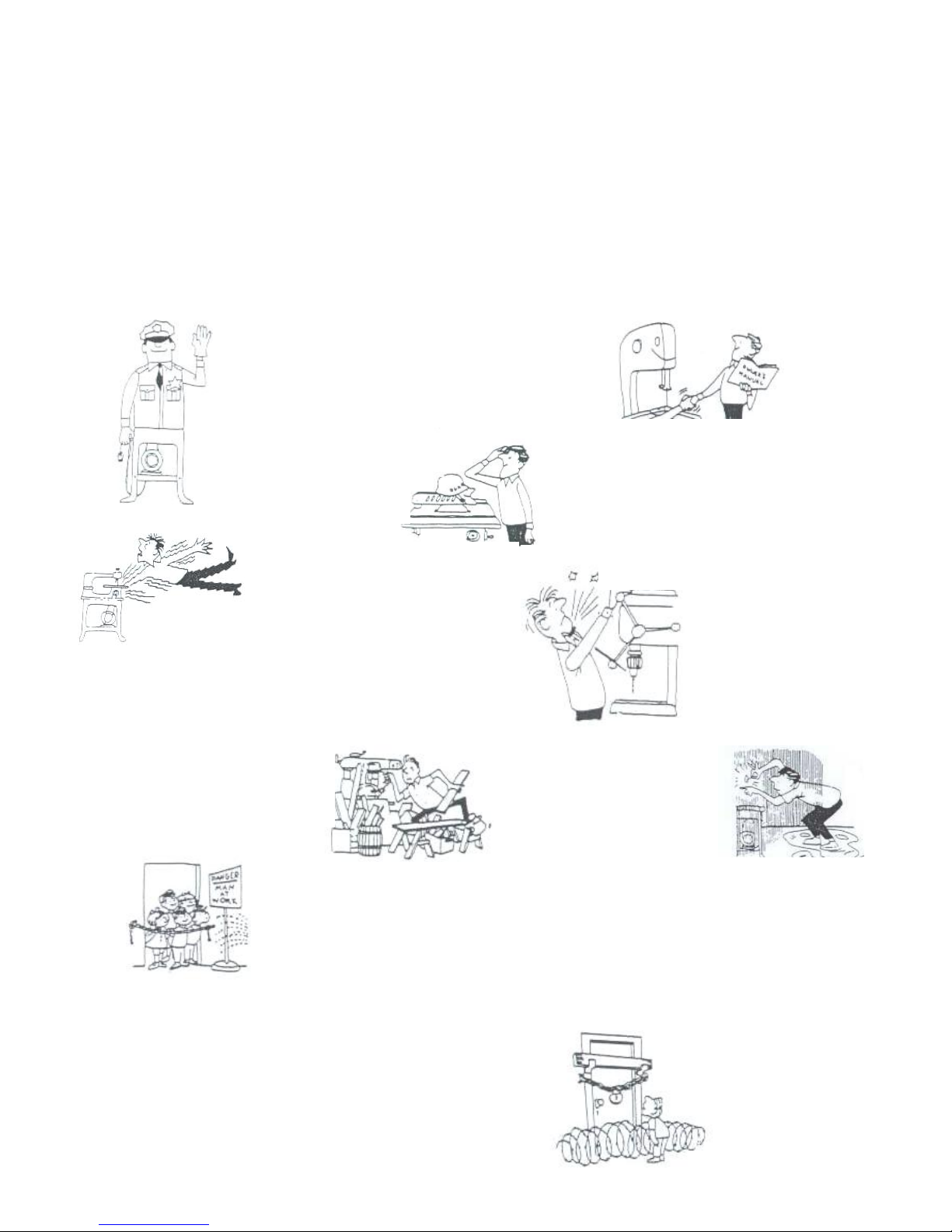
-Wear suitable clothes, without wide sleeves or articles such as scarves. chains and
bracelets which could get caught in the moving parts.
-Always use personal protection devices: protective goggles as recommended by safety
standards, gloves of the right size, head-phones or earplugs, and hairnets if necessary
-Use the tools recommended in this manual if you want to achieve the best performance
from your sawing machine.
-Any power cable extensions must be type approved and comply with safety standards.
-avoid using the machine if your psycho-physical condition are pre-carious or upset.
2.4SAFETY PROCEDURS FOR FURTHER RISK
-Always keep processing residues away from the cutting area.
-Always use the clamp. The parts to be cut must always be held firmly in the clamp.
-Always keep hands away from the working areas while the machine is moving: before
loading or unlading the part, release the run button on the hand grip.
-Do not force the machine unnecessarily : excessive cutting pressure could cause rapid
wear to the blade and negatively influence the performance of the
machine in terms of finishes and cutting precision.
2.5 NOISE CONDITIONS
In normal conditions of use as described in this manual, this belt sawing machine
determines an equivalent level of acoustic pressure:
Leq= 82d8(A) when operating unloaded;
Leq= 84.3 dB(A) during processing (eg. cutting of a steel tube D.80mm thickness 5mm),
at cutting speed of 80m/min., with a weighted operating cycle of 1 minute.
Measurement were obtainesl in complfance with UNI 7712, ISO 3740,IS0 3746 and CEE
89/392 regulation.
NOTE : Personal hearing protection should be used, such as headphones or earplugs.
2.6 INFORMATION ABOUT THE ELECTROMAGNE-TIC COMPATIBlLITY
The European regulations on safety and , in particular, the EEC Directive 89/336
contemplate that all the equipment be equipped with shielding devices against radio
interferences both from and towards the outside
This machine is equipped with filters both on the motor and on the power supply through
which the machine is safe and in compliance with above regulations.
Tests were carried out according to EN 55011 , EN 55014, EN50082-1, IEC 1000-4-2,
IEC 1000-4-4 regulations.

11
2.7 DESCRIPTION OF THE MACHINE (Fig.1)
The belt sawing machine consists of two basic parts: the machine body (5) complete with
motor and drive (7) which is integrated Into lower part. consisting of the clamp (11) and
the base (13), by means of the swivel support (9). Here is a list of the main parts with the
number indicating it in the drawing.
Legend F-ig. 1
1 -Command grip
2 -Blade tension handwheel
4 - Sliding blade guide
5 -Machine body 6 -Blade
7 -Motor
8 -Control box
9 -Bar stop
10 -Clamp (vice)
11 -Morsa
12 -Clamp drive
13 -Base
WEIGHT= 16KG
SIZE = cm 85 * 36 * H65 in maximum overall dimensions.
PACKAGING SIZE =cm 72' 34 ` H52
3 INSTALLAZONE
3.1 REMOVING THE PACKING
Remove the wooden frame which protects the machine during transit
Try not to damage the frame as you may have to move the machine long distances or
store it for long periods.
3.2HANDLING (FIg.2)
As the machine is not heavy (Kg 16), it can be lifted and moved by a single person by
gripping it
from the machine body (5). duly clamped (see pint 2.3)
3.3TRANSPORT (Fig.2)
It is necessary to low the saw body till the lower position and fix it to the base : it is
sufficient to insert the pin U in the hole in the body , then lift the machine, gripping it as
showed in Fig.2.
For transport the machine, it is better to place it in the box it was when purchased.
Ensure it is placed in the correct position indicated by the arrows on the packaging.
Pay careful attention to the ideogram printed on the box as they provide all necessary
information for palletization and stacking of boxes.
Tying the load down with ropes or safety belts is raccomended during transportation to
prevent the load from sliding or falling.

12
3.4 POSITION/WORK STATION (Fig.3)
Place the machine on a sufficiently flat workbench so that the machine has the better
possible stability.
In respect of ergonomic criteria during cutting operations, the workbench must be
positioned at such a height that the clamp level is between 90 and 95 cm from the ground
(see fig.3)
Make sure that the machine is placed in a working area with suitable environmental
conditions and lighting. The general conditions of the working environment are of
fundamental importance for accident prevention.
3.5 ELECTRICAL CONNECTIONS
Check that the mains to which the machine is connected is earthed in accordance with
current safety regulations and that the power point is in good condition.
Remember that there should be a magnetothermic protective device itted upstream of the
mains to protect all the conductors from short circuits and overioads.
This protective device should be selected according to the electrical features of the
machine listed below:
Nominal voltage................................. 230Volti
Nominal frequency ............................ 50/60Herlz
Max programmed absorbed value.... .2.5Ampere
Nominal input power.......................... 850Watt
Power factor ................................. .... 0.92
Nominal speed ............................ ..... 10.000-23.OOOrpm
Insulation ....................... ......... ...... Classe B
Type of service ......... . ................. ... intermittent S4-60 %
In case of power failure in mains, while you wait for power to be restored there is no
danger hazard may arise: in face, the electronic governor O or main switch D is also
equipped with a reset function which prevents the machine from restarting automatically.
The motor of your sawing machine (electronic version)is equipped with a protective heat
circuit breaker which interrupts the power supply when the temperature of the coils rlses
too high.
When the power supply is interrupted, wait for normal reset.
4 ADJUSTING (Fig. 4-5-6-7-8)
4.1 TENSION OF TME BLADE (Fig.4)
Turn the handwheel B in a clockwise direction until it locks.
If the tension is too high, the blade tends to escape from the guide. In this case, slacken
the blade tension by turning of one/two turns the handwheel B in a anti clockwise
direction.
4.2 BAR STOP (Fig.5)
Use the bar stop supplied if you have to do several cuts on pieces of the same length.
In this way you do not have to repeat the same measurement each time.
Screw rod E into the hole of the base and fasten it with nuts F. Slacken the handwheel G
and place the stop L at the correct distance from the blade. Tighten handwheel G again.

13
4.3 Cutting angle (Fig.6)
The band saw can cut at an angle varying from 0 to 45 degrees : it is sufficient to slacken
the handle I and turn the swiwel support J towards the respective limit stops H and K.
For all intermediate angles, turn the swiwel support J until
the mark M on the support matches the corresponding position on the plate.
Then Iock the rotating support J again.
4.4 CUTTING SPEED (Fig.7)
Two speed version
Depending on the type of material and its section (see CUTTINGTABLE) you can choose
two different cutting speed 60 or 80 m/min. by means of the switch N.
Electronic version
Your sawing machine is equipped with CESC (Constant Electronic Speed Control), which
allows gradual and continuous variation of the cutting speed , adapting it to the type and
dimension of the material to be cut (see CUTTING TABLE).
To select the most suitable speed, use the speed control knob O to increase or decrease
the speed as you require.
Example:
Stainless Steel: 30mlmin. position 1
Common Steel: 40-60m/min. position 2-3-4
AlIum. Alloy: 80m/min. position 6
Pipes/sections: 70-80m/min position 5-6
4.5SLIDING BLADE GUIDE (Fig.8)
The sliding blade guide P with integrated protection fitted
on your sawing machine is used to perform the cut while guiding the necessary part of the
blade and fully protecting the part not used in the cutting process.
Slacken the knobs Q and slide the blade guide P so as to move it closer to or further from
the part to be cut, a5 shown in the figure.
If this adjustment is not done, the part of the blade not used in the cutting process will be
exposed and this will create an extra risk of contact, besides altering the quality of the cut.
4.6 BEARINGS BLADE GUIDE (Fig.9)
The blade-auide on the outside of the sawing machine are eccentric and adjustable so as
to simplify blade replacement and to keep it guided as its best.
They must always touch the blade slightly, so that they rotate when the blade passes, but
must not be completely locked.
In order to approach or remove the eccentric blade-guide, gently turn the head of the
screws S using a 10 mm.
Wrenches key.

14
5 USE
5.1 RUNING IN THE BLADE
if the correct running in procedure is not performed, the blade's cutting precision may be
irreparably compromised.
To obtain the best performance, the bi-metal blades fitted on your sawing machine must
be run in for a short period. For this reason the first two or three cuts should be done
where possible on a solid piece D.40-50 mm, using a very slight pressure on the blade,
and gradually increasing pressure in subsequent cuts.
To gauge the correct pressure in normal operating conditions defined by this manual (see
cutting table), consider for example that the first cut on solid steel (eq. C40) D.50 mm
should be done in about 4 minutes. After running-in , the same piece may easily be cut in
about 2 minutes. If the running-in process is done correctly, the finish and precision of the
cut will be of better quality and the blade will last longer.
5.2 WORKING(Flg.7)
Two speed version
Push the green button "1"of the main switch D to anable machine operation.
Electronic version
Turn the main switch D to position 1 :in doing the switch comes on and the machine is
ready for operation. Before starting any cutting operation, check that all the protections
are complete and in the correct position.
Once you have completed all the procedures and operations described so far, you may
start the working processes.
To perform the cut, move to the front of the machine and grip the handgrip with your right
hand.
Keep your left hand away from the cutting area and on no account try to reach it when
cutting Is In process. Using the index finger of your right hand, press the run button A
(Fig.4) and gradually lower the machine body until it comes lightly into contact with the
part to be cut. Now begin to apply gradual pressure on the part and compete the cut.
Always release button A between one cutting operation and another, while you are
positioning the part. Do not try to block it or alter its functional
characteristics in any way.
Electronic version
If the machine suddenly stops after numerous consecutive cuts, do not be alarmed. The
heat protector device of the motor has been activated, breaking the power supply when
the temperature of the coils reaches the threshold limit defined by the insulation class, to
prevent damage to the motor.
In this case, release the button A and wait for automatic reset which usually takes place
after a few minutes,
Your sawing machine is equipped with an electronic speed governor which also includes a
motor protection function obtained by means of an amperometric limiter, In this way it can
not absorb an amount of current greater than the set one, expressed by the maximum
value of absorption (see 2.5).
If the limiter trips while the machirl8 Is in operation, slighty decrease the cutting pressure
in addition, this enables to safeguard the blade life and performance and to obtain .aIways
a sharp and clean cut.

15
5.3 replacing the blade (Fig.9)
When you perform the operation, always wear protective glovesto avoid contact with the
teeth of the blade.
-check that the main switch D is at position O;
-slacken the handle Q and slide the blade guide P as far as it will go, following the
direction on the arrow (Fig.8);
-remove the protective casing unscrewing the four screws;
-slacken the blade tension, turning the handwheel B in a anti-clockwise direction;
-using a 10mm. Spanner, slacken the exagonal nuts R on the two blade guides on the
outside of the blade (Fig.9); -with the same spanner gently turn the head of the screws
on the same blade-guide in a anti-clockwise direction so as to move the bearinqs far
enogh away from the blade to enable you to extract it easily from the guides ;
-extract the blade first from the guides and then from the rubber coated pulleys;
-insert the new blade first between the guides and then onto the rubber coated pulleys,
with the teeth facing as showed in picture 9;
-put the blade under tension again as described in point
3.1 and reposition the two outer blade guides in slight contact with the blade, tuming the
head of the screws S
in a clockwise direction;
-lock the two exagonal nuts R again;
-replace the protective casing, being careful to insert the blade between the straps of the
protection T;
-reposition the blade guides Pin the correct position for the next cut.

16
5.4 CUTTING CAPACITY
The table below specifies the cutting capacity at 0 and 45 degrees which may be obtained
in normal conditions of use described in this manual and without placing any other object
between the jaws of the clamp.
Clamp.
SECTION ANGLE CUTTING CAPACITY
85 mm
85 mm
0 degrees
85 X 100 mm
65 mm
60 mm
45 degrees
60 X 65 mm

17
5.5correct positioning of the piece in the clamp
The pieces to be cut should be fitted directly between the jaws without adding other
objects.
Never hold the pieces to be cut in your hand.
When the pieces to be cut are profiled sections, flat pieces or special shapes, referto the
examples shown in the figures.
If the thickness of the profiled section is to be very thin, an outline should be fitted which
Copies the profile inside the profiled section itself to stop it being crushed between the
jaws.
5.6CUTTING TABLE
PART
DIMENSIONS
(mm)
RECCOMENED
TOOTHING
( tooth for Inch)
CUTTING
SPEED
(m/min)
RECCEMENDED
CUTTING TIMES
(min. sec)
30
50
85
8/12
6
6
60
60
60
0' 40"
2' 00"
5' 00"
30
50
85
8/12
6
6
60
60
60
1’10”
2’10”
8’00”
25x35
40x50
85x105
8/12
6
6
60
60
60
1’10”
2’30”
11’00”
30 x s.1
40 x s. 2
50 x s. 5
18
14
8/12
80
80
80
0’05”
0’15”
0’50”
30 x s. 1
50 x s. 2
18
14 80
80 0’10”
0’30”

18
6 ACCESSORIES
6.1 CHOISE OF BLADE
Your sawing machine is equipped with a bi-metal blade measuring 1330 * 13 * 0.65 mm
with variable toothing 8/12 teeth per inch. for use in the majority of cuts possible with this
machine.
For special requirements (see cutting table point 4.6), for example, for cutting large solid
sections or profiled sections or corner pieces of small thickness, there are also blades
avail-able with 6, 10, 14 or 18teeth per inch.
MATERIAL: M42 (acciaio per molle + acciaio HSS)
EXTENSION: mm 1330
HEIGHT: mm 0.65
THICKNESS~ standard 10 optional 6-14 -18 -10-8/12
7 MAINTENANCE
7.1 REGULAR MAINTENANCE
The operations of ordinary maintenance, whish may also be performed by non-specialist
personnel, are all described in the previous sections and here below.
1.Before performing any maintenance operation,
disconnect the machine electric plug from the wall outlet.
2.During maintenance operations. always wear personal protection (safety goggles and
gloves).
3.Remove the processing residues from the cutting area and the blade guides whenever
necessary.
You are advised to use a suction device or a brush.
Do not use jets of compressed air.
4.If you do not intend to use the sawing machine for a long time, clean it and put it in a dry
place if possible.
In these cases it is advisable to slacken off the blade so that it is not kept tight for no
reason.
7.2 ASSISTENCE
Should it be necessary to call qualified personnel for operations of extraordinary
maintenance, or in the case of repairs, under guarantee or at a latsr date, you should
always contact an authorized service center or the factory directly. If there is no centre in
your area.
7.3 DISFOSAL OF THE MACHINE
Once its operating activity is finished. the disposal of machine must take place through a
ormal collection and disposal Center for industrial waste

19
8 TROUBLESHOOTING
PROBLEMS CAUSES
SOLUTIONS SUGGESTED
the motor does not work. Defective motor. power cable
or plug.
Blown electric panel fuses
No voltage in the mains
system.
The overload cutout has
tripped
Specialized personnel should check
the machine ; do not attempt to repair
the motor by yourself.
Check fuse integrity and replace, if
necessary Check for voltage in the
mains system.
. Release the run button and wait a
few minutes for the overload cutout to
reset.
Overload cutout tripped. Motor overheating
Motor overload caused by
excessive cutting pressure
Motor breakdown
Check that motor air intakes are clear
Perform the cut on the piece at the
correct pressure.
Specialized personnel should check
the machine ; do not attempt to repair
the machine by yourself.
Inaccurate cutting angle at 90°
-45° The setting of the H and K
retainers(point 3.3) is
inaccurate.
Set the retainers by unloosening the
fastening screws and re-positioning
them.
Inaccurate cut squaring. Excessive cutting pressure
(on pipes and section bars).
Incorred blade toothing in
relation to the piece to cut.
Incorrect adjustment of the
eccentric and sliding blade
guides
Incorrect cutting speed in
relation to the piece to cut
The piece is wrongly
positioned in the vice.
Poor blade tension
Decrease cutting pressure.
Check the cutting parameters (blade
toothing, cutting speed ) in the cuts
table (point 4.6).
Check blade-guide adjustment
(points 3.5 and 3.6).
Check piece positioning and
clamping in the vice (point 4.5).
Check blade tension (point 3.1 ).
Cut finish is coarse or
corrugated The blade is worn or is
toothing is not right for the
thickness of the piece being
cut.
Excessive cutting pressure.
Check the cutting parameters (blade
toothing, cutting speed ) in the cuts
table (point 4.6). Decrease cutting
pressure.
The blade tends to protrude
from the guides Excessive blade tension
Incorrect eccentric blade-
guide adjustment.
Excessive wear of the pulley
rubber linings.
The blade slips on the pulleys,
caused by oil or grease
required for cutting operations
Check blade tension (point
3.1 ).
Check eccentric blade-guide
adjustment (point 3.6).
Specialized personnel should check
the pulleys and replace them if
necessary.
Never use any type of lubricant or
eooiant for the cutting
op~ratlon5; specialized personnel
should check and, if necessary,
replace the pulleys.

20
9 DIAGRAM
Circuit Diagram (2-Speeds)
Table of contents
Other Scantool Saw manuals
Popular Saw manuals by other brands

Milescraft
Milescraft SawGuide 1400 instruction manual

Parkside
Parkside PTK 2000 E3 Translation of the original instructions

Incra
Incra IBOX owner's manual

Meec tools
Meec tools 242130 User instructions

Palmgren
Palmgren 9684486 Operating instructions & parts manual

Hitachi Koki
Hitachi Koki C 12LSH Handling instructions