Schaffner FN6840-25-113-E0XXR Operating manual

1/22 User and installation manual LCL Filters
Revision: 02 (July 2023)
English version (original instructions)
The most current edition of this document (PDF format) can be obtained from your contact of the
Schaffner organization or at schaffner.com/downloads.
Other technical documentation of our products is also available in the download area of our website
schaffner.com.
Document name:
User and installation manual LCL Filters rev02.pdf
Valid for LCL Filters version:
FN6840
Version history
Revision
Date
Description
01
July 2018
Initial version
02
July 2023
Update to new Schaffner branding template.
Minor corrections and clarification across the document.
Section 3.2.2 current derating by altitude, new calculation.

User and installation manual LCL Filters 2/22
i. LCL Filters
Product characteristics and field of application
The LCL family FN6840 has been designed for AFE (Active Front End) drives. In addition, the LCL filter
can also be applied in combination with other AIC (Active Infeed Converter) applications in case the
specification does fit their requirements.
An LCL filter belongs as a functional part to the AFE or AIC. As a functional part it provides an impedance
between grid and drive, which is necessary to connect the AFE to the grid and to control the input
current. Depending on the grid impedance and drive settings, the LCL filter can limit the ripple current
generated by the AFE/AIC to a level of <5%.
The ready-to-be-connected compact enclosed filter includes all the necessary LCL components in one
package.
Please note that some information in this document relate to filter sizes and
versions that might not be available at the time of reading. Please consult
Schaffner sales to get the latest information about our offering.
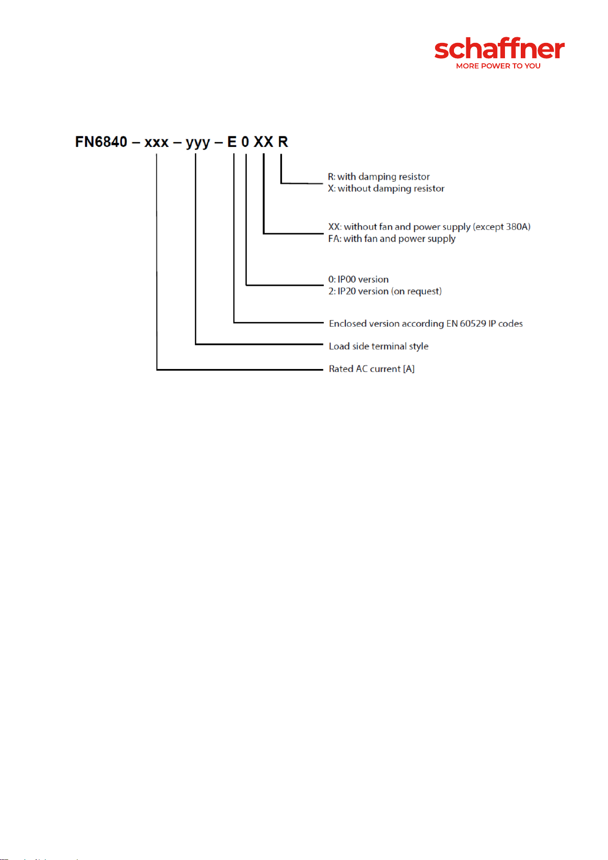
The standard FN6840 LCL filter series from Schaffner has the following key features:
▪Current and voltage range of 25 A … 380 A @ 50°C, up to 480 VAC 50/60Hz
▪Versions with or without resonance damping
▪Versions without cooling fan and without power supply (up to 250A)
▪Versions with cooling fan and with power supply (380A only)
▪Versions in IP00
▪Custom specific adaptations to fulfil dedicated requirements
Typical examples of regenerative motor drives applications:
▪Elevator, hoists and cranes, transportation systems
▪Machine tools, machines with frequent breaking cycles
▪Centrifuges, flywheels (when switched off)
▪Winder / Unwinder, rolling mills run-out tables
▪Press feeders
▪Test stands
Typical examples of other AIC applications:
▪Renewable energy, e.g. Wind generator or Photovoltaic inverter
▪Energy storage or battery charging systems
To fulfill customized application requirements please contact our local sales and support organization.
The LCL filter from Schaffner can be configured in different ways (with/without resonance damping,
with/without cooling fan).
This user manual is intended to support designers, installers, and application engineers with filter
selection, installation, application, and maintenance.
For additional support, please feel free to contact your local Schaffner sales and support organization.
ii. Important user notice
Schaffner LCL Filters are designed for the operation on the input (grid) side of power electronic
equipment with AFE (Active Front End) or AIC (Active Infeed Converter) in balanced three-phase power
systems, like typically used for AC motor drives and other converter systems. Filter suitability for a given
application must be determined by the user on a case-by-case basis. Schaffner will not assume liability

3/22 User and installation manual LCL Filters
for any consequential downtimes or damages resulting from the use of LCL Filters outside of their
specifications.
iii. General Safety Notes and Installation Guidelines
(Cautions and Warnings)
Schaffner LCL Filters delivery package contains the following important “General Safety Notes and
Installation Guidelines” which needs to be carefully read and understood before the product is being
installed.
Please contact your local Schaffner sales and support organization in case the document is not
contained within the delivery.

User and installation manual LCL Filters 4/22

5/22 User and installation manual LCL Filters
Table of Contents
1LCL filter designation......................................................................7
2Filter selection..................................................................................8
2.1 LCL Filter selection table FN6840 .................................................................. 8
2.2 Filter configurations without fan for forced cooling..................................... 8
2.3 Filter configurations with fan for forced cooling.......................................... 8
3Filter description..............................................................................9
3.1 General electrical specifications of LCL filter FN6840 ................................. 9
3.2 Additional electrical specifications................................................................ 9
3.2.1 Clearance derating by altitude............................................................................................... 9
3.2.2 Current derating by altitude................................................................................................. 10
3.3 Screw size, torque and cable cross-section requirement.......................... 10
3.3.1 Power terminals................................................................................................................... 10
3.4 Cooling requirement...................................................................................... 10
3.5 Damping resistors......................................................................................... 10
3.6 Circuit breaker ............................................................................................... 11
3.7 Mechanical frame sizes................................................................................. 11
3.8 LCL filter FN6840 footprint ........................................................................... 12
3.9 LCL Filter performance ................................................................................. 13
3.10 Drive settings.............................................................................................. 13
3.11 Functional diagram..................................................................................... 13
3.12 EMI-filter ...................................................................................................... 13
4Filter appearance and elements....................................................14
4.1 IP 00 version, frame size D - F...................................................................... 14
4.2 IP 00 version, frame size H (380 A only) ...................................................... 14
5Filter installation ............................................................................15
5.1 Step 1: Visual inspection .............................................................................. 15

User and installation manual LCL Filters 6/22
5.2 Step 2: Mounting............................................................................................ 15
5.3 Step 3: Wiring................................................................................................. 17
5.3.1 Verify safe disconnection of all line side power................................................................... 17
5.3.2 Carefully connect protective earth (PE) wire to adequate earth potential close to LCL filter.
17
5.3.3 Connect PE wire of LCL filter .............................................................................................. 17
5.3.4 Connect LCL Filters load side terminals L1’, L2’, L3’ to respective motor drive or rectifier
inputs. 17
5.3.5 Connect monitor switch TS- TS’.......................................................................................... 17
5.3.6 Connect LCL Filters line side terminals L1, L2, L3.............................................................. 18
5.3.7 Fuses................................................................................................................................... 18
6Filter maintenance .........................................................................19
6.1 Maintenance schedule .................................................................................. 19
6.2 Fan.................................................................................................................. 19
6.3 Power capacitors........................................................................................... 20
6.3.1 Note regarding the storage of capacitors............................................................................ 20
6.4 Electrical connections................................................................................... 20
7Troubleshooting.............................................................................21
8Abbreviation...................................................................................21

7/22 User and installation manual LCL Filters
1 LCL filter designation
The designation of the standard offering for LCL filter FN6840 are shown as follow:
Figure 1 LCL filter FN6840 designation
Examples of LCL filter designations:
FN6840-25-113-E0XXR: Filter for 50/60 Hz, up to 480 V AC grid, current rating 25A @50°C/50Hz, with
16mm2 terminals, open frame (IP 00), filter contains a damping module/resistors
FN6840-380-118-E0FAR: Filter for 50/60 Hz, up to 480 V AC grid, current rating 380A @50°C/50Hz,
with 240mm2 terminals, open frame (IP 00), with fan and power supply, filter contains a damping
module/resistors.

User and installation manual LCL Filters 8/22
2 Filter selection
LCL Filters need to be carefully selected and configured in order to fulfill the application requirements.
Therefore, please select the standard LCL filter only if the specification of the LCL filter FN6840 fulfills
your application needs. In case you have dedicated specifications to be fulfilled, please contact your
local Schaffner sales and support organization. Based on your feedback, Schaffner will check the
feasibility and provide you a customized proposal in case the requirement can be accomplished.
2.1 LCL Filter selection table FN6840
Filter*
Rated
current
@50°C
Typical motor
drive apparent
power**
400V/50Hz
Nominal
inductance
Nominal
capacity
Typical
power
losses***
Weight
Input/output
terminals
Frame
size
[A]
[kVA]
L1
[mH]
L2
[mH]
[µF]
[W]
[kg]
with RLC damping module:
FN6840-25-113-E0XXR
25
17
2.35
1.22
30
390
26
-113
D
FN 6840-50-115-E0XXR
50
35
1.18
0.61
60
580
47
-115
E
FN 6840-80-115-E0XXR
80
55
0.74
0.33
100
750
79
-115
F
FN 6840-160-118-E0XXR
160
110
0.37
0.17
200
1430
125
-118
H
FN 6840-250-118-E0XXR
250
170
0.24
0.11
300
1880
153
-118
H
FN 6840-380-118-E0FAR
380
260
0.15
0.07
500
3005
164
-118
H
without damping module:
FN 6840-25-113-E0XXX
25
17
2.35
1.22
30
360
24
-113
D
FN 6840-50-115-E0XXX
50
35
1.18
0.61
60
525
46
-115
E
FN 6840-80-115-E0XXX
80
55
0.74
0.33
100
660
77
-115
F
FN 6840-160-118-E0XXX
160
110
0.37
0.17
200
1250
123
-118
H
FN 6840-250-118-E0XXX
250
170
0.24
0.11
300
1595
148
-118
H
FN 6840-380-118-E0FAX
380
260
0.15
0.07
500
2625
159
-118
H
* Some rated current size might not be available now or on request only. Please contact your Schaffner sales for more information.
** Rated current @ 400 VAC/50 Hz. The proper power selection depends upon the drive specification, the motor and the
application requirements.
*** Losses calculated at 400 VAC/50 Hz and 3 kHz switching frequency
2.2 Filter configurations without fan for forced cooling
Frame sizes D, E, Fand H (up to 250 A) do not require air-flow for cooling hence they are not equipped
with a fan. The cooling with natural convection is enough if the filter is operating within its specification.
2.3 Filter configurations with fan for forced cooling
Frame size H (380 A) has an integrated ventilation with an fan and auxiliary power supply. For operating
the filter within its specification, the air flow of the forced cooling needs to be ensured within the cabinet.

9/22 User and installation manual LCL Filters
3 Filter description
3.1 General electrical specifications of LCL filter FN6840
Nominal operating voltage:
max. 480 VAC
Rated operating voltage:
max. 530 VAC
Operating frequency:
50/60 Hz
AFE/AIC Switching frequency:
3 kHz up to 10 kHz
Rated currents:
25 to 380 A
Rated inductance L2 (inverter/converter side):
8% @ 400V, 50 Hz and rated current
Rated inductance L1 (grid/line side):
4% @ 400V, 50 Hz and rated current
Overload capability:
1.6 x rated current for 1 min., ones per hour
Filter performance:
Prerequisite: Grid supply by insulated trans-
former
Remaining ripple current 1):
< 5% (max. ripplepk-pk vs. fundamentalpk-pk)
Line impedance:
Lgrid ≥ 1%
THDi2):
≤ 5% acc. EN61000-3-12
High potential test voltage: 3)
P →E 2480 VAC (1s)
Protection category:
IP 00 (IP20 on request)
Ambient temperature range:
-25°C to +45°C fully operational
>45°C to +70°C derated operation 4)
-25°C to +85°C transportation and storage
Flammability class:
UL 94V-2
Insulation class of magnetic components:
N (200°C)
Creepage and clearance distances:
According UL61800-5-1
Design corresponding to:
Filter: UL61800-5-1, EN61800-5-1
Chokes: EN61558-2-20 or EN60076-6
Temperature monitor output contact:
Thermal switch NC 180° C (UL-approved) to de-
tect overtemperature of chokes
1) for detailed resulting ripple current, please contact your local Schaffner office or partner.
2) the THDi acc. EN61000-3-12 or IEEE519 is not required for AFE applications as those standards refer to the harmonics of
the grid frequency generated by e.g. 6-pulse rectifier.
3) Repetitive tests to be performed at max. 80% of above levels, for 1 second.
4) Iderated = Inominal×√((70°C-Tamb)/20°C)
3.2 Additional electrical specifications
LCL Filters general electrical specifications refer to operating altitudes up to 2000m (6600ft) above sea
level.
Operation between 2000m and 4000m (6600ft and 13123ft) requires a derating for clearance and
current.
3.2.1 Clearance derating by altitude
Table 1 Altitude correction factors for clearances (extract from table A.2 in IEC 60664-1)
Altitude [m]
Normal barometric pressure
Multiplication factor for
clearances
[m]
[kPa]
2’000
80.0
1.00
3’000
70.0
1.14
4’000
62.0
1.29

User and installation manual LCL Filters 10/22
3.2.2 Current derating by altitude
The current derating is the factor to which the nominal current needs to be multiplied. A simplified
equation can be defined as function of ΔH (H –2000). This equation is valid for H up to 4000 meters
(ΔH = 2000 m).
Example: at an altitude of 3’500m, we get ΔH = 1’500m and the current derating = 0.9187. A filter with
a rated current of 100A can only be used up to 91.87A.
Remark: Do not use LCL Filters in altitudes above 4000m without consulting Schaffner first.
3.3 Screw size, torque and cable cross-section requirement
3.3.1 Power terminals
The cable cross-section must be selected according the rated filter input current, the maximum current,
the environment and other special requirement of the application. It should be stranded copper wire
cable with a temperature rating of ≥75°C. Recommended cable cross-section is given in Table 2. The
customer is fully responsible to define the most appropriate conductor type according to the application
and ensure a proper connection of the filter.
Table 2 LCL Filters power terminals designation
Terminal
designation
Screw
thread
Flex wire
AWG
Flex wire
[mm2]
Screw
torque value
[Nm]
Max width
cable lug*
[mm]
Frame size
-113
M6
6-18
0.75-16
3
15
D
-115
M8
1/0-8
10.50
8
15
E, F
-118
M10
3/0-500 kcmil
95-240
10
35
H
* Recommended connector type: wire or cable lug for 110 to 113, only cable lug for 115 to 118
** To fulfill creepage/clearance acc. UL 61800-5-1 without additional protection (insulation). Creepage/clearance can vary
depending on applicable standard and must be reviewed by customer. Creepage/clearance may be reduced when additional
protection (insulation) is provided.
3.4 Cooling requirement
Please note that only the 380A LCL Filters have an embedded fan and powered supply. The lower rated
LCL Filters do not require forced air cooling.
3.5 Damping resistors
The versions E0xxR have in use power resistors to ensure proper damping of the switching frequency.
The damping resistors are designed to dissipate the energy in the resonance circuit. Thus the damping
resistors can reach temperatures as high as 275°C!
Caution: risk of burning - do not touch the damping resistors during operation.

11/22 User and installation manual LCL Filters
3.6 Circuit breaker
The ratings 160, 250 and 380A have installed a circuit breaker in the capacitor circuit to ensure safe
capacitor disconnection in case of a short circuit. The capacitors can safely handle a short circuit current
of 10’000A, but for these filter size, in case of short-circuit, the current could reach higher values in the
trap circuit. This is why a safety device is installed to protect the capacitors.
For the ratings 25, 50 and 80A the impedance of the line choke is limiting the current to a value < 10 kA.
By default, the circuit breaker is set to status “on”.
Auxiliary contacts are provided along with the circuit breaker, with one NC normally closed and one NO
normally open contact. The NO auxiliary contact must be used in the control system to ensure the
interruption of the power branch the filter is connected to. The NC auxiliary contact is available to be
used for signaling and/or warning purpose.
The circuit breaker must never be switched-off manually when the application is in operation or under
voltage. There is a risk of electrical shock when doing so!
3.7 Mechanical frame sizes
The components of the LCL Filters FN6840 are implemented on a base plate or base frame with 4
different frame sizes, Frame D to Frame H, from the lowest to the highest rating. Dimensions and
footprint are provided in section 3.8.
Figure 2 Overview of all IP 00 frame size versions

User and installation manual LCL Filters 12/22
3.8 LCL filter FN6840 footprint
Figure 3 Mechanical Data of FN6840
Table 3 Dimensions of all frame sizes
Dimensions in [mm]
Dimensions in[in]
Frame
Drill pattern
Base
Volume
Drill pattern
Base
Volume
R
S
T
U
X
Y
Max. Z
R
S
T
U
X
Y
Max. Z
D
540
180
11
560
491
260
252
21.3
7.1
0.4
22.0
19.3
10.2
9.9
E
680
220
11
705
635
290
318
26.8
8.7
0.4
27.8
25.0
11.4
12.5
F
730
250
11
752
684
340
343
28.7
9.8
0.4
29.6
26.9
13.4
13.5
H
1115
390
11
1150
1053
462
456
43.9
15.4
0.4
45.3
41.5
18.2
18.0
For Dimensions without Tolerances: ISO2768-m/EN22768-m applies

13/22 User and installation manual LCL Filters
3.9 LCL Filter performance
The LCL filter can achieve its performance, if the LCL filter FN6840 specification is suitable to the
application requirements. Additional prerequisites are that the line side is supplied by a main isolation
transformer and that the grid impedance is ≥1%. Under those conditions and within the kept filter
specifications the remaining ripple current is < 5% (max.ripple currentpk-pk vs fundamentalpk-pk). THDi
according EN61000-3-12 is <5% in any case. This value shall be used just for reference only as that
standard is not applicable for LCL filter applications.
Schaffner strongly recommends, that the LCL filter version with damping module/resistors are used in
case the AFE motor drive or AIC has no active damping function. Only in case the drive has a working
active damping function, an LCL filter without a damping module would be tolerable.
3.10 Drive settings
The performance (stability, ripple current, phase shift) is highly dependent on the control parameters.
The setting of the parameter must be advised or done by a technical expert. It is not Schaffner’s
responsibility to set up the drive correctly to make the system work properly.
3.11 Functional diagram
LCL filter FN6840 with damping module:
LCL filter FN6840 without damping module
Filter terminals
Line L1/L2/L3
3 terminal blocks
Load L1’/L2’/L3’
3 terminal blocks
TS - TS
Connecting terminals to thermal switch NC 180°C (UL-
approved) to detect overload temperature in chokes
PE
Protective earth. Threaded stud with washer and nut
3.12 EMI-filter
When the LCL filter must be combined with an EMI-filter to fulfill an EMI-standard, your local Schaffner
office or Schaffner partner shall be contacted in order to support the selection of the matching product.
Note: be aware that not all EMI-filters are suitable due to unwanted resonances between LCL- and EMI-
filter

User and installation manual LCL Filters 14/22
4 Filter appearance and elements
The very compact and neat design of LCL filter FN6840 is realized by a two-level construction. The
principle filter construction of all frame size are identical, except the 380 A rating is equipped with a fan
and an auxiliary supply.
4.1 IP 00 version, frame size D - F
The general design of the IP 00 versions with damping module and without fan is shown in Figure 4.
The design and construction of the lower-level is shown in Figure 4 left. The line choke L1 and the
load choke L2 on the base plate, which contains screw holes for wall mounting. The power terminal,
the power capacitors and the resistors of the damping module are placed on the upper-level.
Figure 4 Design of LCL filter FN6840 (Type E0XXR, frames D to F): lower level left and upper-level right
4.2 IP 00 version, frame size H (380 A only)
The design of the LCL filter 380 A with fan- and aux. power supply module (E0FAR) is shown in Figure
5.
The design and construction of the lower-level is shown in Figure 5 left. The line choke L1 and the
load choke L2 on the base frame, which contains screw holes for wall mounting. The power terminal,
the power capacitors and resistors of the damping module and a circuit breaker are placed on the up-
per-level in Figure 5 right.
The fan module is visible at the lower level.
Figure 5 Design of LCL filter FN6840 (Type E0FAR, frame H): upper-level right and lower level left.

15/22 User and installation manual LCL Filters
5 Filter installation
Please follow the simple steps below to ensure a safe and reliable filter function for many years. Please
do also always follow the general safety and installation guidelines provided within this document as
well as relevant local, national or international standards that are applicable.
5.1 Step 1: Visual inspection
All Schaffner LCL Filters have undergone rigorous testing before they left our ISO 9001:2008 certified
factories. They are packaged with great care in a sturdy container for international shipment.
However, carefully inspect the shipping container for damage that may have occurred in transit. Then
unpack the filter and carefully inspect for any signs of damage. Keep the shipping container for future
transportation of the filter.
In the case of damage, please file a claim with the freight forwarder involved immediately and contact
your local Schaffner partner for support. Under no circumstances install and energize a filter with visible
transportation damage.
If the filter is not going to be put in service upon receipt, store within the original container in a clean, dry
location, free of dust and chemicals and with respect to named temperature limits, see section 3.1.
5.2 Step 2: Mounting
LCL Filters are best installed as close as possible to the AFE or AIC. Ideally they are mounted next to
the rectifier or motor drive inside the electrical cabinet or control room.
All LCL Filters FN6840 are designed for wall-mounting installation.
It is forbidden to mount LCL Filters in flat position or any other position than wall-mounting in
upward position (cable entry from the bottom) as stated in this manual.
Important:
In order to ensure sufficient air flow, keep a clearance
of min.150mm above and below the filter to walls or
other components.
Additional work to access the device, caused by not
respected clearance distances, will be accounted
separately.
It must be ensured that the environmental
temperature is kept below 50°C with appropriate
thermal management (e.g. cabinet cooling). Filter
operation in environments with higher temperatures
require a temperature derating.
LCL Filter
AFE/AIC
>150mm
>150mm
>100mm
>100mm

User and installation manual LCL Filters 16/22
II.1
Screw hole positions for wall mounted filters
(as indicated in Table 4):
Table 4 Dimensions of frame sizes
Frame
Drill pattern [mm]
R
S
T
D
540
180
11
E
680
220
11
F
730
250
11
H
1115
390
11
All dimensions in mm; 1 inch = 25.4mm
II.2
Screw selection: Schaffner recommends zinc coated hex ribbed
flange steel bolts. Respect filters weight for appropriate choice
of screws! Head diameters must not exceed these dimensions:
M6: d ≤14.2mm, M10: d ≤21.2mm
II.3
Filter placement:
1. Set screws loose into wall, leave 5mm distance from head to
wall.
2. Lift filter with appropriate crane, smallest types (up to 25kg)
may be lifted manually by two persons.
3. Place filter first onto lower screws…
4. ...then position it through backplane head openings on upper
screws.
5. Fix screws with appropriate torque (depending upon the ma-
terial of the back plane and local standards).
R
S
T
d
3.
4.

17/22 User and installation manual LCL Filters
5.3 Step 3: Wiring
5.3.1 Verify safe disconnection of all line side
power.
Consult your local safety instructions.
5.3.2 Carefully connect protective earth (PE)
wire to adequate earth potential close to LCL
filter.
Use a wire diameter of equal or bigger size as foreseen for
line/load side power cables –according to your local codes
and safety instructions.
LCL Filter
AFE/AIC
>150mm
>150mm
>100mm
>100mm
5.3.3 Connect PE wire of LCL filter
with appropriate cable lug to threaded stud.
| torque M5: 2.2 Nm
| torque M6: 4 Nm
| torque M8: 9 Nm
| torque M10: 19 Nm
| torque M12: 25 Nm
5.3.4 Connect LCL Filters load side terminals L1’, L2’, L3’ to respective motor
drive or rectifier inputs.
The third part of LCL Filters designation is a number contains three digits, i.e. FN6840-25-113, which
indicates power terminal type.
See section 3.3 for the recommended wire size and torque. Use stranded copper wire with a
temperature rating of 75°C or higher.
Note: In case the cables on the power terminals are installed without cable lug, it is recommended to
follow the maintenance manual closely. Maintenance manual is available on your request per Schaffner
contact.
5.3.5 Connect monitor switch TS- TS’
The monitor switch is a relay contact, which is open in
ALARM state. It is constituted by a thermal switch NC
180°C (UL-approved) to detect overload of chokes. It may
either be used to remotely disconnect the drive’s load via
respective input of drive control (check drive manual) or as
alarm sensor for system control unit.
AN ENGAGED MONITOR
SWITCH MUST LEAD TO
IMMEDIATE LOAD
SHUTDOWN AND
INVESTIGATION OF THE
PROBLEM.

User and installation manual LCL Filters 18/22
5.3.6 Connect LCL Filters line side terminals L1, L2, L3
Connect to power input protection (current limiting fuses –see below).
IP 20 enclosure cable wiring please refer to the remarks for the load side cable wiring (see 5.3.4).
5.3.7 Fuses
It is recommended to add external over-current protection for the LCL Filters. Table 4 shows requested
fuse current ratings for UL class J and for IEC class gG. The fuse rating is independent of the supply
voltage.
Table 5 Requested fuse current rating for UL class J and for IEC class gG
LCL filter rating
Fuse class J
Fuse class gG
All FN 6840
rated current [A]
rated current [A]
FN6840-25-113
40
35
FN6840-50-115
80
80
FN6840-80-115
150
125
FN6840-160-118
250
224
FN6840-250-118
350
300
FN6840-380-118
600
600

19/22 User and installation manual LCL Filters
6 Filter maintenance
LCL Filters described in this manual are equipped with long life components that ensure a satisfactory
function for many years under normal operating conditions. Any operation under extreme conditions
such as over-temperatures, overvoltage situations, polluted environments etc. reduces the life
expectancy. The following maintenance recommendations will help maximize filter lifetime.
Warnings:
High voltage potential is involved in the operation of this product. Always
remove line side power before attempting to perform maintenance and let
ample time elapse for the capacitors to discharge to safe levels (<42 V).
Residual voltages are to be measured both line to line and line to earth.
Line side power must be disconnected prior to replacement of any part.
6.1 Maintenance schedule
Table 6 Maintenance schedule
year
1
2
3
4
5
6
7
8
9
10
11
12
check and clean fan(s)
X
X
X
X
X
X
X
X
X
X
X
X
replace fan(s)
X
X
check & tighten el. Connections 1)
X
X
X
X
X
X
X
X
X
X
X
X
check el. values of capacitors
X
X
X
X
X
X
replace power capacitors
X
1) Only external connections need to be checked.
6.2 Fan
Schaffner LCL Filters are reliable low maintenance products. Many products like power supplies,
inverters or motor drives utilize fans for forced cooling to minimize size and weight. LCL Filters are
designed with a similar temperature management concept and therefore, fans may have to be
maintained and replaced in certain intervals to sustain the function and value of the product. Fans are
100% field replaceable without the need to uninstall and disconnect the filter.
Forced cooling devices are needed for the operation of Schaffner LCL Filters up to their nominal rating.
Such cooling devices must be checked and cleaned regularly (if installed) to always ensure sufficient
air flow.
Important: increased audible noise is a typical indicator of a fan that needs
maintenance or replacement. This could also occur outside of a maintenance
schedule.
Before cleaning or replacing the cooling devices, make sure to consult the recommended maintenance
procedures and schedules of the supplier of the cooling device in use.
This manual suits for next models
11
Table of contents
Other Schaffner Water Filtration System manuals

Schaffner
Schaffner FN 6840-25-113-E0XXR Operating manual

Schaffner
Schaffner Ecosine FN3446 Series Operating manual

Schaffner
Schaffner Ecosine max FN 3470 Operating manual

Schaffner
Schaffner FN5420 Operating manual

Schaffner
Schaffner FN 5060 Series Instruction sheet

Schaffner
Schaffner Ecosine FN34 Series User manual

Schaffner
Schaffner ECOsine User manual

Schaffner
Schaffner ecosine FN3540 User manual

Schaffner
Schaffner Ecosine evo FN3440 Operating manual

Schaffner
Schaffner ECOsine active FN3420-030-3 Series User manual