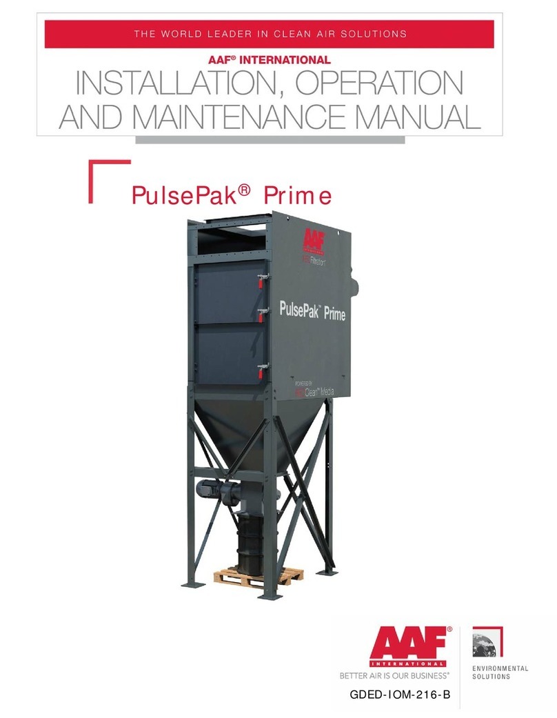
AAF FabriPulse BinVent User manual

GDED-IOM-217
© 2016 American Air Filter Company, Inc. Any use of the text or images
this document contains, without permission of American Air Filter
Company, Inc., is prohibited. FabriPulse and AAF are registered
trademarks of American Air Filter Company, Inc. d/b/a AAF
International.
FabriPulse BinVent

2
© 2016 American Air Filter Company, Inc. Any use of the text or images
this document contains, without permission of American Air Filter
Company, Inc., is prohibited. FabriPulse and AAF are registered
trademarks of American Air Filter Company, Inc. d/b/a AAF
International.
TO ORDER SPARE & REPLACEMENT PARTS
Call 1-800-477-1214
Email: [email protected]
Parts Sales
Power & Industrial
AAF International
9920 Corporate Campus Drive
Suite 2200
Louisville, KY 40223-5000
USA
Internet: http://www.AAFParts.com

3
© 2016 American Air Filter Company, Inc. Any use of the text or images
this document contains, without permission of American Air Filter
Company, Inc., is prohibited. FabriPulse and AAF are registered
trademarks of American Air Filter Company, Inc. d/b/a AAF
International.
TABLE OF CONTENTS
1INTRODUCTION ........................................................................... 5
2SAFETY......................................................................................... 5
2.1 Safety statement........................................................................ 5
2.2 Safe working practices and staff training ....................................... 5
2.3 Dust explosions.......................................................................... 6
2.4 Electrical hazards ....................................................................... 7
2.5 Rotating equipment .................................................................... 8
2.6 Safety guards ............................................................................ 8
3GENERAL PRODUCT INFORMATION.............................................. 8
3.1 Description ................................................................................ 8
3.2 Purpose and intended use............................................................ 8
3.3 Normal Operation ....................................................................... 9
3.4 Sizes......................................................................................... 9
3.5 Filter elements ........................................................................... 9
3.6 Weights....................................................................................10
4PRODUCT SHIPMENT...................................................................10
4.1 How the product ships................................................................10
4.2 Items that ship separately ..........................................................10
5PRODUCT RECEIPT AT THE DESIGNATED DELIVERY POINT.........10
5.1 Responsibilities of the customer or customer’s agent .....................10
5.2 Receiving .................................................................................10
5.3 Inspection on arrival ..................................................................10
5.4 Damaged goods ........................................................................11
5.5 Missing goods ...........................................................................11
6UNLOADING AND HANDLING ......................................................11
6.1 Unloading .................................................................................11
6.2 Handling...................................................................................12
6.3 Rigging and hoisting instructions .................................................12
7STORAGE AND PROTECTION .......................................................12
8SITE PREPARATION ....................................................................12
8.1 Locating equipment ...................................................................12
8.2 Anchoring.................................................................................13

4
© 2016 American Air Filter Company, Inc. Any use of the text or images
this document contains, without permission of American Air Filter
Company, Inc., is prohibited. FabriPulse and AAF are registered
trademarks of American Air Filter Company, Inc. d/b/a AAF
International.
9ASSEMBLY AND INSTALLATION ..................................................13
9.1 Introduction..............................................................................13
9.2 Filter Installation .......................................................................13
9.3 Fan Installation .........................................................................15
9.4 Electrical Connections ................................................................15
9.5 Compressed Air Connection ........................................................18
10 START-UP & OPERATION.............................................................18
10.1 Start-up checklist ......................................................................18
10.2 Normal operation ......................................................................18
11 MAINTENANCE ............................................................................19
11.1 Record Keeping .........................................................................19
11.2 Six months ...............................................................................19
11.3 Annual Maintenance...................................................................20
11.4 Filter removal and installation .....................................................20
11.5 Accessories...............................................................................21
12 TROUBLESHOOTING ....................................................................21
12.1 Poor pulse cleaning performance .................................................21
12.2 Visible Discharge (emission to atmosphere) ..................................22
12.3 Insufficient Extraction ................................................................23
13 RECOMMENDED SPARE PARTS LIST ............................................23

5
© 2016 American Air Filter Company, Inc. Any use of the text or images
this document contains, without permission of American Air Filter
Company, Inc., is prohibited. FabriPulse and AAF are registered
trademarks of American Air Filter Company, Inc. d/b/a AAF
International.
1INTRODUCTION
This document contains the information necessary to properly receive,
assemble, install, operate, and maintain the AAF®FabriPulse®BinVent filter system
and filters. The purchaser, installer, and operator of the filter system MUST read
and comply with this document in its entirety prior to installation of the equipment
and its operation. Failure to comply with the requirements of this manual may void
the product warranty. The information and guidelines contained in this manual are
not exhaustive, and additional or different precautions, measures, training, etc. may
be needed depending on the specific circumstances.
CAUTION
These instructions are specific to the AAF FabriPulse BinVent filter system and
filters. All ancillary tasks including, but not limited to, electrical and mechanical
work, equipment handling, and safety procedures must be performed in
accordance with industry accepted practice and all relevant local, state, and
federal government codes, laws, and policies.
2SAFETY
2.1 Safety statement
The air cleaning equipment supplied by AAF International ranges from very
large multiple-component assemblies which require significant and complex,
rigging, handling and assembly on-site, to small compact assemblies that are easily
handled and maneuvered. Many of the dust collectors will require electrical
connections, compressed air connections, and high speed rotating equipment.
When dealing with dust collection equipment, personnel safety must be the
highest priority of all involved, including riggers, installers, operators, users, and
maintenance personnel. Those responsible on-site shall review the details of the
equipment beforehand and develop a plan for dealing with all stages of the
installation, from receipt of the equipment on-site to start-up, commissioning, and
hand-over. All applicable health, safety, and environmental (“HSE”) rules,
regulations and legislation shall be fully complied with, at all times.
2.2 Safe working practices and staff training
AAF International is fully committed to the safety of its employees and those of
its customers. In this spirit the following guidelines are offered for the consideration
of those responsible:
All personnel shall receive safety training specific to the site, the task, and the
conditions under which the work will be conducted.

6
© 2016 American Air Filter Company, Inc. Any use of the text or images
this document contains, without permission of American Air Filter
Company, Inc., is prohibited. FabriPulse and AAF are registered
trademarks of American Air Filter Company, Inc. d/b/a AAF
International.
All personnel shall be equipped with appropriate safety apparel and equipment,
such as clothing, footwear, hard-hats, gloves, ear protection, eye protection, and
safety harness.
All personnel involved in any stage of the process shall have been trained for
the tasks in which they will be involved and at all times shall be under the direct
supervision of experienced supervisors and managers.
All personnel shall be equipped with appropriate tools and equipment to safely
and efficiently complete their task.
Adequate lighting shall be supplied at all times while work is being conducted.
A work perimeter shall be set up to define the limits of the area within which
the work will be conducted and outside which there will be no threat to the safety
of personnel or plant. The perimeter shall be taped-off and marked appropriately to
prevent accidental ingress of uninvolved personnel or equipment. When the work
area impedes into existing access ways or traffic routes for which no practical
alternative is available, barriers, wardens and flaggers shall be employed to safely
control crossing traffic and personnel.
At any time only those personnel directly involved in completing the task at
hand shall be allowed within the work perimeter.
2.3 Dust explosions
Dust explosions constitute a serious industrial hazard and may result in death,
serious injury, and/or devastating property damage. It is the responsibility of the
user to identify the nature of the dust and whether or not it poses an explosive
hazard and to properly mitigate this hazard. Except as otherwise expressly provided
in writing, AAF makes no representation or warranty in connection with explosion
hazard equipment, including, but not limited to, the necessity or effectiveness of
explosion hazard equipment or to the design, installation, operation, and
performance of such equipment. The basic standard for dealing with explosive dust
applications is from the National Fire Protection Agency (“FPA”), NFPA 69: Standard
on Explosion Prevention Systems. This standard applies to the design, installation,
operation, maintenance, and testing of systems for the prevention of explosions by
means of various methods. The user shall be fully conversant with the provisions of
NFPA 69 and shall comply in full with all of its requirements.

7
© 2016 American Air Filter Company, Inc. Any use of the text or images
this document contains, without permission of American Air Filter
Company, Inc., is prohibited. FabriPulse and AAF are registered
trademarks of American Air Filter Company, Inc. d/b/a AAF
International.
By its very nature AAF equipment is intended to be used to capture airborne
particulate matter, otherwise known as dust. There are various methods for dealing
with a dust explosion in a dust collector. These can include, but are not limited to,
the use of properly designed explosion vents, explosion suppression systems, or
flameless vents. The user shall understand which method is being used and who is
responsible for the design and supply of the equipment required.
When an explosive dust has been properly identified to AAF, the dust collector
may be structurally designed to withstand the internal pressure generated during
the explosive event and fitted with an explosion vent, or with multiple vents,
designed to safely discharge the pressure and the resulting fireball. The user shall
review the purchase order and the documents referenced within it to determine if
explosion protection equipment has been supplied by AAF International. Where this
is the case, review the appropriate sections of this manual that deal with the
installation, operation and maintenance of the equipment ordered.
When explosion protection systems are supplied by multiple vendors, it is the
responsibility of the user to coordinate between suppliers to ensure that the
equipment supplied by each vendor will work together to achieve the required
protection. For instance, if an explosion suppression system is being supplied by
parties other than AAF, it is incumbent on the user to ensure that the dust collection
equipment has been ordered to resist the internal pressure defined by the
suppression equipment supplier.
Dust collectors fitted with explosion vents must not be located indoors, unless
properly designed in accordance to NFPA regulations. The equipment shall be
oriented so that the vent will discharge to an unoccupied zone. Such a zone will be
prohibited to personnel and shall not include critical equipment or services such as
fuel storage tanks, flammable materials, fire hydrants, power distribution or
electrical control equipment, or similar. If the vent (or vents) are located on the
side(s) of the equipment the vent discharge area shall be isolated with barriers
erected to prevent the parking of vehicles, pedestrian use, or use of the area for
temporary storage. Warning signs shall be posted. Include diagrams showing the
distribution of a typical dust explosion discharge.
2.4 Electrical hazards
Before doing any work on the AAF equipment make sure that all potential
electrical hazards have been identified and that all electric current connected to the
equipment, and to any connected or associated equipment, has been properly
disconnected and securely locked-out to prevent accidental reconnection prior to

8
© 2016 American Air Filter Company, Inc. Any use of the text or images
this document contains, without permission of American Air Filter
Company, Inc., is prohibited. FabriPulse and AAF are registered
trademarks of American Air Filter Company, Inc. d/b/a AAF
International.
completion of the work. All electrical work shall be done in full accordance with the
current edition of NFPA 70, the National Electrical Code, and all other applicable
laws, rules, and regulations. All electrical work shall be performed by a licensed
electrician. Only original AAF parts shall be used as replacements for ongoing
maintenance and repair.
2.5 Rotating equipment
The FabriPulse BinVent can include a fan which is installed with the dust
collector. The fan wheel rotates and has the potential to cause severe injury. A fan
discharge guard is provided to help prevent access to the fan from outside the
housing, and should always remain in place. All due care should be exercised to
avoid any contact with the operating fan. The fan must be disconnected and locked
out prior to the performance of any maintenance work, see paragraph Error!
eference source not found..
2.6 Safety guards
When ordered with fan option, the FabriPulse BinVent will be supplied with a fan
outlet guard to help prevent access to the fan, from the outside of the unit.
Additionally, the housing should never be entered without taking precautions
outlines in paragraph 2.5.
3GENERAL PRODUCT INFORMATION
3.1 Description
The FabriPulse BinVent is a complete pulse-jet cartridge collector system
capable of providing continuous on-line cleaning. The innovative design allows quick,
tool-less access to all 6 filters, inside the fully sealed housing. The collector is
available in a standard configuration, where vertical cartridges are fully contained
within the powder painted housing, or in a drop-in version, where the majority of
the cartridge extends below the equipment mounting flange. Additionally, the
standard configuration can be provided with a side mounted fan. Available with
multiple media options, the collector’s small footprint can meet any low CFM need.
3.2 Purpose and intended use
The FabriPulse BinVent’s standard and drop-in configurations are designed
with silo venting and pneumatic transfer points in mind. The space saving foot
print will fit even the smallest silos needing filtration. The fan powered option
utilizes the same housing and equipment, and is intended for mechanical transfer
points needing filtration, where no fans are currently installed.

9
© 2016 American Air Filter Company, Inc. Any use of the text or images
this document contains, without permission of American Air Filter
Company, Inc., is prohibited. FabriPulse and AAF are registered
trademarks of American Air Filter Company, Inc. d/b/a AAF
International.
3.3 Normal Operation
In all configurations, the bottom flange would be sealed and bolted to the
installation, allowing rising air to enter the housing and cartridges. The non-
powered fan outlet is in the rear of the collector, and the fan powered outlet is
from the side mounted fan. Neither are intended to be connected to downstream
ductwork.
During filter element cleaning, a pulse controller automatically selects the
element or elements to be cleaned, activating solenoid valves which open air
diaphragm valves. High pressure air pulses directly into the center of the selected
element, or pair of elements, for 100 milliseconds, blowing collected dust off the
filter element(s). Gravity returns the particulate to the process stream below.
3.4 Sizes
The FabriPulse BinVent is built around a round vertical hanging cartridge that
is loaded from the clean air side of the equipment. All units are equipped with 6
filters, and multiple units can be used in tandem for higher CFM needs. Individual
applications require unique airflows, and the BinVent can handle these as well by
utilizing an outlet damper (provided on all provided fans) and by changing the
length of filters to create the exact media area required. Varying length filters are
not offered as standard.
3.5 Filter elements
The FabriPulse BinVent utilizes a hanging cartridge with
vertical pleats, ideal for maximizing filtration efficiency and
providing outstanding cleaning power. The standard media offering
is REDClean S media, our high efficiency spunbond polyester.
Additional media options are available to meet your application’s
need, including grounded/anti-static media, oleo-phobic and
hydrophobic media, and high efficiency PTFE coated membranes.

10
© 2016 American Air Filter Company, Inc. Any use of the text or images
this document contains, without permission of American Air Filter
Company, Inc., is prohibited. FabriPulse and AAF are registered
trademarks of American Air Filter Company, Inc. d/b/a AAF
International.
3.6 Weights
Model
Approx. Total Unit Weight
lb.
kg
BV-6
300
136
BVF-6
300
136
BVD-6
200
91
NOTE: This table is for guidance only. The collector delivered may vary,
according to a number of factors such as the addition of accessories or any other
custom changes.
4PRODUCT SHIPMENT
4.1 How the product ships
Typically, the Fabripulse BinVent dust collector will ship upright on a wooden
skid. The unit will ship using LTL (less than truckload) shipping unless otherwise
agreed with the buyer. Consult AAF International for information on carrier
arrangements.
4.2 Items that ship separately
AAF International may ship items separately. The customer will be notified
which equipment ships separately. Items that ship separately should be set aside in
an area that is clean, dry, and in a place where damage to the equipment will not
occur.
5PRODUCT RECEIPT AT THE DESIGNATED DELIVERY POINT
5.1 Responsibilities of the customer or customer’s agent
Ensure all loading/unloading equipment and safety equipment is on site at the
time of delivery. Safe and efficient operation of the collector depends on proper
installation. Know proper laws, codes and regulations before installation starts.
5.2 Receiving
Remove crates, tarps, shipping straps, etc. along with any loose items or
equipment before unloading the AAF FabriPulse BinVent.
5.3 Inspection on arrival
The AAF FabriPulse BinVent is normally shipped by truck and should be checked
for damage that may have occurred in route. Compare the collector(s) received to
the description and/or drawing of the collector(s) ordered. Immediately report any

11
© 2016 American Air Filter Company, Inc. Any use of the text or images
this document contains, without permission of American Air Filter
Company, Inc., is prohibited. FabriPulse and AAF are registered
trademarks of American Air Filter Company, Inc. d/b/a AAF
International.
differences or missing items from the order to AAF International. Remove loose
items or components before lifting the collector from the truck.
A qualified installation and service company should complete installation of the
collector and accessories.
5.4 Damaged goods
If there is any visible damage to the packaging or the equipment notify the
carrier and AAF before proceeding further and, if appropriate, file an immediate
claim with the carrier against such damage. Be aware that damage to packaging
may indicate hidden damage to the product that is not immediately discernable.
Digital color photographs must be taken of any damage to the packaging and
the equipment immediately on discovery. The nature of any damage must also be
documented in writing. Adequate documentation will be critical to support any
claims.
Contact AAF International for claim filing procedure.
5.5 Missing goods
Any missing goods should be noted on the delivery receipt, and the carrier and
AAF notified immediately. Contact AAF International for claim filing procedure.
6UNLOADING AND HANDLING
6.1 Unloading
Failure to lift the collector correctly can result in severe personal injury,
property damage, or even death.
Connect lifting sling to at least four cabinet lifting lugs, distributing the load
evenly.
Use clevises, not hooks, on lifting sling.
Use of spreader bars is recommended on all lifting slings.
Check the drawings of the specific FabriPulse BinVent ordered for dimensions
and weights to ensure proper lifting and installation equipment.
All lifting operations must be made in compliance with the relevant HSE
legislation.

12
© 2016 American Air Filter Company, Inc. Any use of the text or images
this document contains, without permission of American Air Filter
Company, Inc., is prohibited. FabriPulse and AAF are registered
trademarks of American Air Filter Company, Inc. d/b/a AAF
International.
6.2 Handling
Only personnel experienced in handling equipment shall be employed for this
task.
It is recommended that each item of equipment remain on its pallet until it
has been moved to its final installation location. The FabriPulse BinVent may be
moved using a forklift to lift the product using its shipping pallet, if available. If
lifted by its shipping pallet, attention must be paid to properly balance the load
and strapping it to the handling device. Care shall be taken to ensure that the
equipment is not dropped or subjected to any impact loads.
6.3 Rigging and hoisting instructions
Only personnel experienced in rigging and hoisting equipment shall be
employed for this task.
The FabriPulse BinVent has lifting lugs mounted on the sides of the unit.
These may be used to hoist the product into its installation position. All lifting lugs
must be used when hoisting the product, spreader bars must be used at all times.
Position the spreader bars so that the force applied to each lifting lug is vertical
and not angled. Also make sure that lifting straps or cables do not come into
contact with any other part of the product to prevent the possibility of damage
from abrasion. Before hoisting, make sure that the load is properly balanced.
7STORAGE AND PROTECTION
In the event that the equipment is not placed in service within 30 days after
receipt, the filter cartridges must be removed and stored in a clean, dry place to
prevent possible moisture accumulation in the media.
8SITE PREPARATION
8.1 Locating equipment
The dust collector site location must take into account the wind and seismic
loadings. See collector specifications to ensure proper site location.
Ensure local laws, codes and regulations are followed for the materials being
collected. Noise levels should be considered when selecting the proper location of
the FabriPulse BinVent.
Locate the FabriPulse BinVent in a location so that maintenance to the collector
can be handled easily. See collector drawing for cartridge clearance.

13
© 2016 American Air Filter Company, Inc. Any use of the text or images
this document contains, without permission of American Air Filter
Company, Inc., is prohibited. FabriPulse and AAF are registered
trademarks of American Air Filter Company, Inc. d/b/a AAF
International.
In the case of hazardous dust, consult your local authorities, laws, codes, or
regulations for the location of the unit.
8.2 Anchoring
The FabriPulse BinVent is designed to be mounted on top of silos or
pneumatic transfer points. Mounting flanges with holes drilled to match customer
specifications are provided. Refer to the specific FabriPulse BinVent collector
drawing for bolt pattern and location.
9ASSEMBLY AND INSTALLATION
9.1 Introduction
Safe and efficient operation of the FabriPulse BinVent depends on proper
installation.
Authorities with jurisdiction should be consulted before installing the
FabriPulse Binvent to ensure local installation laws, codes, regulations and
procedures are followed.
A qualified installation and service agent must complete installation and
service of the dust collector and equipment.
Ensure all covers from shipping and loose materials are removed from the
collector before installation. Failure to do so can result in failure of the dust collector.
Ensure the hardware on the dust collector assemblies are properly installed
and tight before installation.
Apply silicone sealant to the bottom of the collector flange before mounting to
the silo or intended location. Ensure sealant circles around each bolt hole. Lift the
collector using its lifting lugs and lower into position at the installation location so
that the holes in the matching flanges correctly align.
9.2 Filter Installation
Cartridge filters for the FabriPulse BinVent are shipped separately, and must
be installed before operating the unit. To install the cartridges, follow the
instructions as follows:
1. To open the lid of the collector, disengage the 2 hold down latches on the
front of the unit, and lift up on the handle provided.

14
© 2016 American Air Filter Company, Inc. Any use of the text or images
this document contains, without permission of American Air Filter
Company, Inc., is prohibited. FabriPulse and AAF are registered
trademarks of American Air Filter Company, Inc. d/b/a AAF
International.
2. To secure the lid in the open position, engage the locks via the latches on
the side at the rear of the unit, as show below.
3. Open the hold down mechanism by pulling the knob shown below, and
turning 90 degrees. Then, lift via the handles provided.
4. Unpack and inspect new filters for any damage during shipping, storage,
or handling. DO NOT use damaged filters.

15
© 2016 American Air Filter Company, Inc. Any use of the text or images
this document contains, without permission of American Air Filter
Company, Inc., is prohibited. FabriPulse and AAF are registered
trademarks of American Air Filter Company, Inc. d/b/a AAF
International.
5. Drop in the new filters. While installing, be careful that the filters do not
contact the housing or any other objects which might damage or
puncture the filter surface.
6. Ensure that the flange of the filter is seated fully around the opening.
7. Close the hold down mechanism and turn the knob 90 degrees to lock
the mechanism in place.
8. Release the pull handles on the sides of the unit.
9. Close the lid carefully and secure the latches.
9.3 Fan Installation
For some units, a fan is supplied with the FabriPulse BinVent. If this is the
case, the fan must be installed in accordance with the drawings provided with your
order.
Mount the fan as shown on the drawing on the fan platform. Connect the fan
to the flexible inlet boot, and clamp the boot to the fan and collector using the
provided hose clamps.
9.4 Electrical Connections
WARNING: Potential shock hazard. Disconnect power before servicing. Only
qualified electrical personnel should work on this system.
The FabriPulse BinVent comes fully assembled with a pulse controller in a
NEMA4X enclosure mounted to the unit. Different NEMA ratings are available as an
option. Do not install in classified hazardous locations without an enclosure
suitably rated for the application and location.
The pulse control supplied with the FabriPulse BinVent is the Goyen IS-
DC12X Sequencer. This sequencer only operates in continuous pulsing mode.
To power the sequencer, connect power line to L1 and L2 as shown in the
wiring diagram below. Connection from the sequencer to the solenoid valves is
factory installed with the unit. The pulse controller can be powered with 120/240
VAC connection.

16
© 2016 American Air Filter Company, Inc. Any use of the text or images
this document contains, without permission of American Air Filter
Company, Inc., is prohibited. FabriPulse and AAF are registered
trademarks of American Air Filter Company, Inc. d/b/a AAF
International.
If a fan is provided with the collector, the fan requires field wiring and power
by the customer. The supplied fan requires 3 phase 208-230/460V connection. A
fan stop input is provided within the sequencer. This input is used to stop the
controller remotely. It may be connected to the blower fan control so the cleaning
cycle automatically pauses in the even the fan stops. Maximum cable size is 14-26
AWG.

17
© 2016 American Air Filter Company, Inc. Any use of the text or images
this document contains, without permission of American Air Filter
Company, Inc., is prohibited. FabriPulse and AAF are registered
trademarks of American Air Filter Company, Inc. d/b/a AAF
International.
When setting up the sequencer, the pulse duration and time between pulses
can be manually programmed to suit your need. To enter programming mode,
follow these steps:
1. Press Select, Up, Down, Up, Select
2. The ‘dP Low’ LED should now be lit.
3. Press Down or Up to scroll through the list.
4. The LED indicates the function to be programmed.
5. Press Select to change the settings for that function.
To set the pulse duration, enter programming mode, and press Select
when the ‘On Time’ LED is lit.
1. The LED should start to flash, indicating it is in programming mode.
2. Use the Up and Down buttons to select the On Time in milliseconds
between 30 milliseconds and 990 milliseconds, in increments of 10ms.
NOTE: A standard setting is between 150 and 250 milliseconds.
3. Press Select to confirm the setting.
To set the time between pulses, enter programming mode, and press Select
when the ‘Off Time’ LED is lit.
1. The LED should start to flash, indicating it is in programming mode.
2. Use the Up and Down buttons to select an Off Time in seconds,
between 60 seconds and 999 seconds. NOTE: The Off Time should not
be set lower than 60 seconds. The solenoids must have a 60 second
rest between pulses.
3. Press Select to confirm the setting.
If your collector is equipped with a fan, blowdown cycles can be initiated
when the fan powers off. The sequencer can be manually programmed to set the
number of blowdown cycles when the fan power is off. To set the number of
blowdown cycles, press Select when the ‘Blowdown Cycles’ LED is lit.
1. The LED should start to flash, indicating it is in programming mode.
2. Use the Up and Down buttons to select the number of blowdown
cycles you require, between 0 and 10.
3. Press Select to confirm the settings.
To enter normal operation, and exit programming mode, press Select when
the ‘Run’ LED is lit. This will automatically exit Programming Mode and save your
settings.

18
© 2016 American Air Filter Company, Inc. Any use of the text or images
this document contains, without permission of American Air Filter
Company, Inc., is prohibited. FabriPulse and AAF are registered
trademarks of American Air Filter Company, Inc. d/b/a AAF
International.
9.5 Compressed Air Connection
The FabriPulse BinVent dust collector requires dry compressed air (-40°F
dew point at 90-100 psig) for cleaning. Do not use over 100 psig of compressed
air. Solenoid valves will not operate and can cause damage to collector
components.
Connect the compressed air to the installed regulator via a 3/8” NPT
connection.
10 START-UP & OPERATION
10.1 Start-up checklist
Check the compressed air supply to the FabriPulse BinVent to ensure correct
and safe connection to the compressed air manifold. If supplied, connect the
compressed air to the filter regulator. Turn on the compressed air supply to the
manifold. Pressure available should be 90-100 psig.
Check that the filters are properly installed and that the round knob on the
hold down mechanism is locked in place (see section 9.2).
Energize the pulse controller and ensure the correct mode and parameters
are set (see section 9.4).
Listen for firing of the solenoids and diaphragm valves to determine that
they are all operational. Note that as each solenoid is activated, a “click” can be
heard. When the diaphragm valve is activated, a small jet of air vents from the
hole at the solenoid valve base and there will be a sharp noise as the compressed
air is allowed to escape from the compressed air manifold.
If necessary, energize the fan. If supplied, refer to the control wiring
diagram for proper connection.
10.2 Normal operation
The operation of the FabriPulse BinVent is fully automatic and does not
require constant supervision.
For successful operation of the FabriPulse BinVent, it must be ensured that:
1. A suitable, dry compressed air supply to the compressed air manifold
is available and connected to the controller at all times.
2. The power supply to the pulse controller is on.

19
© 2016 American Air Filter Company, Inc. Any use of the text or images
this document contains, without permission of American Air Filter
Company, Inc., is prohibited. FabriPulse and AAF are registered
trademarks of American Air Filter Company, Inc. d/b/a AAF
International.
3. The fan, if applicable, is operating at the specified conditions.
A record of operational data should be made and kept up to date. This is
covered in the maintenance section of this manual.
11 MAINTENANCE
11.1 Record Keeping
It is suggested that a record is kept of operational data and that all servicing
maintenance is recorded.
Maintenance data to be recorded should include details of inspections and any
parts replaced.
The following maintenance intervals are recommendations by AAF, your dust
collection system may need more or less frequent maintenance plans.
11.2 Six months
Examine the filters for any wear, damage, or excessive deposition of dust. If
the filters appear to be fully covered in dust and pulsing no longer adequately
cleans them, the filters need to be replaced. Replacement of the filters should
occur as soon as possible.
Examine the lid gasket seal for wear.
Examine the filter hold down mechanism for wear.
Inspect all joints for evidence of air or dust leakage.
Check for evidence of moisture or dust build up within the collector. Moisture
in the collector can cause plugging and premature filter failure.
Check all electrical apparatus for proper operation.
Check for correct operation of solenoid valves.
Check discharge air area for signs of dust. See Troubleshooting if bypass
occurs.
Check all safety & warning labels are intact and legible and secure.

20
© 2016 American Air Filter Company, Inc. Any use of the text or images
this document contains, without permission of American Air Filter
Company, Inc., is prohibited. FabriPulse and AAF are registered
trademarks of American Air Filter Company, Inc. d/b/a AAF
International.
11.3 Annual Maintenance
Remove the diaphragms and inspect the valves for wear. Replace them with
new items if required.
NOTE: a replacement diaphragm and valve are supplied in the diaphragm
replacement kit.
Remove the used solenoids from within the solenoid box enclosure and
replace them with new items if required.
NOTE: AAF recommends having a spare set of diaphragm and solenoid kits
available at all times.
Inspect all gaskets and panels for possible leak points. Replace gaskets and
re-caulk panels as necessary.
11.4 Filter removal and installation
Disconnect power and lock out any electrical power sources before servicing.
CAUTION: Dirty cartridges may be heavy, use caution when removing the
cartridges from the dust collector.
Do not operate the dust collector with missing or damaged filters.
The working area requires good ventilation. Some applications involve
hazardous gasses and dusts. Check with an authorized person before work
commences to avoid exposure to hazardous substances. Appropriate PPE should
be considered and worn.
In order to minimize escape of dust particles which have been deposited in
the filters, it is recommended the used filters are placed into polyethylene sacks as
they are withdrawn from the unit for ultimate safe disposal.
Procedure:
1. Ensure that protective personal equipment (PPE) is worn, which may
include, but not limited to, protective clothing, breathing masks or
breathing apparatus, head, hand, eye and ear protection, approved
footwear.
2. Ensure that a sufficient quantity of polyethylene sacks is available.
3. Turn off the compressed air and run the pulsing sequence allowing
time for the compressed air in the manifold to be fully exhausted.
Table of contents
Other AAF Water Filtration System manuals
Popular Water Filtration System manuals by other brands

onga
onga PCF60 owner's manual

Water Filters Australia
Water Filters Australia K-B-VANITY owner's manual

HYDAC FILTER SYSTEMS
HYDAC FILTER SYSTEMS FAM 5 Operating instruction

PREMIER TECH
PREMIER TECH ECOFLO owner's manual

PREMIER TECH
PREMIER TECH Ecoflo Series owner's manual

PEP
PEP CL Series operating & maintenance manual

BWT
BWT AQA therm MOVE Power Installation and operating manual

Terra Universal
Terra Universal WhisperFlow Installation and operating guide

Philips
Philips IronCare GC024 user manual

Atlas Copco
Atlas Copco OSC 35 Instruction book

Veolia
Veolia Hydrotech Discfilter HPF2200 Series Operation and maintenance manual

AC Infinity
AC Infinity AC-RCF4 user manual