USBCam2 User Guide B1051061 Rev. –
iii
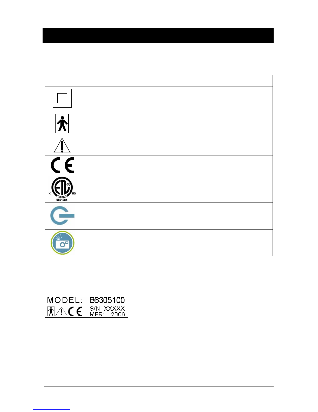
Safety Issues
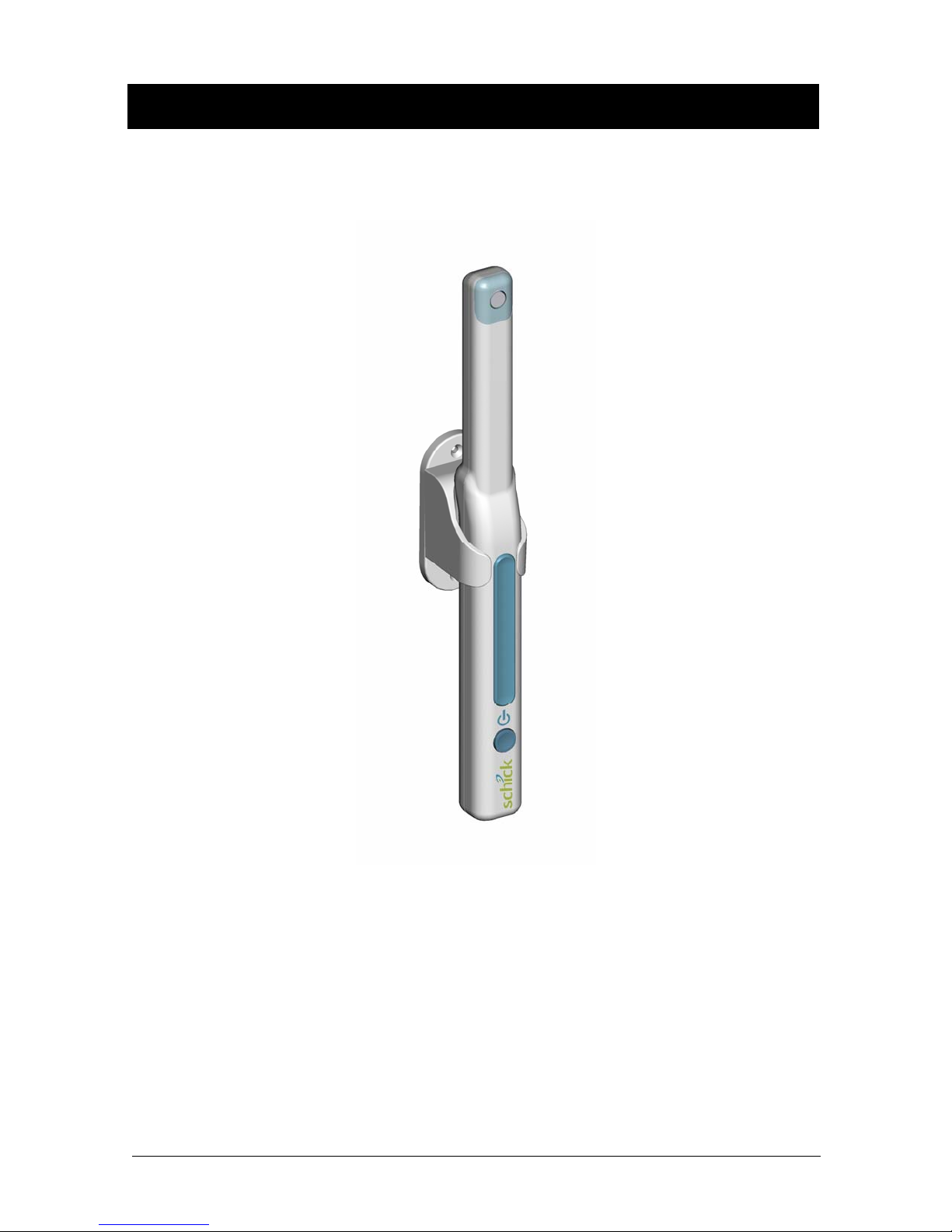
Check USBCam2 before Using It
There are no customer-serviceable components in the USBCam2. However, before each usage, check the
outer surface of the USBCam2 for any signs of physical damage or defect. The surface of the USBCam2
should have a smooth finish, with no evidence of chipping or damage to either the handpiece housing or the
lens section. If detected, contact your local distributor of Schick Technologies products for further
instructions.
To help ensure proper hygiene and to protect against infectious disease, refer to the Protective Measures
section of this document and observe all device cleaning and patient protection recommendations specified
there.
Avoid Excessive Temperatures when Using USBCam2
When in use, the LEDs in the USBCam2 may generate surface temperatures in excess of 106° F (41° C). To
avoid the potential risk of burn, do not use the USBCam2 in a single hand-held position for a prolonged
period. As an additional safety measure, the USBCam2 is equipped with an Auto-Off feature. This feature
turns off the camera automatically after 5 minutes of continuous use. The camera can be turned back on by
simply pressing the ON/OFF button on the handpiece.
Operate the USBCam2 as Directed
Always use the USBCam2 in accordance with the directions and recommendations contained in this User
Guide. Do not attempt to modify the USBCam2 or use it in system configurations not specified in this
document.
RF Interference Considerations
Although the USBCam2 equipment is designed to provide a reasonable degree of protection from
electromagnetic interference, according to IEC International regulations, it must be installed at an adequate
distance from electricity transformer rooms, static continuity units, two-way amateur radios and cellular
phones. To ensure proper operation, the latter (meaning, electricity transformer rooms, static continuity units,
two-way amateur radios and cellular phones) can be used only at a minimum distance of 5 feet (1.5m) from
any part of the USBCam2 system.
Any instrumentation or equipment for professional use located near USBCam2 must conform to
Electromagnetic Compatibility regulations. Non-conforming equipment, with known poor immunity to
electromagnetic fields, may not operate properly unless they are installed at a distance of at least 10 feet (3m)
and supplied by a dedicated electric line.
Apply Recommended Procedures for Cleaning the Equipment
Safe and proper operation of the equipment requires that a regular schedule of preventive maintenance be
followed. Refer to the Protective Measures section of this manual for details.
Do Not Connect Items that are Not Part of the System
Only items specified for use with the equipment are to be connected to the system. The equipment should not
be used adjacent to other equipment that is not part of the system. If, however, use with adjacent equipment
is necessary, normal operation should be observed and verified in that configuration.