manuals.online logo
Brands
  1. Home
  2. •
  3. Brands
  4. •
  5. Schier
  6. •
  7. Plumbing Product
  8. •
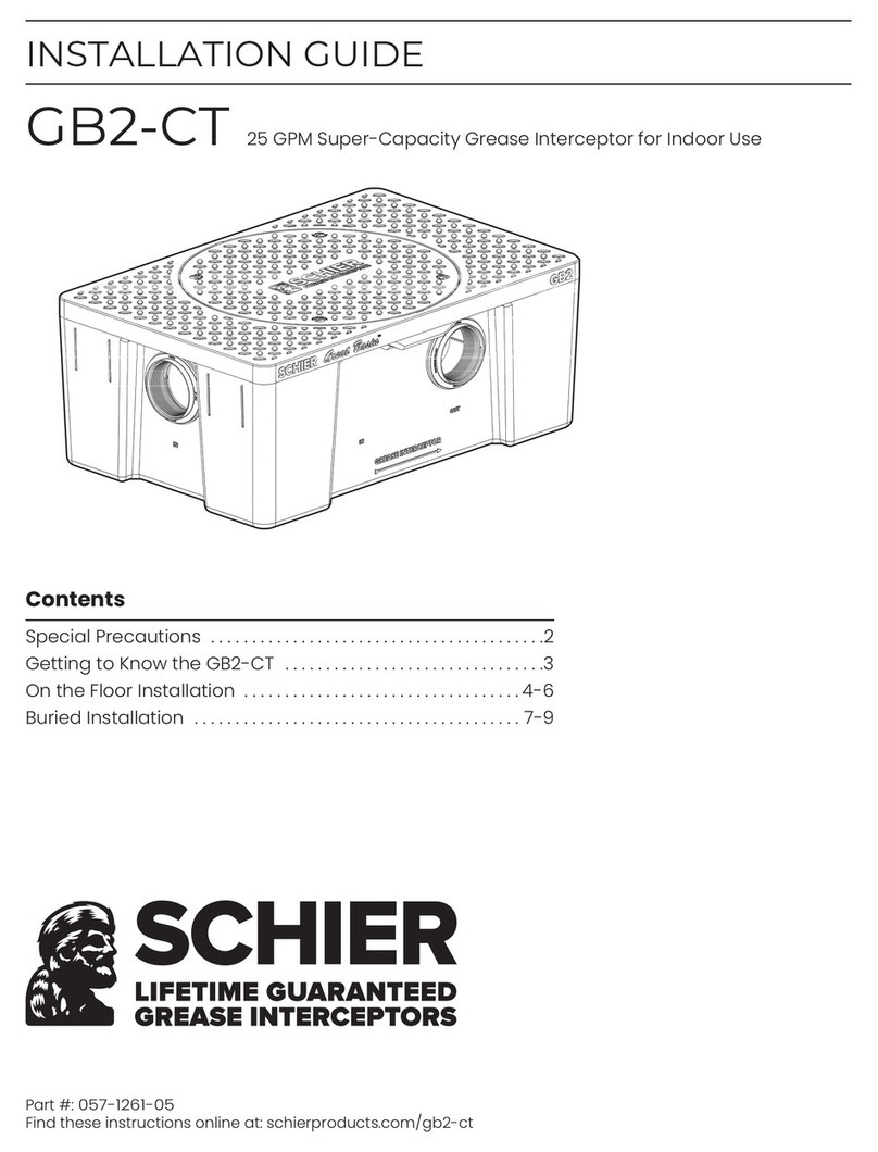
  9. Schier FCR2 User manual

Schier FCR2 User manual

Contents
Specifications . . . . . . . . . . . . . . . . . . . . . . . . . . . . . . . . . . . . . . . . . . . 1
Special Precautions . . . . . . . . . . . . . . . . . . . . . . . . . . . . . . . . . . . . . 2
Getting to Know the FCR2 . . . . . . . . . . . . . . . . . . . . . . . . . . . . . . . 3
Installation . . . . . . . . . . . . . . . . . . . . . . . . . . . . . . . . . . . . . . . . . . . . 4-8
SPECIFICATION AND INSTALLATION GUIDE
FCR2 Field Cut Riser System
For Use with Grease Interceptors Models GB-500,
GB-1000, GGI-750, GGI-1000 and GGI-1500
9500 Woodend Road | Edwardsville, KS 66111 | Tel: 913-951-3300 | www.schierproducts.com © Copyright 2019 Schier, All Rights Reserved
MODEL NUMBER:
FCR2
DESCRIPTION: 34" Field Cut Riser System
PART #: 8010-006-01 DWG BY: B. Karrer DATE: 9/3/2019 REV: ECO:
Notes
TOP VIEW
SIDE VIEW
SECTION A-A
ø 27-1/2"
ø 24-3/16"
ø 23"
32-1/2"
1"
6" TYP
1" TYP
Cut
Lines
A
A
Riser Height Needed Risers Required
(per accessway)
0" - 4" None (use adapter)
>4" - 34" FCR2
>34" - 64" FCR2 (x2)
>64" - 94" FCR2 (x3)
1. Unit weight: 32 lbs.
2. Riser not designed to hold water
Engineer Specification Guide:
Field-cut adjustable riser system to consist of injection molded polypropylene
body, 100% Silicone Sealant for assembly of riser components, butyl mastic sealant
for tank-riser or riser-riser joints, stainless steel fastening hardware and heavy duty
nylon cable ties and mounts. Riser shall allow field adjustability of cover to grade.
Installation Note
Minimum install height: 4". Maximum install height: 34". Riser system may be
stacked no more than three units high to a maximum of 94" extension. Access to
internal components will not be compromised.
Page 2 of 9
FCR2 Installation Guide
When Installing Interceptor Inside
Fernco or similar
rubber flow
restriction end cap
SPECIAL PRECAUTIONS
Installation Instructions
Hydrostatic Slabs (or Pressure Slabs)
High Temperature Kitchen Water
concrete slab subject to hydrostatic pressure
watertight
concrete
vault
Interceptor
Interceptor
Interceptor
Do not install this unit in any manner
except as described in these instructions.
Doing so may result in property damage, personal injury or death.
installation
instructions
DO NOT AIR TEST UNIT OR RISER SYSTEM!
For Schier Grease Interceptor Installations - Failure to follow this guidance
voids your warranty
cold water supply line
high temperature
effluent ( > 150º F)
approved backflow
prevention assembly
DTV (drain water
tempering valve)
directly connected indirectly connected
Interceptor
Interceptor
Interceptor
Interceptor
Interceptor
Interceptor
If water is entering the interceptor at excessive temperature (over
150º F), a drain water tempering valve (DTV) and approved backflow
prevention assembly must be installed. Most state and local
plumbing codes prohibit water above 150º F being discharged into
the sanitary sewer. Water above 150º F will weaken or deform PVC
Schedule 40 pipe, poly drainage fixtures like interceptors and erode
the coating of cast iron (leading to eventual failure).
Installation instructions and additional
components are included with the
interceptor. Read all instructions prior
to installation. This interceptor is
intended to be installed by a licensed
plumber in conformance with all
local codes.
If your dishwashing sink(s)
discharges into a floor
drain/sink (drain), you
must regulate the flow into
the drain to avoid an
overflow of water onto the
kitchen floor. This can be
done by installing a valve
or flow restriction cap on
the sink piping that
discharges into the drain.
See drawing for guidance. For detailed guidance on indirect
connections, go to:
webtools.schierproducts.com/Technical_Data/Indirect_Connections.pdf
When installed under a
hydrostatic slab (slab
designed to withstand
upward lift, usually
caused by hydrostatic
pressure) interceptor
must be enclosed in a
watertight concrete vault.
Page 3 of 9
FCR2 Installation Guide
SPECIAL PRECAUTIONS
AGS2
The wet weight of the interceptor combined
with high temperature kitchen water
creates the potential for tank deformation
when installed above grade. Model GB-500
installed above grade must be installed
with Above Grade Support Kit model AGS2
to maintain structural integrity
Above Grade Installation Support
(for Model GB-500 Only)
Install unit on solid, level surface in
contact with the entire footprint of
unit base; for suspended
installations design trapeze to
support the wet weight of the unit.
Do not partially support unit or
suspend unit using metal
U-channel to create a trapeze.
Fully Support Base of Unit
For above grade installations ensure
heavy inlet and outlet piping (such as
cast iron or long runs) is properly
supported or suspended during the
entire installation process to prevent
connection failure or damage to
bulkhead fittings.
Support Inlet and Outlet Piping
pipe supports
Interceptor
Interceptor
Interceptor
concrete floor
suspended installation
Interceptor
Interceptor
Interceptor
DO NOT
COMPACT
BACKFILL
For Schier Grease Interceptor Installations - Failure to follow this guidance
voids your warranty
High Water Table Installations
Interceptors and risers are not designed
to withstand water table height in
excess of the top of the unit when buried
(see figure). If it is possible for this to
occur, install the interceptor and risers in
a water-tight concrete vault or backfill
with concrete or flowable fill (wet
concrete and flowable backfill should be
poured in stages to avoid crushing the
interceptor). At risk areas include but are
not limited to tidal surge areas,
floodplains and areas that receive
storm water. Great Basin™ models that
are direct buried in high water table
scenarios must be installed with an anchor kit. Models GB-50, GB-75,
and GB-250 use model AK1 anchor kit. Model GB-500 uses model AK2
anchor kit for use with deadmen anchors. Models GB-1000, GGI-750 and
GGI-1500 use model AK3 anchor kit for use with deadmen anchors.
max water table height
for direct burial
deadman anchor
polyester strap
turnbuckle
Interceptor
Interceptor
Interceptor
GETTING TO KNOW THE FCR2
1. #8 x 5/8" Riser Body Assembly Screw (x12)
2. Riser Body Half (x2)
3. 100% Silicone Sealant
4. #10 x 3/4" Phillips Head Stainless Steel Screws (x4)
5. Cable Tie Mounts(x4)
6. Heavy Duty 18" - 120 lb. Cable Tie (x4)
7. Stainless Steel Eyebolt and Nut (x4)
8. 1" square x 80" block butyl mastic sealant
Page 4 of 9
FCR2 Installation Guide
2
2
4
5
6
7
4
5
6
7
1
8
3
6
4
5
7
6
7
4
5
1
Read all instructions
before installation
Install in conformance
with all local codes
2
Special Precautions
DO NOT AIR TEST UNIT OR RISER SYSTEM!
Doing so may result in property damage,
personal injury or death.
1
Do not add any form of lubricant
to riser tube during installation.
3
INSTALLATION
3 Risers (94") Max
4
Interceptor
Interceptor
Interceptor
Max Water Level
Risers are not designed to retain water
5
Make Sure Parts Are Clean When
Applying Silicone or Mastic Sealant
6
Tools You Will Need
#2 Phillips Head
Screwdriver
Tape
Measure Reciprocating Saw,
Circular Saw or Jigsaw Drill with
1/2" Chuck 1/4" Drill Bit
Level
7/16" Nut
Driver Bit
INCLUDED WITH GB-500
Grease
Pencil
Determine Trim Length (round up all fractions to next inch).
Only one FCR2 riser per cover will need to be cut.
NOTE: If trim length is 0 or less, no cutting is required. Trimming risers using
these guidelines will result in risers that are 0-2" shorter than the exact riser
height needed. Cover Adapter adjustability will allow for final adjustments
to grade.
1b
1Determine riser height needed and trim risers.
Measure dimension X to determine riser height needed.
1a
Riser Height Risers
Needed (X) Required
0" - 4" None (use adapter)
>4" - 34" FCR2 (x2)
>34" - 64" FCR2 (x4)
>64" - 94" FCR2 (x6)
Trim Length
(27" Max)
Measuring from bottom
of riser, mark trim length
and cut Riser Halves.
1c
Riser Height
Needed Trim Length =
>4" - 34"
0" - 4"
>34" - 64"
–
31" - Riser Height (X)
62" - Riser Height (X)
93" - Riser Height (X)>64" - 94"
Page 5 of 9
FCR2 Installation Guide
INSTALLATION
Page 6 of 9
FCR2 Installation Guide
2Assemble riser body halves.
2a Apply Silicone Sealant (included) to the
edge of each Riser Body Half. Lay one bead
into the entire length of the Groove and
another bead into the Sealant Trough next
to the screw holes.
2b
Immediately assemble riser halves
after applying sealant and fasten
using supplied screws.
Groove
Sealant Trough
Tongue Edge
Groove Edge
INSTALLATION
3Install risers onto grease interceptor.
Place Riser Into position aligning
vertical ribs with Eyebolts.
Remove Cover
Adapters
3b
Loosen the
Cover Adapter Lower
Band Clamps using
7/16" Nut Driver Bit.
3a
3e
Remove insert plugs, then hand
tighten Eyebolts into threaded holes
surrounding the accessway.
3c
x4
Lay Butyl Mastic sealant into the
channel surrounding the accessway.
3d
Make final adjustments to cable
ties to ensure riser is level.
3h
Page 7 of 9
FCR2 Installation Guide
Loop Cable Ties through
Mounting Holes and Eyebolts,
do not tighten.
3f
Tighten Cable Ties, a little bit at a time in a star pattern
going around the riser to evenly force the riser into the
Mastic Sealant. Riser should go 1/2" - 3/4" into the sealant.
Tightening Pattern
3g
1 2
4
3
4e
Install 4 Cable Tie Mounts onto lowest horizontal structural rib using
#10 x 3/4" screws. Make sure Mounts are located directly above
Eyebolts and are positioned for horizontal Cable Tie placement.
INSTALLATION
4Install risers onto risers (34"+).
On bottom riser: lay Butyl Mastic
sealant onto the flange
surrounding the accessway.
4c
Make final adjustments to
cable ties to ensure riser
system is level.
Tighten Cable Ties, a little bit at a time in a star
pattern going around the riser to evenly force the
riser into the Mastic Sealant. Riser should go 1/2" -
3/4" into the sealant.
4g 4h
Loop Cable Ties through
Cable Mounts and Eyebolts,
do not tighten.
4f
On bottom riser: install Eyebolts into
holes in riser flange using supplied
stainless steel nuts. Hand tighten only.
4b
x4
Place Top Riser onto Bottom Riser.
4d
Page 8 of 9
FCR2 Installation Guide
Tightening Pattern
1 2
4
3
4a
On bottom riser: drill (4) 1/4" Mounting
Holes through flange.
4e
On the top riser: Install 4 Cable Tie Mounts onto lowest
horizontal structural rib using #10 x 3/4" screws. Make
sure Mounts are located directly above Eyebolts and
are positioned for horizontal Cable Tie placement.
INSTALLATION
5Install cover adapters onto risers.
Place Cover Adapter onto
tops of riser systems.
5a
Tighten Lower
Band Clamp to 5 -8 ft.
lbs. of torque using 7/16"
Nut Driver Bit.
5b Resume Installation
instructions for
interceptor: "Bring Covers
Flush-to-Grade"
Page 9 of 9
FCR2 Installation Guide

Other manuals for FCR2

1

Other Schier Plumbing Product manuals

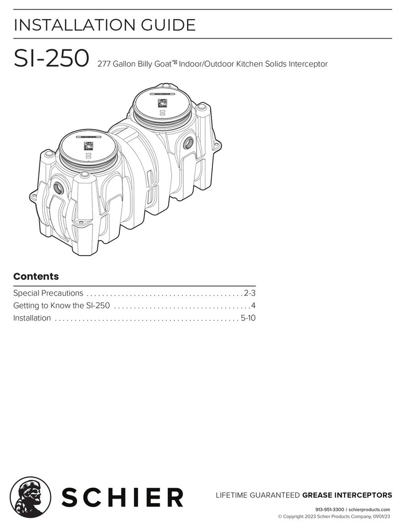
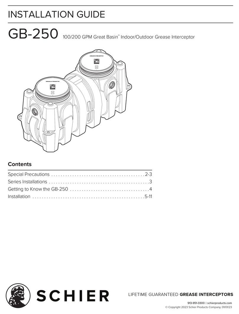
Schier GB-250 User manual

Schier

Schier GB-250 User manual

Schier GB3 User manual

Schier

Schier GB3 User manual

Schier GB2-CT User manual

Schier

Schier GB2-CT User manual

Schier PP3 User manual

Schier

Schier PP3 User manual

Schier GB-75 User manual

Schier

Schier GB-75 User manual

Schier GB2 User manual

Schier

Schier GB2 User manual

Schier GB-1000-L User manual

Schier

Schier GB-1000-L User manual

Schier GB1-CT User manual

Schier

Schier GB1-CT User manual

Schier GB2 User manual

Schier

Schier GB2 User manual

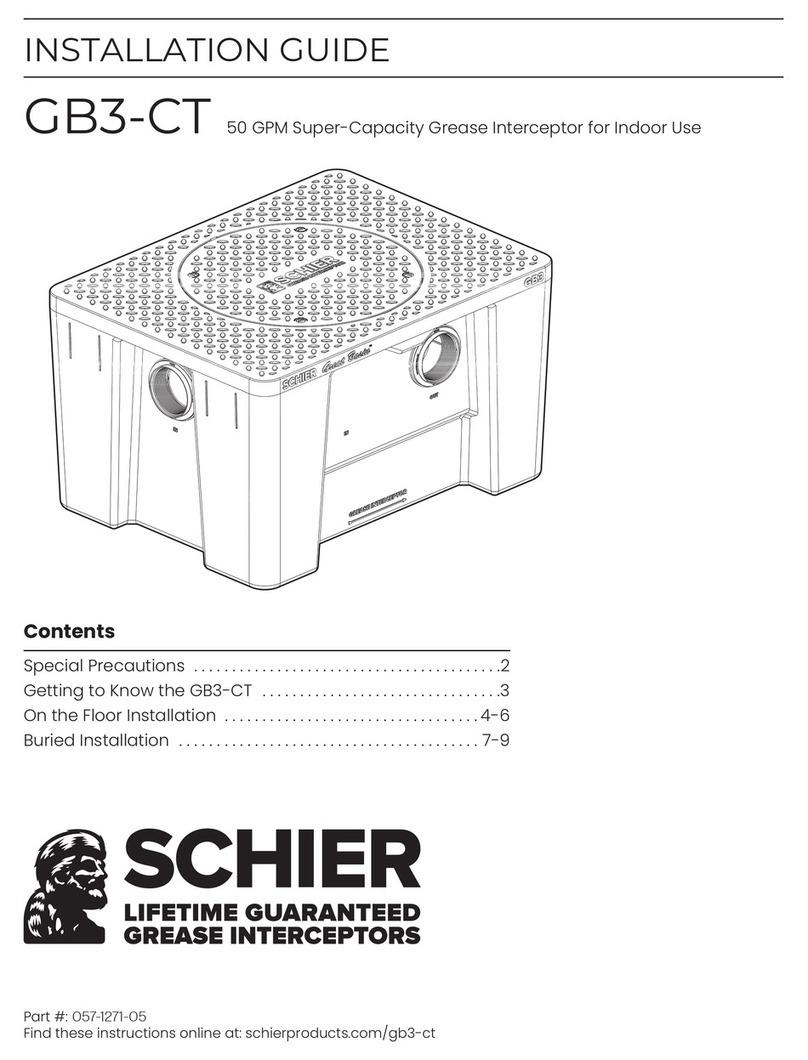
Schier GB3-CT User manual

Schier

Schier GB3-CT User manual

Schier SI-50 User manual

Schier

Schier SI-50 User manual

Schier GB-250-B User manual

Schier

Schier GB-250-B User manual

Schier GB-500 User manual

Schier

Schier GB-500 User manual

Schier SV10 User manual

Schier

Schier SV10 User manual

Schier SI-250 User manual

Schier

Schier SI-250 User manual
Schier GB-500-B User manual

Schier

Schier GB-500-B User manual

Schier PP3 User manual

Schier

Schier PP3 User manual

Schier GB-500-500HF User manual

Schier

Schier GB-500-500HF User manual

Schier GB-50 User manual

Schier

Schier GB-50 User manual

Schier SI-75 User manual

Schier

Schier SI-75 User manual
Schier GB-50 User manual

Schier

Schier GB-50 User manual

Schier GB-250 User manual

Schier

Schier GB-250 User manual

Schier FCR10 User manual

Schier

Schier FCR10 User manual

Schier GB-500-500HF User manual

Schier

Schier GB-500-500HF User manual

Popular Plumbing Product manuals by other brands

Moen rt4560 Specifications

Moen

Moen rt4560 Specifications

Haws 5010.6427SS Installation, operation & maintenance instructions

Haws

Haws 5010.6427SS Installation, operation & maintenance instructions

American Standard Heritage 6830.000 Specification sheet

American Standard

American Standard Heritage 6830.000 Specification sheet

Sloan Optima EBF-750 Repair Parts and Maintenance Guide

Sloan

Sloan Optima EBF-750 Repair Parts and Maintenance Guide

pure cube CU580D Assembly instructions

pure cube

pure cube CU580D Assembly instructions

IB RUBINETTERIE LoveMe LM250 Fitting instructions

IB RUBINETTERIE

IB RUBINETTERIE LoveMe LM250 Fitting instructions

JADO IQ 832 701 Series installation instructions

JADO

JADO IQ 832 701 Series installation instructions

Elkay LKB722C installation instructions

Elkay

Elkay LKB722C installation instructions

Grohe Grohtherm 24076000 manual

Grohe

Grohe Grohtherm 24076000 manual

AWT B1812A Installation and operation instruction

AWT

AWT B1812A Installation and operation instruction

Spectrum Brands Pfister Zuri GT-529-MP Quick installation guide

Spectrum Brands

Spectrum Brands Pfister Zuri GT-529-MP Quick installation guide

Karibu Sauna 280 Assembly instructions

Karibu

Karibu Sauna 280 Assembly instructions

Spectrum Brands Pfister Verve LG6-1VRV Quick installation guide

Spectrum Brands

Spectrum Brands Pfister Verve LG6-1VRV Quick installation guide

miseno MNOSA225CP manual

miseno

miseno MNOSA225CP manual

Pfister Vorena F534-7VO Quick installation guide

Pfister

Pfister Vorena F534-7VO Quick installation guide

Hans Grohe Zebris 110 CoolStart 72570 Series Instructions for use/assembly instructions

Hans Grohe

Hans Grohe Zebris 110 CoolStart 72570 Series Instructions for use/assembly instructions

Glacier bay GBSH114 instruction manual

Glacier bay

Glacier bay GBSH114 instruction manual

Tylo Tylosand T-820 Installation & user guide

Tylo

Tylo Tylosand T-820 Installation & user guide

manuals.online logo
manuals.online logoBrands
  • About & Mission
  • Contact us
  • Privacy Policy
  • Terms and Conditions

Copyright 2025 Manuals.Online. All Rights Reserved.