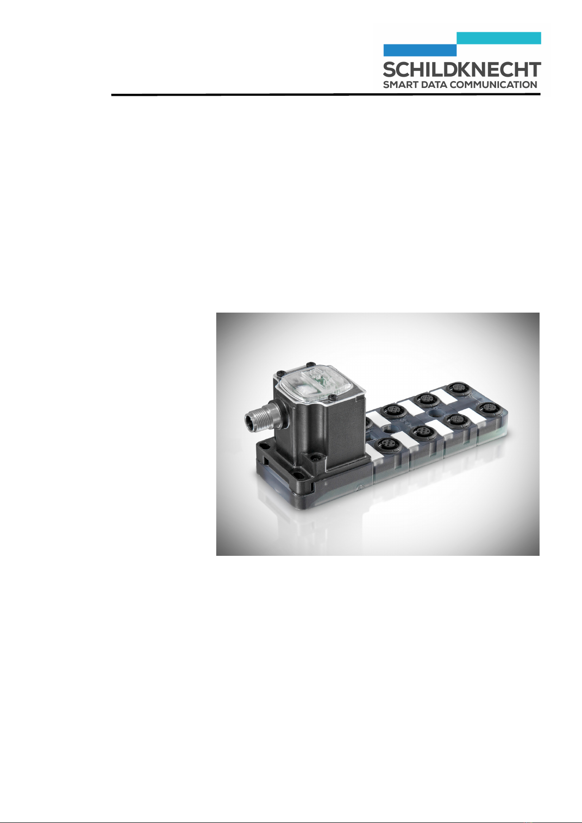
Installation and commissioning SET DATAEAGLE X-treme IO 2730
Chapter 1 – General information
1. General information
1.1. Guide to symbols
This section contains an explanation of the symbols used in
this manual.
Indicates an imminently hazardous situation which, if not
avoided, may result in death or serious injury.
Indicates a potentially hazardous situation which, if not
avoided, may result in property damage.
Indicates sections which contain important information.
Indicates work operations which need to be carried out.
This symbol is followed by a description about how the status
of the system changes after an operation has been carried
out.
1.2. Copyright and brand names
Brand names and product names mentioned in this manual
are trademarks or registered trademarks of their respective
owners.
Microsoft Windows 7, Windows Vista, Windows 2000, Win-
dows XP and Microsoft Internet Explorer are registered
trademarks of Microsoft Corp.
Adobe Reader is a registered trademark of Adobe Systems
Corp.
DATAEAGLE® is a registered trademark of Schildknecht AG.
1.3. Declaration of conformity and EC direc-
tives
Information about the declaration of conformity and about EC
directives can be found under:
http://www.schildknecht.ag/download/dataeagle-konformitaetserklaerung
CAUTION