©OMRON Corporation 2007-2008 All Rights Reserved.
CABLE EXTENSION UNIT
FOR MODEL FH, FZ AND FJ IMAGE SENSOR
Model FZ-VSJ
INSTRUCTION SHEET
Thank you for selecting OMRON product. This sheet pri-
marily describes precautions required in installing and
operating the product.
Before operating the product, read the sheet thoroughly to
acquire sufficient knowledge of the product. For your con-
venience, keep the sheet at your disposal.
●
●
PRECAUTIONS ON SAFETY
To ensure safety, do not use this product for direct or indirect detection
of data from human body. Do not use this product as a sensing device
for the protection of the human body.
WARNING
Indicates a potentially hazardous situation which, if not
avoided, may result in minor or moderate injury or in
property damage.
CAUTION
Indicates a potentially hazardous situation which, if not
avoided, will result in minor or moderate injury, or may
result in serious injury or death. Additionally there may
be significant property damage.
WARNING
■Accessory
■
2. Handling the FZ-VSJ
・Tighten all screws securely during installation.
・Tighten the camera connector by a regulated torque, 0.15N・m.
3.ExternalPowerSupplyandWiring
・The supply voltage must be within the rated range (DC11.5to13.5V).
・It is necessary to supply an external power supply by the direct current voltage
product designed so as not to generate a high voltage (safety extra low voltage
circuit).
・Reverse connection of the power supply is not allowed.
・Use the power supply within the rated load.
・High-voltage lines and power lines must be wired separately from this product.
Wiring them together or placing them in the same duct may cause induction,
resulting in malfunction or damage.
・For cables, do not use excluding the special cable. If might cause the malfunction or
damage.
4. Others
・Do not use unspecified camera other than those that specified in this manual with
the FZ controller.
Connection with unspecified camera cable and/or strobe controller may malfunction
at the worst case.
・Do not attempt to dismantle, repair, or modify the main unit.
・If you suspect an error or malfunction, stop using the controller immediately, turn
off the power supply, and consult your OMRON representative.
・D ispose of FZ-VSJ components as industrial waste.
5. Regulations and Standards
This product is compliant with the standards below:
EN Standards(European Standards), EN61326-1
Electromagnetic environment : Industrial electromagnetic environment
(EN/IEC 61326-1 Table 2)
Also, the following condition is applied to the immunity test of this product.
: If the level of disturbance of the video is that with
characters on the monitor are readable, the test is pass.
Observe the following precautions to prevent failure to operate, malfunctions, or
undesirable effects on product performance.
1. Connection and Wiring for Main Unit
・Confirm the connection of the main body before turning on controller's power
supply and external power supply. There is a possibility of the breakdown or
malfunction if the direction of the connection is mistaken.
・Be sure to turn off external power supply and controller before connecting or
disconnecting the cables.
2.External Power Supply and Wiring
・Before turning on the power after the product is connected, make sure that the
power supply voltage is correct, there are no incorrect connections(e.g.load
short-circuit)and the load current is appropriate. Incorrect wiring may result in
breakdown of the product.
3. External Power Supply Turning on
・Turn on controller's power supply after connecting an external power supply when
you use an external power supply.
・There is a possibility of malfunction if turning on controller's power supply earlier
than the external power supply.
4.Handling the Extension Unit
・The extension unit case is connected to the 0V line in the internalcircuits.
Observethe following precautions to prevent noise interference.
・Do not ground the extension unit.
・Do not remove the base attached to the extension unit.
5.Maintenance
・Do not use thinners, benzene, acetone, kerosene to clean the FZ-VSJ.
・Wipe off stubborn stains carefully with a piece of soft cloth that has been wetted
with a quantity of alcohol.
Main unit, Instruction sheet(this sheet), Mounting screw(M3×16mm)4pieces
Fix and use the main unit.
PRECAUTIONS FOR CORRECT USE
Specification
Item
Power supply Voltage Approx. 12VDC(11.5 to 13.5 VDC)
Output current 1.5 A min.
Recommended power supply Model S8VS-03012(12VDC, 2.5A)
Recommended electric wire size 16AWG to 22AWG(max. 5m)
■General Specifications
■Installation
150 m/s2, three times each in six directions
(up/down, left/right, forward/backward)
Operating and storage:35% to 85%
(with no condensation)
10 to 150 Hz, 0.35-mm single amplitude,
10 times each in X, Y, and Z directions for 8 min
Operating:0 to 50℃,
Storage:-25 to 60℃
(with no icing or condensation)
Must be free of corrosive gas.
Cover:Zinc-plated copper plate
Case side:Zinc-plated copper plate
Case:Zinc-plated copper plate
Mounting base:ABS
Approx. 240g(Including mounting base)
Model FZ-VSJ
Item
Shock resistance
Ambient temperature
Ambient humidity
Ambient environment
IEC60529, IP20
Degree of protection
Materials
Weight
Power consumption
Vibration resistance
1Wmax.(DC12V 0.09A max.)
Inputvoltagerangeof
externalpowersupply 11.5 to 13.5 VDC
Use a power supply that meets the following specifications.
Meaning of Alert Symbols
Alert statements
Observe the following precautions to ensure safe use of the Extension Unit.
1. Installation Site
Do not install this product in locations subjected to the following conditions.
・Ambient temperature outside the rating
・Rapid temperature fluctuations (causing condensation)
・Relative humidity outside the range of 35 to 85%
・Presence of corrosive, flammable gases, dust, salt, or iron particles
・Direct vibration or shock
・Reflection of intense light (such as other laser beams,
electric arc welding machines or ultraviolet rays)
・Direct sunlight or near heaters
・Water, oil, or chemical fumes or spray
・Strong magnetic or electric field
・Near high-voltage equipment or power equipment
PRECAUTIONS FOR SAFE USE
External Power Supply Connection
■
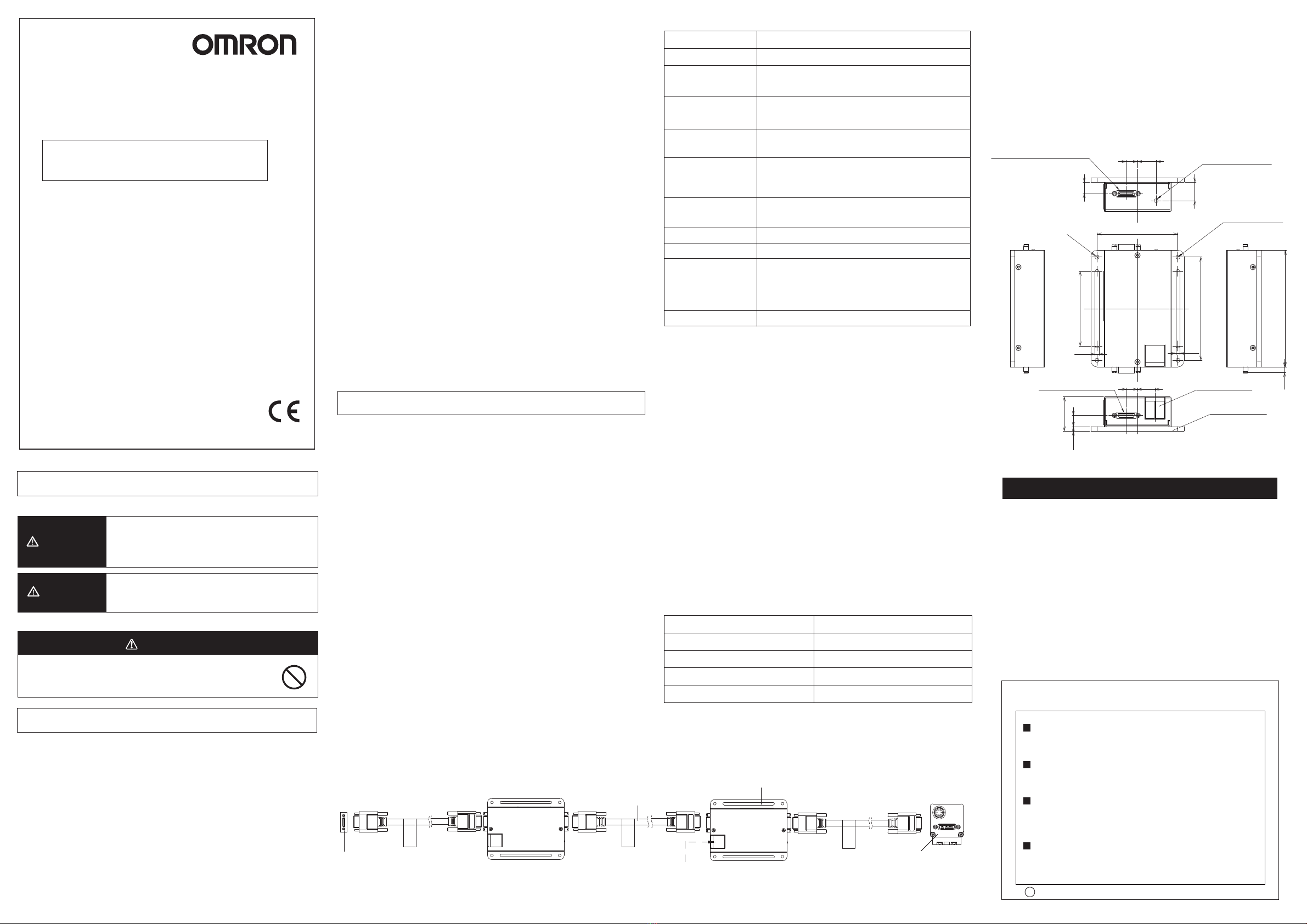
Dimensions
■External Power Supply Specification
1. Connect the power supply with the external power supply terminal as follows.
・In the controller FZ/FJ series:
When you connect the lighting by using the Cmaera-mount Lighting
Controller (FLV-TCC□/FL-TCC□/FZ-LTA□□□) and the strobe
control unit (MLEK-C100E1TS2) for camera (FZ-S□□□).
・In the controller Model FH series:
When you connect the lighting by using the Cmaera-mount Lighting
Controller (FLV-TCC□/FL-TCC) for camera (FZ-S□□□ and FH-S□□□).
・When FZ-SLC□□ is connected.
・When you connect the lighting with FZ-SZC□□□.
・When FZ-SQ□□□□ is connected.
2. Match the selection of the camera cable between the controller and the camera extension unit, the camera extension unit and the camera extension unit,
the camera extension unit and the camera to the camera of the connection.
Match the selection of the camera cable to the camera of the connection.
There is no problem even if the cable with a different length and kind is selected.
3. Turn on an external power supply before turning on the power supply to the
controller when you connect an external power supply.
Please turn off an external power supply after turning off controller's power supply
when you end.
2. Connect it by using crimping terminal (M3) according to the display of +/-
when you connect the cable with the external power supply terminal block.
4. Connect an external power supply with an extension unit that is the nearest the
camera when you connect the extension units of two units for each camera.
■Connection Method
※ThecameracableFZ-VS□□□seriesispolarized,so,makesurethattheend
bearinganameplateisconnectedtothecontrollerside.
CAMERA CABLE CONNECTOR
(CONTROLLER SIDE)
CABLE EXTENSION UNIT
FZ-VSJ
CAMERA
FZ-S□□□
FZ-SLC□□□
FZ-SZC□□□
FZ-SQ□□□□
FH-S□□□
EXTERNAL POWER SUPPLY
(Recommended power supply:
S8VS-03012)
CAMERA CABLE
FZ-VS□□
1. Cable extension unit FZ-VSJ can be connected up to two units for each camera.
3.Connect the controller with “CONTROLLER” display side.
■POWER LED LAMP
POWER LED shows that the cable extension unit works.
Even if the power supply is turned on to an external power supply it doesn't light.
Fix to the screw mounting hole of mounting base with attached mounting screw
(M3×16mm).
NOTICE:
This product meets CISPR11 class A. The intended use of this product is in an
industrial environment only.
Manufacturer:
Omron Corporation,
Shiokoji Horikawa, Shimogyo-ku,
Kyoto 600-8530 JAPA N
TRACEABILITY INFORMATION:
Importer in EU :
Omron Europe B.V.
Wegalaan 67-69
2132 JD Hoofddorp,
The Netherlands
(UNIT:mm)
83
65
60
3.2 3.2
149
9.1
27.5
4
CAMERA CABLE
CONNECTOR
(CONTROLLER SIDE) POWER TERMINAL
159
9.1
14.9
CAMERA CABLE CONNECTOR
(CAMERA SIDE)
POWER LED INDICATOR
SCREW MOUNTING
HOLE
93.8
4.65
4-3.4 Dia
MOUNTING BASE
Suitability for Use
s
Omron Companies shall not be responsible for conformity with any standards,
codes or regulations which apply to the combination of the Product in the
Buyer’s application or use of the Product. At Buyer’s request, Omron will
provide applicable third party certification documents identifying ratings and
limitations of use which apply to the Product. This information by itself is not
sufficient for a complete determination of the suitability of the Product in
combination with the end product, machine, system, or other application or
use. Buyer shall be solely responsible for determining appropriateness of the
particular Product with respect to Buyer’s application, product or system.
Buyer shall take application responsibility in all cases.
NEVER USE THE PRODUCT FOR AN APPLICATION INVOLVING
SERIOUS RISK TO LIFE OR PROPERTY WITHOUT ENSURING THAT THE
SYSTEM AS A WHOLE HAS BEEN DESIGNED TO ADDRESS THE RISKS,
AND THAT THE OMRON PRODUCT(S) IS PROPERLY RATED AND
INSTALLED FOR THE INTENDED USE WITHIN THE OVERALL
EQUIPMENT OR SYSTEM.
See also Product catalog for Warranty and Limitation of Liability.
Oct, 2014
D
OMRON Corporation Industrial Automation Company
Contact: www.ia.omron.com
Tokyo, JAPAN
OMRON ELECTRONICS LLC
2895 Greenspoint Parkway, Suite 200
Hoffman Estates, IL 60169 U.S.A.
Tel: (1) 847-843-7900/Fax: (1) 847-843-7787
OMRON ASIA PACIFIC PTE. LTD.
No. 438A Alexandra Road # 05-05/08 (Lobby 2),
Alexandra Technopark,
Singapore 119967
Tel: (65) 6835-3011/Fax: (65) 6835-2711
OMRON (CHINA) CO., LTD.
Room 2211, Bank of China Tower,
200 Yin Cheng Zhong Road,
PuDong New Area, Shanghai, 200120, China
Tel: (86) 21-5037-2222/Fax: (86) 21-5037-2200
OMRON EUROPE B.V.
Sensor Business Unit
Carl-Benz-Str. 4, D-71154 Nufringen, Germany
Tel: (49) 7032-811-0/Fax: (49) 7032-811-199
Regional Headquarters


V2 User manual")


