manuals.online logo
Brands
  1. Home
  2. •
  3. Brands
  4. •
  5. ipf electronic
  6. •
  7. Accessories
  8. •
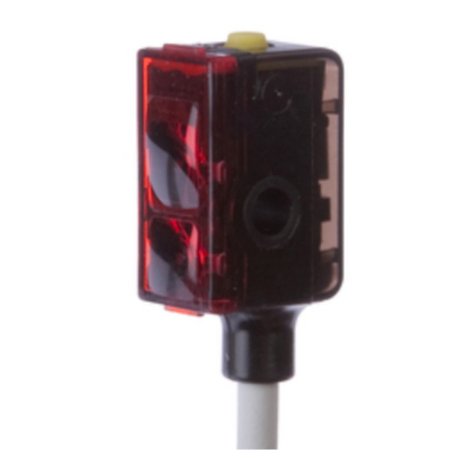
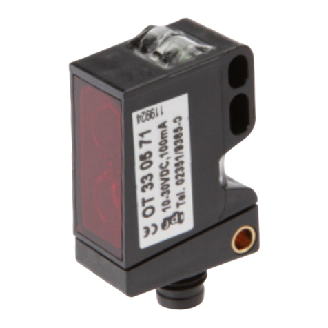
  9. ipf electronic ON430571 User manual

ipf electronic ON430571 User manual

operating distance 800mm
robust plastic housing, compact design
for detecting transparent objects
Teach in-based setting
LED display for fine adjustment
reduction in the level of reciprocal optical interference
connection with 4-pin M8-connector
Technica datal
version transparent objects recognition (trays / bottles)
background position (Sde) 200 … 800mm on shiny metallic surfaces
detection range (Sa) 100% of Sde
operating voltage UB 10 … 30V DC
current consumption (w/o load) ≤ 35mA
output current (max. load) ≤ 100mA
output signal push-pull, no/nc
voltage drop (max. load) ≤ 2V DC
reaction- /decay time ≤ 1.8msec
sampling frequency ≤ 270Hz
short-circut protection +
reverse polarity protection +
display (signal) green LED
display (status) / setting control red LED
transmitting element red LED, 660nm, pulsed
light spot size
housing material
front screen material
system of protection
Ø15mm at 800mm
plastic (ASA-MABS)
PMMA
IP67 (EN 60529)
operating temperature -30°C … +60°C
connection
max. tightening torque
M8-connector, 4-pin
0.8Nm
description:
These completely new through-beam sensors work according to the principle established with the retro-reflective
sensor. With these devices however, no retro-reflector is used. Any flat surface can be used as a reflector, e.g. the wall
of a piece of machinery.
This is `teached in' as a background item, via the Teach-In line (white wire, PIN 2). Each object that is located between
the sensor and background position is detected. This induces a change to the signal at the switch output. The system
also detects transparent objects. The position and characteristics of the background should not change whilst the
device is in operation. In the case of metallic shiny surfaces, the maximum ran-ge is 800mm. In the case of other
materials, the operating distance is reduced!
new: works like a retro-reflective
sensor - but without a reflector
ON430571
MANUAL •Subject to alteration! Version: May 2016
ipf electronic gmbh
•Rosmarter Allee 14 •58762 Altena
│
Tel +49 2351 9365-0 •Fax +49 2351 9365-19
│
[email protected] •www.ipf-electronic.com 1
the teach-in procedure relating to through-beam sensor operation:
1. Align the sensor towards a reflective part of the machinery.
2. Connect the Teach-In line (white, PIN 2) for longer than 2 seconds (however less than 5 seconds) with +UB. The red LED will
flash.
3. Connect the Teach-In line again for a short period with +UB.
4. If the sensor is intended to work as a break contact (output switched if an object is detected), then connect the Teach-In
line again for a short period with +UB. Otherwise the device works as a make contact.
5. In the case of soiling and temperature effects, the switching threshold is only corrected if the path of light to the re-flecting
machinery part is free from obstructions.
notes: The above status information applies to a „plus switching“ (pnp) connection. For a „minus switching“ (npn)
connection the status information has to be inverted.
In the teach mode, the output changes over to 0V.
Under normal operations, the Teach-In line must be grounded (0V)!
If the sensor is `teached in' outside of its detection range, or if the quality of the signal is insufficient, a warning signal
will be displayed (rapid flashing of the red LED). The sensor will then retain its previous setting.
If there is a short circuit at the switching output, the red LED will flash approx. once a second.
alignment mark
Connect the teach-line to +UB for more than 10 seconds. The red LED flashes rapidly.
Break the connection. If the red LED light now goes out, this means that the signal quality is insufficient, or the sensor is outside the
detection range. No teach in is possible. In the case of a flashing LED, the signal quality is good. The sensor can now be teached.
In order to return to the normal mode, connect the Teach-In line for a short period to +UB.
electric connection dimension drawing
suitable cable socket: e.g. VK200375
Warning: Never use these devices in applications where the safety of a person depends on their
functionality.
* transmitter axis
wire colors: bn = brown (1), wh = white (2), bu = blue (4), bk =
black (4)
Teach-in-input
switching output
MANUAL •Subject to alteration! Version: May 2016
ipf electronic gmbh
•Rosmarter Allee 14 •58762 Altena
│
Tel +49 2351 9365-0 •Fax +49 2351 9365-19
│
[email protected] •www.ipf-electronic.com 2

Other ipf electronic Accessories manuals
ipf electronic OTR49175 User manual

ipf electronic

ipf electronic OTR49175 User manual

ipf electronic UT189020 User manual

ipf electronic

ipf electronic UT189020 User manual

ipf electronic OTQ80576 User manual

ipf electronic

ipf electronic OTQ80576 User manual
ipf electronic PT65 Series User manual

ipf electronic

ipf electronic PT65 Series User manual

ipf electronic OTR49176 User manual

ipf electronic

ipf electronic OTR49176 User manual

ipf electronic DW34311 Series User manual

ipf electronic

ipf electronic DW34311 Series User manual

ipf electronic OT450521 User manual

ipf electronic

ipf electronic OT450521 User manual

ipf electronic UT129023 User manual

ipf electronic

ipf electronic UT129023 User manual

ipf electronic RO570900 User manual

ipf electronic

ipf electronic RO570900 User manual

ipf electronic OT05E244 User manual

ipf electronic

ipf electronic OT05E244 User manual

ipf electronic UT300025 User manual

ipf electronic

ipf electronic UT300025 User manual

ipf electronic OT05E287 User manual

ipf electronic

ipf electronic OT05E287 User manual

ipf electronic OTR49174 User manual

ipf electronic

ipf electronic OTR49174 User manual

ipf electronic UT129521 User manual

ipf electronic

ipf electronic UT129521 User manual

ipf electronic UT30C310 User manual

ipf electronic

ipf electronic UT30C310 User manual

ipf electronic UT139570 User manual

ipf electronic

ipf electronic UT139570 User manual

ipf electronic MW10015 Series User manual

ipf electronic

ipf electronic MW10015 Series User manual

ipf electronic UT360321 User manual

ipf electronic

ipf electronic UT360321 User manual

ipf electronic OT330571 User manual

ipf electronic

ipf electronic OT330571 User manual

ipf electronic UT309023 User manual

ipf electronic

ipf electronic UT309023 User manual
ipf electronic UT300027 User manual

ipf electronic

ipf electronic UT300027 User manual

ipf electronic OTQ90170 User manual

ipf electronic

ipf electronic OTQ90170 User manual
ipf electronic DW35312 Series User manual

ipf electronic

ipf electronic DW35312 Series User manual

ipf electronic UT36002B User manual

ipf electronic

ipf electronic UT36002B User manual

Popular Accessories manuals by other brands

Syride SYS'One V3 user manual

Syride

Syride SYS'One V3 user manual

Hettich HettCube 200 operating manual

Hettich

Hettich HettCube 200 operating manual

SICK LMS4000 operating instructions

SICK

SICK LMS4000 operating instructions

Valore PB01 user manual

Valore

Valore PB01 user manual

Snom M900 Provisioning guide

Snom

Snom M900 Provisioning guide

Tektronix P6249 instruction manual

Tektronix

Tektronix P6249 instruction manual

TIS MS-PIR-M installation manual

TIS

TIS MS-PIR-M installation manual

Land Pride 318-586A Operator's manual

Land Pride

Land Pride 318-586A Operator's manual

Cognex DS1000 Series Reference

Cognex

Cognex DS1000 Series Reference

Fiamma F1L Repair instructions

Fiamma

Fiamma F1L Repair instructions

Multibrackets 7350073739622 installation manual

Multibrackets

Multibrackets 7350073739622 installation manual

Sony XC-ST50 Specifications

Sony

Sony XC-ST50 Specifications

Soundmachines (arches) owner's manual

Soundmachines

Soundmachines (arches) owner's manual

Aduance U3GLAN3HUB user guide

Aduance

Aduance U3GLAN3HUB user guide

Sigfox WSSFCB-NH3 user guide

Sigfox

Sigfox WSSFCB-NH3 user guide

Axis T8342 user manual

Axis

Axis T8342 user manual

Pavone Systems DAT 100 Technical manual

Pavone Systems

Pavone Systems DAT 100 Technical manual

PCB Piezotronics 137B24B Installation and operating manual

PCB Piezotronics

PCB Piezotronics 137B24B Installation and operating manual

manuals.online logo
manuals.online logoBrands
  • About & Mission
  • Contact us
  • Privacy Policy
  • Terms and Conditions

Copyright 2025 Manuals.Online. All Rights Reserved.