APG LPU-2127 User manual

APG
R
Doc #9002657
Rev B, 01/15
LPU-2127
User Manual

ii Tel: 1/888/525-7300 • Fax: 1/435/753-7490 • www.apgsensors.com • [email protected]
Table of Contents
Introduction ................................................................................................................ iii
Warranty and Warranty Restrictions.................................................................... iv
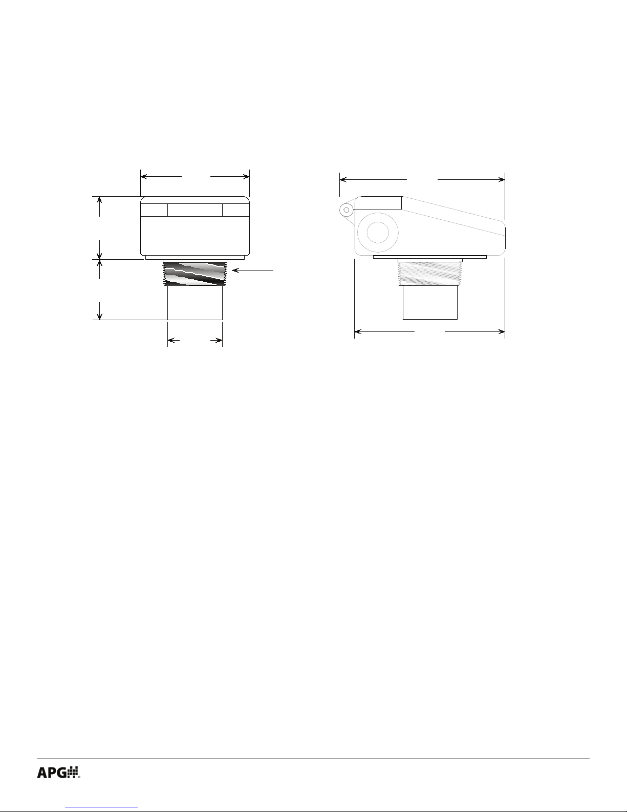
Chapter 1: Specications and Options..................................................................... 1
Dimensions ........................................................................................................................................1
Specications ................................................................................................................................... 2
Chapter 2: Installation and Removal Procedures and Notes..............................3
Tools Needed..................................................................................................................................... 3
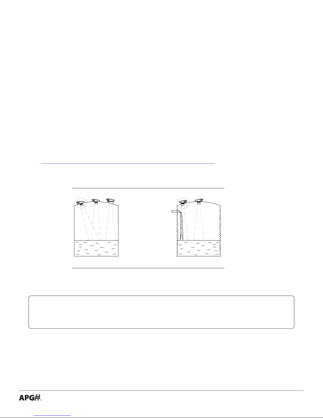
Installation Notes ............................................................................................................................ 3
Mounting Instructions ................................................................................................................... 4
Electrical Installation ..................................................................................................................... 4
Removal Instructions ..................................................................................................................... 4
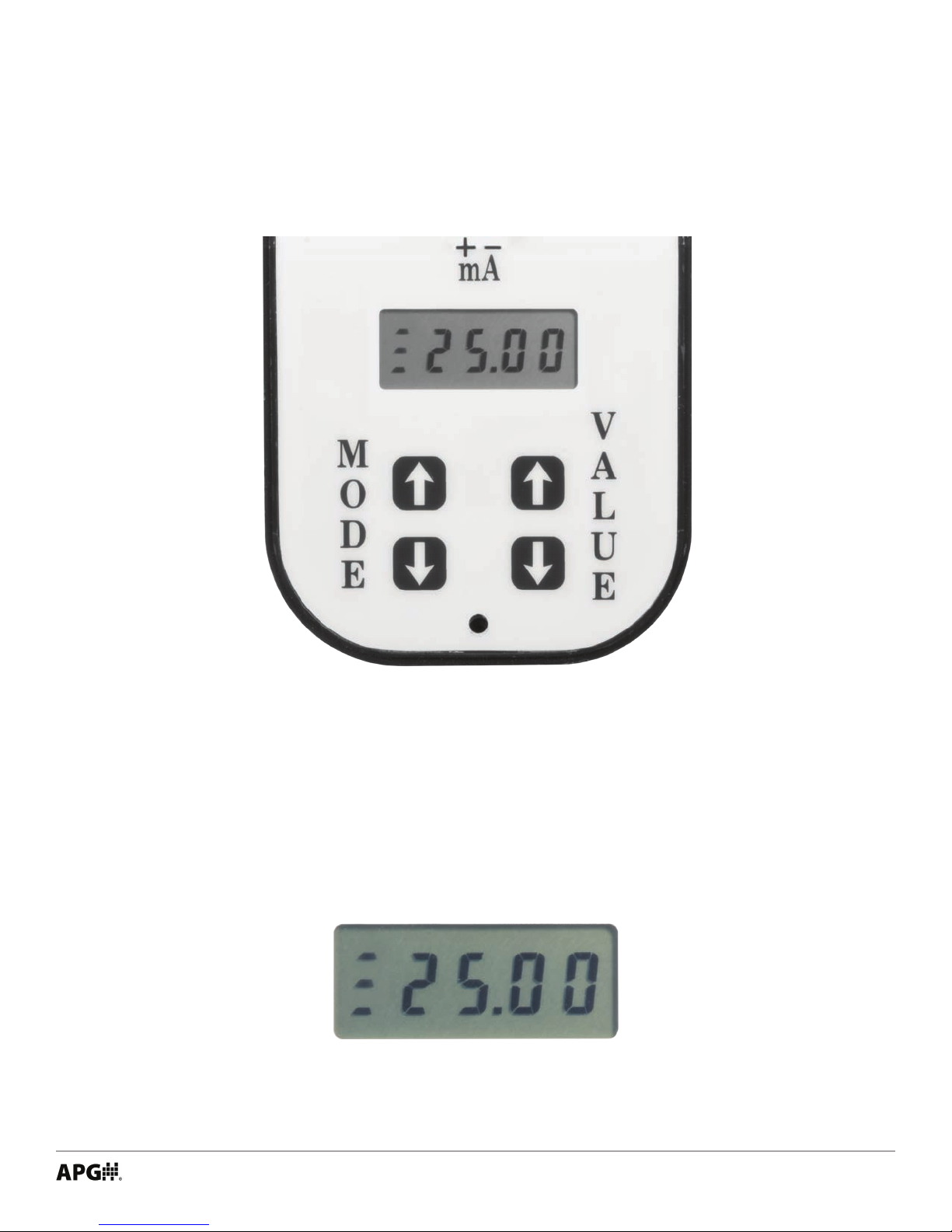
Chapter 3: Set Up and Operation ..............................................................................4
User Interface ............................................................................................................................... 4-5
Operation Modes .......................................................................................................................... 6-7
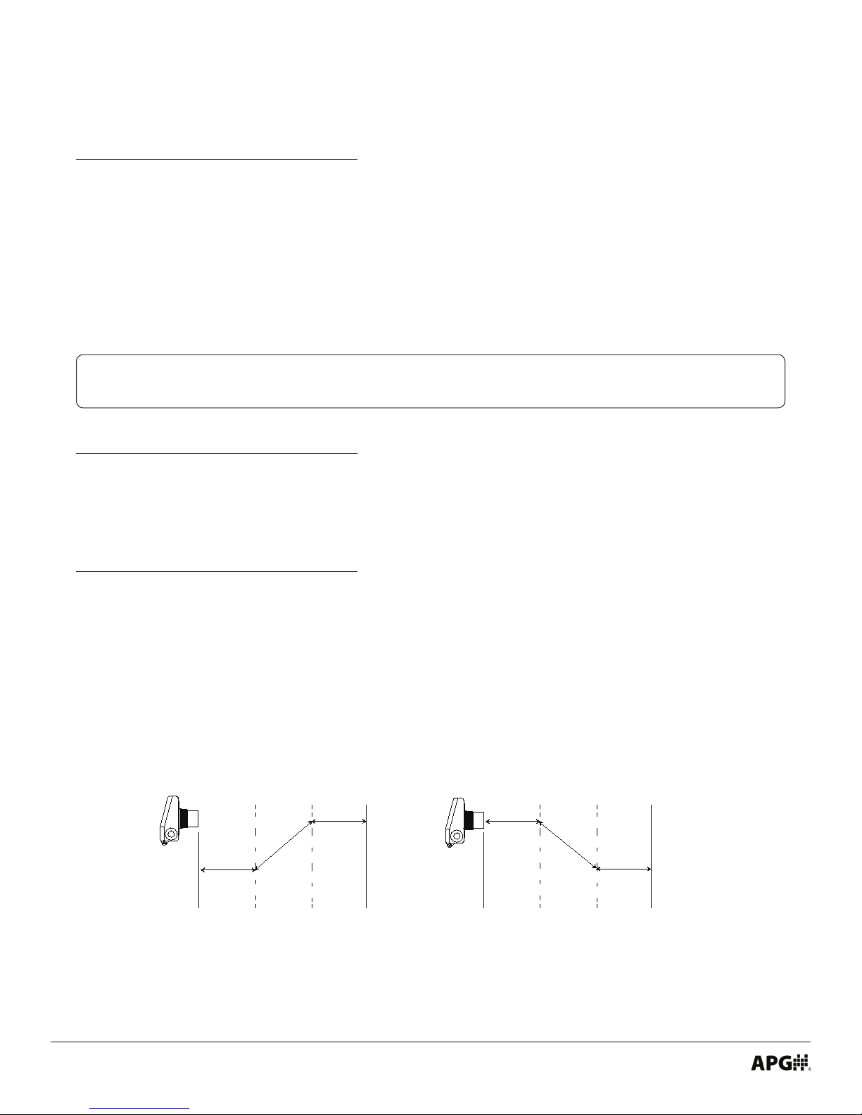
Calibration Modes.........................................................................................................................7-8
Utility Modes ................................................................................................................................ 8-9
Chapter 4: Maintenance .............................................................................................9
General Care...................................................................................................................................... 9
Troubleshooting............................................................................................................................. 10
Calibration ....................................................................................................................................... 10
Repair and Returns.........................................................................................................................11
Chapter 5: Hazardous Location Drawing and Certication .............................. 12
Hazardous Location Drawing ...................................................................................................... 12
CSA Certicate of Compliance...............................................................................................13-16

iii
Introduction
Thank you for purchasing a LPU-2127 ultrasonic sensor from APG. We appreciate your business! Please take
a few minutes to familiarize yourself with your LPU-2127 and this manual.
The LPU-2127 loop-powered ultrasonic sensor provides a low-power, non-contact level measurement
solution rated for hazardous locations and suitable for harsh chemical environments. It oers a built-in
keypad and four digit LCD display for easy setup, and a NEMA 4X cover for outdoor applications.
Reading your label
Every APG instrument comes with a label that includes the instrument’s model number, part number, serial
number, and a wiring pinout table. Please ensure that the part number and pinout table on your label
match your order. The following electrical ratings and approvals are also listed on the label. Please refer to
the Certicate of Compliance at the back of this manual for further details.
Electrical ratings
Input: 12 to 28 Volts DC; Output: 4-20mA
Class I Division 2; Groups C, D T6
Class I, Zone 2, Group IIB
AEx nA IIB T6: Ta: -40°C to 60°C; IP65
Ex nA IIB T6: Ta: -40°C to 60°C; IP65
IMPORTANT: The LPU-2127 must be installed as shown on drawing 9002745 to meet
listed approvals. Faulty installation will invalidate all safety approvals and ratings.

iv Tel: 1/888/525-7300 • Fax: 1/435/753-7490 • www.apgsensors.com • [email protected]
Warranty and Warranty Restrictions
APG warrants its products to be free from defects of material and workmanship and will, without charge,
replace or repair any equipment found defective upon inspection at its factory, provided the equipment has
been returned, transportation prepaid, within 24 months from date of shipment from factory.
THE FOREGOING WARRANTY IS IN LIEU OF AND EXCLUDES ALL OTHER WARRANTIES NOT EXPRESSLY SET
FORTH HEREIN, WHETHER EXPRESSED OR IMPLIED BY OPERATION OF LAW OR OTHERWISE INCLUDING
BUT NOT LIMITED TO ANY IMPLIED WARRANTIES OF MERCHANTABILITY OR FITNESS FOR A PARTICULAR
PURPOSE.
No representation or warranty, express or implied, made by any sales representative, distributor, or other
agent or representative of APG which is not specically set forth herein shall be binding upon APG. APG shall
not be liable for any incidental or consequential damages, losses or expenses directly or indirectly arising
from the sale, handling, improper application or use of the goods or from any other cause relating thereto
and APG’s liability hereunder, in any case, is expressly limited to the repair or replacement (at APG’s option)
of goods.
Warranty is specically at the factory. Any on site service will be provided at the sole expense of the
Purchaser at standard eld service rates.
All associated equipment must be protected by properly rated electronic/electrical protection devices. APG
shall not be liable for any damage due to improper engineering or installation by the Purchaser or third
parties. Proper installation, operation and maintenance of the product becomes the responsibility of the
user upon receipt of the product.
Returns and allowances must be authorized by APG in advance. APG will assign a Return Material
Authorization (RMA) number which must appear on all related papers and the outside of the shipping
carton. All returns are subject to the nal review by APG. Returns are subject to restocking charges as
determined by APG’s “Credit Return Policy”.

1
Chapter 1: Specications and Options
• Dimensions
4.00"
101.6 mm
5.50"
139.7 mm
6.05"
153.7 mm
2.00"
50.80 mm
2.40"
60.96 mm
2.30"
58.42 mm
2" NPT

2Tel: 1/888/525-7300 • Fax: 1/435/753-7490 • www.apgsensors.com • [email protected]
Performance
Operating Range 1 - 25 ft. (0.3 - 7.6 m) on liquids and hard, at surfaces
1 - 10 ft. (0.3 - 3 m) on bulk solids
Analog Output 4-20 mA
Beam Pattern 9° o axis
Frequency 69 kHz
Response Time 0.6 - 3 seconds (dependent on output range)
Sample Rate 3 seconds @ 4 mA
0.6 seconds @ 20 mA
Accuracy
Accuracy ±0.25% of detected range
Resolution 0.1 inch (2.54 mm)
Environmental
Operating Temperature -40 to 60°C (-40 to 140°F)
Internal Temperature Compensation Yes
Enclosure Protection IP65
NEMA rating 4X
Electrical
Supply Voltage (at sensor) 12-28 VDC
Current Draw 22 mA max
Output Signal 3-30 mA max
Load Resistence 150Ω max @ 12 VDC
600Ω max @ 24 VDC
Cable Connection 2-terminal connector
Masterials of Construction
Transducer Housing PVDF (Kynar®)
Upper Housing PET
• Specications

3
Chapter 2: Installation and Removal Procedures and Notes
Tools are not necessary for installing the LPU itself. If you are using a stand pipe to mount your LPU, you will
probably need tools to install the stand pipe, but not for the LPU.
• Tools Needed
• Installation Notes
• Mount your LPU sensor so that it has a clear, perpendicular sound path to the surface being moni-
tored. Your sensor should be mounted away from tank or vessel walls and inlets. See Figure 2.1.
• The sound path should be free from obstructions and as open as possible for the 9° o axis beam
pattern.
• If you are using a stand pipe, please see our guide to stand pipes on our website:
http://www.apgsensors.com/about-us/blog/how-to-install-a-stand-pipe.
Figure 2.1
NOTE: Do not mount the sensor where the beam will intersect objects such as ll
streams, pipes, ladder rungs, wall seams, or corrugated tank walls.

4Tel: 1/888/525-7300 • Fax: 1/435/753-7490 • www.apgsensors.com • [email protected]
• Mounting Instructions
• With the lid of your LPU closed, remove the cable knock out.
• Clear the ashing.
• Open the lid of your LPU and intall cable gland or conduit connection.
• Connect 12-28 VDC supply wire to (+) Terminal
• Connect 4-20 mA output wire to (-) Terminal.
• Electrical Installation
• Remove the sensor and store it in a dry place, at a temperature between -40° F and 180° F.
• Removal Instructions
Mounting your LPU is easy if you follow a few simple steps:
• Never over-tighten the sensor.
• Always screw in your sensor by hand to avoid cross-threading. Thread failure can be a problem if you
damage threads by over-tightening them or by crossing threads.
IMPORTANT: Do not over tighten! The sensor should be threaded in only hand tight.
The LPU display and programming buttons can be accessed by loosening the screw that secures and seals
the sensor’s lid. The LCD display shows the distance measurement. The display is also used to view the
individual modes and their values when programming.
The LPU controls operate similar to a digital wrist watch. The LPU has four buttons, MODE UP, MODE
DOWN, VALUE UP, and VALUE DOWN (See Figure 3.1). The MODE UP/DN buttons allow the user to select the
desired mode while VALUE UP/DN buttons allow the user to view and alter the settings.
To select a mode, press the MODE UP or MODE DOWN button until the desired mode is displayed. Press the
VALUE UP or VALUE DOWN button once to view the current setting of that mode.
To change the selected mode setting, press the VALUE UP or VALUE DOWN button until the desired value is
displayed.
Chapter 3: Set Up and Operation
• User Interface

5
Figure 3.1
Along with the buttons and the display, the LPU-2127 includes a detected signal strength indicator. On the
leftside of the display are bars to indicate the strength of the signal returning to the sensor (See Figure 3.2).
Three bars indicates excellent signal strength; two bars indicates good signal strength; one bar indicates fair
signal strength; no bars indicates loss of echo (no signal).
Figure 3.2
To STORE or SAVE the changed mode value, press the MODE UP or MODE DOWN button once. At this point,
the display will show the distance measurement. The values are stored in a nonvolatile memory, and will not
be lost when power is turned o.

6Tel: 1/888/525-7300 • Fax: 1/435/753-7490 • www.apgsensors.com • [email protected]
• Operation Modes
MODE DESCRIPTION PARAMETERS
1 Units Range = 0-2
Default = 0
0 = feet
1 = inches
2 = mm
Mode 1 is used to select the units of measurement that will be used throughout the setup process and also
for display. The units will also determine the resolution of the display and the outputs. The resolution is: feet
0.01, inches 0.1, and millimeters 1.
NOTE: All modes must be set using the units selected in Mode 1.
MODE DESCRIPTION PARAMETERS
2 4 mA distance Units = Mode 1
Range = 0-9999
Default = 1.00 ft.
Mode 2 sets the 4 mA distance, measured from the Zero Point (See mode 10).
MODE DESCRIPTION PARAMETERS
3 20 mA distance Units = Mode 1
Range = 0-9999
Default = 25.00 ft.
Mode 3 sets the 20 mA distance, measured from the Zero Point (See mode 10).
For Distance conguration (i.e., greater mA output for target surface further from sensor), set the mode 2
distance to be less than the mode 3 distance (See Figure 3.3).
For Fill conguration (i.e., greater mA output for target surface closer to sensor), set the mode 2 distance to
be greater than the mode 3 distance (See Figure 3.4).
Zero Point Max. Distance Zero Point Max. Distance
mode 2 mode 3 mode 3 mode 2
20 ma
4 ma
20 ma
4 ma
Figure 3.3 Figure 3.4

7
MODE DESCRIPTION PARAMETERS
4 Response Time Range = 1-3
Default = 1
1 = 3.3 ft/min (1m/min)
2 = 15ft/min (4.5m/min)
3 = >15 ft/min (4.5/min)
Mode 4 is used to select the desired response time of the sensor. The response time represents the
maximum rate of change in target level that the sensor will accurately display. Thus, setting 1 (3.3 ft/min) is
the slowest setting, and setting 3 ( >15 ft/min) is the fastest.
MODE DESCRIPTION PARAMETERS
5 Fail-safe Range = 0 - 2
Default = 1
0 = hold last
1 = 22 mA
2 = 3.75 mA
Mode 5 sets the output condition that the sensor will revert to in the event of a loss of echo condition. If this
mode is set to 0, the sensor will hold the last reading until the signal is regained. If set to 1, the output of the
sensor will go to 22 mA. If set to 2, the output will go to 3.75 mA.
MODE DESCRIPTION PARAMETERS
6 Fail-safe Units = Seconds
Delay Range = 5-9999
Default = 15
Mode 6 sets the delay, in seconds, before the output will show a loss of echo condition set in Mode 5. When
this time has expired, the display and output will change to their fail-safe settings.
• Calibration Modes
MODE DESCRIPTION PARAMETERS
7 4 mA Trim Range = 0-9999
Default = 5000
Mode 7 ne tunes the minimum current sourced on the analog output.
MODE DESCRIPTION PARAMETERS
8 20 mA Trim Range = 0-9999
Default = 5000
Mode 8 ne tunes the maximum current sourced on the analog output.
MODE DESCRIPTION PARAMETERS
9 Calibration Range = 0-1999
Default = 1000
Mode 9 is used to calibrate the sensor for variations in the speed of sound due to variations in atmospheres.
The default of 1000 is used for most applications. Assume a decimal after the rst digit.
NOTE: Most applications do not require the user to manipulate modes beyond 6.

8Tel: 1/888/525-7300 • Fax: 1/435/753-7490 • www.apgsensors.com • [email protected]
• Utility Modes
MODE DESCRIPTION PARAMETERS
11 Temperature Range = 0 - 2
Compensation Default = 1
0 = OFF
1 = ON
2 = View Temperature (degrees C)/ON
Mode 11 activates or deactivates the internal temperature compensation circuit. The speed of sound
changes with changes in temperature, therefore changes in temperature can aect distance measurements.
These aects can be minimized by activating temperature compensation. If the mode is exited while
viewing temperature, temperature compensation is turned ON.
MODE DESCRIPTION PARAMETERS
12 AutoSense Range = 0 - 1
Default = 1
0 = Manual (user controls Sensitivity and Pulses)
1 = AutoSense (sensor controls Sensitivity and Pulses)
Mode 12 activates or deactivates AutoSense. When operating with this mode active, the LPU-2127 will
automatically change the sensitivity and pulses to match the application. Modes 13 and 15 limit the
maximum level that sensitivity and pulses can be manipulated when operating in AutoSense. Modes 13 and
15 set the sensitivity and pulses when operating in manual mode.
MODE DESCRIPTION PARAMETERS
13 Sensitivity Range = 0 - 100%
Default = 100%
Mode 13 sets the level of gain that is applied to the echo. When operating in AutoSense, this parameter
limits the gain that can be applied to the echo. If operating in manual, this parameter sets the receive gain.
When in manual mode, set the sensitivity to the minimum value that will allow the target to be reliably
tracked through the full range of expected environmental conditions.
MODE DESCRIPTION PARAMETERS
10 Distance Oset Units = Mode 1
Range = -3.00 to 3.00
Default = 0
Mode 10 is used to change the Zero Point of the sensor. This not the zero output (4 mA) point of the sensor.
The Zero Point of the sensor is the point from which the calculated distance is measured. See Figures 3.3
and 3.4 on page 6.

9
Your LPU-2127 ultrasonic sensor is very low maintenance and will need little care as long as it was installed
correctly. However, in general, you should:
• Avoid applications for which the sensor was not designed, such as extreme temperatures, contact with
incompatible corrosive chemicals, or other damaging environments.
• Inspect the threads whenever you remove the sensor from duty or change its location.
Chapter 4: Maintenance
• General Care
MODE DESCRIPTION PARAMETERS
14 Blanking Units = Determined by Mode 1
Range = 0.5 -16 ft.
Default = 1.00 ft.
Mode 14 sets the Blanking distance, which is the zone from the sensor to a point where the rst echo will
be accepted. While blanking distance can be used to ignore unwanted targets -- such as welds, seams, pipe
ttings, or gaskets -- between the sensor and the closest acceptable target level, such objects generally
create additional reections and echoes, which are hard to lter out. More often, Blanking distance is used
for a sensor installed in a stand pipe.
Because of the physical properties of an ultrasonic sensor, objects cannot be detected closer than
approximately 1 foot from the face of the transducer. However, this distance varies according to how much
energy is being transmitted (Mode 15) and the installation. Low pulses and soft mounting may allow target
detection as close as 6 inches.
MODE DESCRIPTION PARAMETERS
15 Pulses Range = 1-20
Default = 16
Mode 15 sets the maximum number of pulses the sensor can transmit when operating in AutoSense or
simply the number of pulses when operating in Manual (mode 12). The LPU emits a burst of pulses and
measures the time it takes for the burst to travel to and from the target. The more pulses that are sent in a
burst, the stronger the returning echo. When operating in Manual, increase the strength of the transmission
by increasing the number of pulses for detecting soft targets in damping environments. In acoustically active
environments or small enclosed areas, decrease the number of pulses to reduce multiple echoes.
MODE DESCRIPTION
16 Software Version
Mode 16 displays the software version of the LPU.
MODE DESCRIPTION
17 Reset
Mode 17 resets the LPU to factory default settings.

10 Tel: 1/888/525-7300 • Fax: 1/435/753-7490 • www.apgsensors.com • [email protected]
measure
measure
This procedure uses targets at known distances to calibrate the sensor’s accuracy. A wall or other large, at
object is recommended for the long range target.
• Point the sensor at a target at a known distance near the maximum range of the sensor, 25’ for a single
solid object (See Figure 4.1).
• Adjust the Calibration value (mode 9) until the distance reading on the sensor matches the actual mea-
sured distance to the target.
• Point the sensor at a target near the minimum measurement range, 1’ plus any Blanking distance (See
Figure 4.2).
• Adjust the Distance Oset value (mode 10) until the distance reading on the sensor matches the actual
measured distance to the target.
• Repeat previous two steps until no further adjustment is required.
• Calibration
NOTE: Mode 17 will reset the LPU to factory default settings.
Figure 4.1 Figure 4.2
Should you have problems with your LPU-2127, here are some troubleshooting steps.
• Check the received signal strength (See Figure 3.2 on page 5). If the signal strength is low, alternately
increase Pulses (mode 15) and Sensitivity (mode 13) until the signal strength improves.
• Ensure Temperature Compensation (mode 11) is turned on.
• Ensure AutoSense (mode 12) is turned on.
• Ensure that Blanking (mode 14) is accurately set to account for any unwanted targets between the sen-
sor and the closest acceptable target.
• Trouble Shooting

11
Should your LPU-2127 ultrasonic sensor require service, please contact the factory via phone, email, or
online chat. We will issue you a Return Material Authorization (RMA) number with instructions.
• Phone: 888-525-7300
• Email: [email protected]
• Online chat at www.apgsensors.com
Please have your LPU-2127’s part number and serial number available. See Warranty and Warranty
Restrictions for more information.
• Repair and Returns

12 Tel: 1/888/525-7300 • Fax: 1/435/753-7490 • www.apgsensors.com • [email protected]
Chapter 5: Hazardous Location Drawing and Certication
• Hazardous Location Drawing
PROPRIETARYANDCONFIDENTIAL
LOGAN, UTAHANDMAYNOTBEUSED,
REPRODUCED, PUBLIS HED, ORDISCLOSED
IN ANYWAYDIRECTLYORINDIRECTLY
THISDRAWINGIS THEPROPERTYOF
TOOTHERSWITHOUTWRITTENC ONSENT
IF LOANED, ITIS S UBJECTTORETURN
UPONDEMANDANDMAYNOTBEUSED
OFTHECOMPANY.
DETRIMENTALTOTHECOMPANY.
DRWN
DIMENSIONSAREIN INCHES
THIRDANGLEPROJECTION
PERASMEY14.5M1994(R1999)
INTERPRETDIMENSIONSANDTOLERANCES
ANGLES:
ANDTOLERANCESAREASFOLLOWS:
DIMENSIONS:CHKD
APVD
MATERIAL
FINISH
UNLESSOTHERWISES PECIFIEDAPPROVALS
CAGECODE
SIZE
SCALE
A
PARTNO
DONOTSCALEDRAWING
DATE
DOCUMENTNO
SHEET
REV
OF
DESCRIPTION
ZONEREV
REVISIONS
CHANGEORDERDATEAPPROVED
0Z430
SC
ALE
DIM_TOL_.XX
DIM_TOL_.XXX
ANGLES
11
Logan, UtahUSA- 1.888.525.7300
AutomationP roducts Group, Inc.
AUTOMATIONPRODUCTSGROUPINCORPERATED,
Form9000063RevC
Tamperingorreplacement with non-factorycomponents
mayadversely affect thesafeuseofthesystem.
Electrical equipment connectedtoassociated
apparatusshould notgeneratemorethan250Vrms.
throughtheHazardousareaandintotheNon-Hazardousarea.
DONOTDISCONNECTWHILECIRCUIT IS ALIVE
UNLESSAREAIS KNOWNTOBENON-HAZARDOUS
Thecable is terminatedin thesensorandrunscontinuously fromthesensor
Install in accordancewithSection18oftheCECorArticle 500oftheNEC.
CSAlistedorNRTL/ULlistedconduit seal atlocationA&Bas
requiredbyLocal Authority.
A
NON-HAZARDOUSAREAHAZARDOUSAREA
A
B
LPU-2127/ LPU-4127Ultrasonic Sensor ( 4-20maLoopPowered)
LPU-2428/ LPU-4428Ultrasonic Sensor( 4-20maLoopPowered)
NON-HAZARDOUSAREAHAZARDOUSAREA
Vmax> Voc,
Ca> Ccable + Ci
La> Lcable + Li
CertifiedAssociated
Non-Incendive
Field wiringApparatus
+12to 28Vdc
4to 20maOut
9002745
HazardousInstallationDrawingFor
KNR12-8-03
TravisB 12-10-03
12-10-03
KNR
All KNR
CO-0xxx
N/A
N/A
B
125xxx-xxxx
InstallationinClassI Division2 GroupsC andD
ClassI Zone2 A EXnAIIB
Non-IncendiveWiringforInstallationin
ClassI Division2 GroupsC andD, Max. Temp. 60°C
Vmax= 28VDC,
Imax=200ma,
Ci = 0nF,Li =0
LPU-2127, LPU-4127, LPU-2428& LPU-4428
WARNING- POTENTIALE LECTROSTATICCHARGINGHAZARD-
Cleanwith only with a dampcloth
D1
D1AddElectrostatic DischargeWarning3-6-08

13
Certificate of Compliance
Certificate: Master Contract:
Project: Date Issued:
Issued to:Automation Products Group Inc
1
025
West 1
700
North
Logan, UT
8432
1
USA
Attention: Karl Reid
The products listed below are eligible to bear the CSA
Mark shown with adjacent indicators 'C' and 'US' for
Canada and US or with adjacent indicator 'US' for
US only or without either indicator for Canada only.
Issued by:
PRODUCTS
CLASS
2258
82
CLASS
2258
02
Class I, Division
2
, Groups C and D, T
6
Ex nA IIB T
6
; IP
65
Class I, Zone
2
; AEx nA IIB T
6
; IP
65
• CSA Certicate of Compliance

14 Tel: 1/888/525-7300 • Fax: 1/435/753-7490 • www.apgsensors.com • [email protected]
Certificate: Master Contract:
Project: Date Issued:
CLASS
2258
04
- PROCESS CONTROL EQUIPMENT - Intrinsically Safe, Entity - For Hazardous
Locations
CLASS
2258
84
- PROCESS CONTROL EQUIPMENT - Intrinsically Safe, Entity - For Hazardous
Locations - Certified to US Standards
Class I, Division 1, Groups C and D, T
3
Ex ia IIB, T
3
(Canada); IP
65
Class I, Zone
0
; AEx ia IIB, T
3
(USA); IP
65
APPLICABLE REQUIREMENTS
¡
¢
£
¢£

15
Certificate: Master Contract:
Project: Date Issued:
MARKINGS
¡¢¡¢£
¤
¤
¤
¥¥
¡¢¡¢
¤
¤
¡¢¡¦¢
¡¥¢
¡§¨¤¤©¦¤¤¤¤¥
¥¢
¡§¤¤¤¦¤¤¦¦¤
¤¤§¦¤¢
¡¢¤
¡¢¡¦¢
¡§¤¤¤ª¤§¤¦¤
©¤¢
¡§¤¤©¤¢

16 Tel: 1/888/525-7300 • Fax: 1/435/753-7490 • www.apgsensors.com • [email protected]
Certificate: Master Contract:
Project: Date Issued:
Note - Jurisdictions in Canada may require these markings to also be provided in French language. It is the
responsibility of the manufacturer to provide bilingual marking, where applicable, in accordance with the
requirements of the Provincial Regulatory Authorities. It is the responsibility of the manufacturer to determine
this requirement and have bilingual wording added to the "Markings".
Other manuals for LPU-2127
1
Table of contents
Other APG Accessories manuals