1.7 Exclusion of liability
We shall accept no liability for damages and malfunctions resulting from
defective mounting or failure to comply with this operating instructions
manual. The manufacturer shall accept no liability for damages
resulting from the use of unauthorised spare parts or accessories.
For safety reasons, invasive work on the device as well as arbitrary
repairs, conversions and modifications to the device are strictly
forbidden; the manufacturer shall accept no liability for damages
resulting from such invasive work, arbitrary repairs, conversions and/or
modifications to the device.
2. Product description
2.1 Ordering code
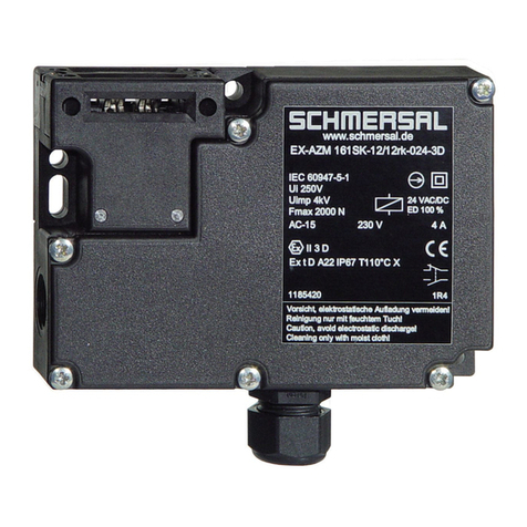
This operating instructions manual applies to the following types:
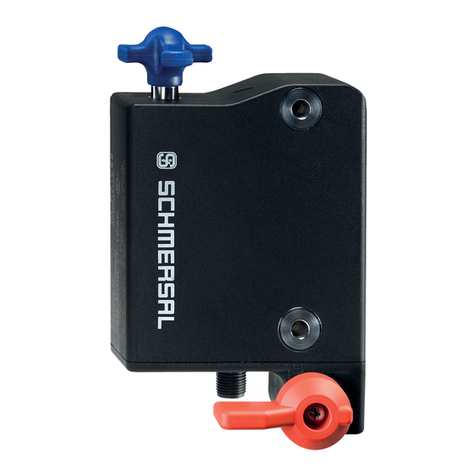
Solenoid Interlock EX-SHGV/
➀➁
/
➂
/
➃
+
➄
-2G/D
No. Option Description
➀
B Lock barrel at the bottom
L Lock barrel to left
R Lock barrel to the right
➁
D1 Additional lock barrel (front)
01 Without additional lock barrel
➂
… Key number
➃
… Key number of the additional lock barrel
➄
BO Straight actuator
BOW Angled actuator
BOR Radius actuator
BOWR Angled radius actuator
Accessories for solenoid Interlock EX-SHGV…
Material number Designation
101196682 EX-BO
101197039 EX-BOR
101197041 EX-BOW
101197043 EX-BOWR
Key-operated selector switch EX-SHGV/ESS21S2/
➀
/11033-3G/D
No. Option Description
➀
… Key number
Key-operated selector switch-interlocking device
EX-SVE
➀
/
➁
-24VDC
No. Option Description
➀
1 1 key-operated selector switches
2 2 key-operated selector switches
3 3 key-operated selector switches
➁
… Key number
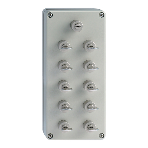
Key distribution station EX-SVM1/
➀
-
➁
/
➂
/
➃
-2G/D
No. Option Description
➀
… Key number primary key
➁
6 6 secondary keys
10 10 secondary keys
➂
… Key number secondary key
➃
E Plate for flush mounting
A Enclosure for surface mounting
Not all component variants, which are possible according to this order
code, are available.
In accordance with the Machinery Directive, the type plate of
safety components is type plate labelled "Safety component".
Only if the information described in this operating instructions
manual are realised correctly, the safety function and
therefore the compliance with the Machinery Directive
and the Explosion Protection Directive is maintained.
2.2 Special versions
For special versions, which are not listed in the order code below 2.1,
these specifications apply accordingly, provided that they correspond to
the standard version.
2.3 Destination and use
The trapped key system, consisting of the components EX-SHGV...,
EX-SHGV/ESS..., EX-SVE.... and EX-SVM..., has been designed, in
conjunction with the control part of the machine, to prevent movable
safety guards from being opened before hazardous conditions have
been eliminated and may be used on machines and systems in areas
with a risk of explosion in accordance with the EX-marking. Installation
and maintenance requirements to the standard series EN 60079 must
be met.
By turning the key-operated selector switch from the trapped position
into the removable position, the NC contacts are positively opened and
the NO contacts closed.
This combination can only be used for applications, in
which the hazardous situation is eliminated without delay
(e.g. run-on movements) after the switch-off command
from the key-operated selector switch.
The trapped key system, consisting of the components EX-SHGV…,
EX-SHGV/ESS… and EX-SVM…, has been designed to prevent, in
conjunction with the control part of the machine, movable safety guards
from being opened before hazardous conditions have been eliminated.
If the control part of the machine transmits a signal to the EX-SVE…
that the hazardous situation has been eliminated, the key can be
withdrawn from the EX-SVE…, and as a result, the movable safety
guard can be opened.
If a delay device (e.g. timer) is used to by-pass the stopping
time, a failure of this device must not cause the delay time
to be reduced.
The user must evaluate and design the safety chain in accordance with
the relevant standards and on the required safety level.
The safety switchgears are classified according to ISO 14119
as type 2 interlocking devices.
The entire concept of the control system, in which the safety
component is integrated, must be validated to the relevant
standards.
Please implement the necessary organisational measures to
ensure that only one main key is in use for each system.
The user imperatively must ensure that a key number (coding)
is only used just once in every plant (factory premises).
