Schuchmann MOMO User manual

MOMO
the bicycle for more balance
Instructions for use

Dear Customer,
At this point we would like to thank you for placing your trust in our company and
for purchasing our product.
We ask you to read through the Instructions for use carefully prior to initial com-
missioning of the product, and to observe them. Please note that guidelines and
representations in these Instructions for use may deviate from your product due to
differing equipment.
We reserve the right to make technical modications.
Important information!
Ensure that these Instructions for use remain with the product.
Your Schuchmann Team

Contents Page
1. Preparation of the therapy bicycle for use
1.1 Transport.................................................................................................................................2
1.2 Safety measures prior to use.................................................................................................. 2
1.3 Safe disposal of the packaging material................................................................................. 2
1.4 Where to keep the instructions for use....................................................................................2
2. Product description
2.1 General information.................................................................................................................3
2.2 Areas of application, use according to the intended purpose................................................. 3
2.3 Use not in accordance with the intended purpose / warning guidelines................................. 4
2.4 Equipment for basic model......................................................................................................5
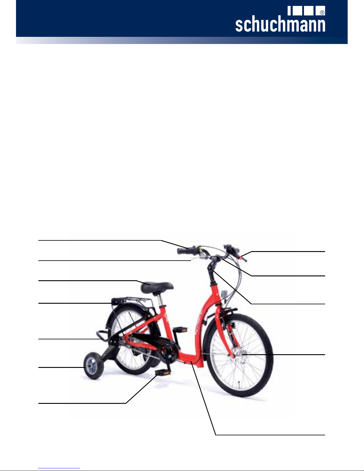
2.5 Product overview.....................................................................................................................5
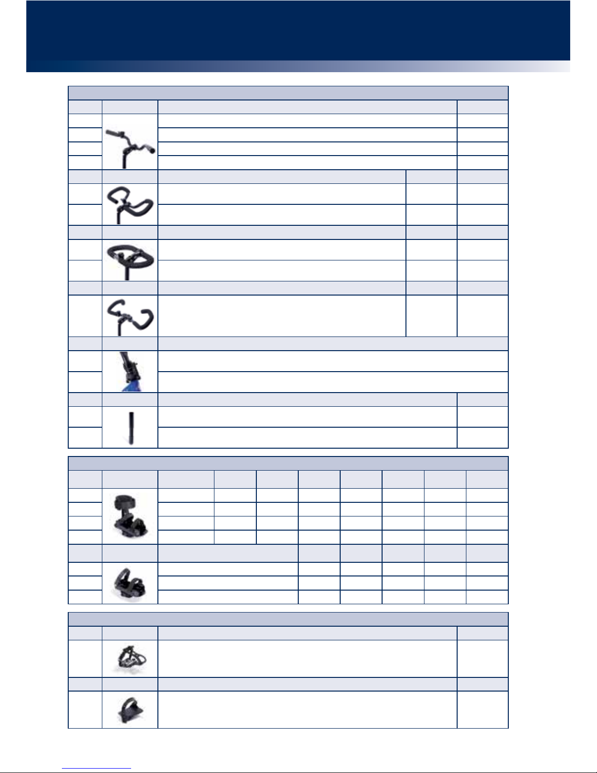
2.6 Overview of equipment / accessories.................................................................................. 6-9
2.7 Drive possibilities.................................................................................................................. 10
2.8 General settings / getting ready to ride................................................................................. 11
2.8.1 Handlebar adjustment.............................................................................................. 11
2.8.2 Saddle adjustment....................................................................................................12
2.8.3 Adjustment of the stabilisers.................................................................................... 13
2.9 The initial riding attempts...................................................................................................... 13
3. Settings
3.1 Parking brake........................................................................................................................ 14
3.2 Adjustment of the parking brake or brake blocks..................................................................14
3.3 Drum brake in front wheel.....................................................................................................15
4. Accessories
4.1 Back and pelvic guide pelotte pads.......................................................................................15
4.2 Headrest................................................................................................................................15
4.3 Push bar................................................................................................................................ 16
4.4 Parking brake for accompanying escorts..............................................................................16
4.5 Handlebar lock limiter............................................................................................................16
5. Electric drive via front wheel hub motor.....................................................................................17
5.1 Start-up assistance............................................................................................................... 17
5.2 Active electric drive incl. start-up assistance.........................................................................17
5.3 General guidelines................................................................................................................ 17
5.4 Method of function.................................................................................................................18
6. Repairs and cleaning
6.1 Care...................................................................................................................................... 18
6.2 Repairs..................................................................................................................................19
6.3 Spare parts............................................................................................................................19
6.4 Duration of usage and re-use................................................................................................19
7. Technical data................................................................................................................................20
8. Guarantee.......................................................................................................................................20
9. Identication
9.1 EC declaration of conformity................................................................................................. 21
9.2 Serial number / date of manufacture.....................................................................................22
9.3 Product version..................................................................................................................... 22
9.4 Issue of the document...........................................................................................................22
9.5 Name and address of the manufacturer, specialist dealer supplying the product.................22
1

2
1. Preparation of the therapy bicycle for use
1.1 Transport
On receiving the product, please check it for completeness, lack of faults and check
it for any transport damage.
Inspect the goods in the presence of your forwarder
Should transport damage have occurred, please cause an inventory (determination
of the faults) to be made in the presence of the forwarder. Please send a complaint
in writing to the specialist dealer responsible.
1.2 Safety measures prior to use
Correct usage of the therapy bicycle requires precise and careful training of the
accompanying person. We ask you to read through the instructions for use carefully
prior to initial commissioning of the therapy bike, and to observe them.
1.3 Safe disposal of the packaging material
The product packaging should be stored in case the product needs to be transpor-
ted again. Should you have to return the product for repairs or in case of a gua-
rantee claim, please if possible use the original box so that the product is optimally
packaged.
Otherwise, please assist in disposing of the packaging material professionally in or-
der to promote the recycling of resources. For this reason, separate the packaging
materials for recycling according to their classication.
Do not leave packaging materials unattended, as they are a possible source of
danger.
1.4 Where to keep the instructions for use
Please store these instructions for use carefully and ensure that these Instructions
for use remain with the product in case of re-use.

3
2. Product description
2.1 General information
All base frames are made of aluminium, which is non-corroding and powder-coa-
ted. All other materials used are protected against corrosion through the use of
stainless steel, aluminium or plastic.
All important parts, such as the saddle, handlebars or also the pedals can be indivi-
dually adapted to each individual disability. The special accessories allow children
and teenagers to be xed for example around the upper body or in the lower leg /
foot area.
The bicycles generally have a brake hub / back pedal hub brake on the rear wheel
(except for bicycles with a rigid sprocket) and an air pressure-independent parking
brake on the front wheel.
2.2 Application areas, use according to the intended purpose
The MOMO therapy bicycle is suitable for children and teenagers with neuromus-
cular diseases (e.g. cerebral palsy, muscular dystrophy), who cannot use normal
bicycles or vehicles, even with the aid of standard commercial stabilisers, due to
their disabilities.
It permits independent mobility; assists physiotherapist treatments and also trains
support and balance reactions as well as movement coordination.
In general, the indications for riding a bicycle should be approved by a doctor or
orthopedist. It should therefore be claried prior to procurement whether contrain-
dications exist for the patient. In general, any type of pain represents a contraindi-
cation.
Forroadworthybicycles,thefollowingcomponentsarespeciedinac-
cordancewiththeGermanRoadTrafcRegulations:
• Two brakes functioning independently of one another
• A bicycle bell with a clear ring
• Headlamps, rear lamp with reectors, large-area reectors,
pedal reectors, 2 yellow spoke reectors or white reecting rings on each
wheel, and front reectors in the design tested for the construction type.
• A bicycle trailer may only be used on bicycles with a sturdy frame and fork
construction. Also important are strong bicycle brakes at the front and rear.
Users must remember that the riding characteristics of the loaded trailer
change substantially in comparison to operation of the bicycle on its own.

4
CAUTION!
2.3 Use not in accordance with the intended purpose / warning guidelines
• Replace bent handlebars and handlebar stems immediately! Continued use
or repair means a risk of breakages.
• Correct usage of the product requires precise and careful training of the
accompanying person.
• The vehicle may only be used on stable and at ground.
• Please observe the "Technical data" in these instructions for use for the
maximum permitted patient weight.
• Always wear light-coloured and distinctive clothing!
• Always be ready to brake, in particular in steep terrain
and sections which are not easy to assess!
• Show consideration for other people who are walking or hiking!
• Do not hang loads on the handlebars; this compromises the travel safety.
• Test the fastenings for the pedal cranks and pedals regularly!
• For your own safety, we recommend that you always use your vehicle with a
helmet. Please ensure in particular that the helmet is of good quality. It should
accord at least with the legal regulations or recommendations
(Standard: EN 1078 or ANS)!
• Check that the brakes, lights and bell function properly prior to each journey!
• Ensure that your vehicle accords with the legal requirements!
• Only ride if the bicycle is in proper condition!
• Do not use headphones so that you can remain aware of warning sounds.
• If a push bar is mounted, this may only be used to guide the bicycle. The push
bar is NOT suitable for moving, lifting or tilting the bicycle!
• In wet conditions, the braking distance of your bicycle will become longer.
Therefore, always ensure that your speed remains such that you can
stop at any time.
• The therapy bicycles are not suitable for carrying a second person.
The consequences arising from such a use, which is not in accordance with
the intended purpose, shall not fall within the scope of responsibility of the
manufacturer.
• The bicycle basket may only bear loads of up to 20 kg.

2.4 Equipment for basic model
• Aluminium frame with extra-low access point
• Rim brake with locking device
• Angle adjustable handlebar stem
• Handlebar damper for stabilisation when moving straight on
• Drum brake in front wheel
• Stabiliser frame with dynamically-working stabilisers and
adjustable spring strengths
• Incl. luggage carrier
2.5 Product overview
The Fig. below is intended to show you the designation of the most important com-
ponents as well as the terms which you will nd in these Instructions for use.
Brake
Luggage carrier
Aluminium frame with
extra-low access point
Drum brake
Saddle Handlebars
Stabiliser frame
Parking brake
Gear system
Pedal
Angle adjustable
handlebar stem
Stabiliser
5

6
Saddle posts
Art. No. Saddle post Adjustment range
37 01 004 Standard saddle post - Size 1 for 12“ 7,5 cm
37 02 004 Standard saddle post - Size 2 for 16“ 15,5 cm
37 03 004 Standard saddle post - Size 3 for 20“ - 26“ 17,5 cm
Art. No. T-saddle post Adjustment range
37 01 005 T-saddle post - Size 1 for 12“ 8,5 cm
37 02 005 T-saddle post - Size 2 for 16“ + 20“ 17 cm
37 03 005 T-saddle post - Size 3 for 24“ + 26“ 25 cm
Saddle
Art. No. Saddle Width Length
37 01 001 Standard saddle - Size 1 15 cm 21 cm
37 02 001 Standard saddle - Size 2 15 cm 24 cm
37 03 001 Standard saddle - Size 3 18 cm 26 cm
Art. No. Saddle Rear width Front width Length
37 01 024 Gel saddle - Size 1 19 cm 4 cm 24 cm
37 02 024 Gel saddle - Size 2 24 cm 7 cm 27 cm
Art. No. Saddle Rear width Front width Rear length Total length
37 01 003 Saddle seat with ischium moulds - Size 1 20,5 cm 4 cm 9,5 cm 14,5 cm
37 02 003 Saddle seat with ischium moulds - Size 2 24 cm 4 cm 9,5 cm 14,5 cm
Art. No. Saddle Rear width Width in centre Front width Length
37 00 010 Unicycle saddle – banana-shaped
(Caution: min. step length increases by 2 cm) 11 cm 6 cm 8 cm 25 cm
Art. No. Saddle Rear width Front width Rear length Total length
37 00 023 Moped saddle
(Caution: min. step length increases by 2 cm) 26 cm 9,5 cm 12 cm 25 cm
Headrest
Art. No. Headrest
37 01 029 Headrest - Size 1
37 02 029 Headrest - Size 2
Holding brackets – can only be used in connection with a T-saddle post
Art. No. Holding bracket with mount Max. height* Depth
37 01 007 Holding bracket - Size 1 28 cm 30 cm
37 02 007 Holding bracket - Size 2 38 cm 30 cm
37 03 007 Holding bracket - Size 3 45 cm 30 cm
37 04 007 Holding bracket - Size 4 60 cm 30 cm
* Max. height: measured on a standard saddle up to the top edge of the back pelotte pad
Art. No. Universal bracket Width
37 02 055 Universal bracket – for harnesses when not using pelotte pads 27,5 cm
2.6 Overview of equipment / accessories

7
Torso support – can only be used in connection with a holding bracket
Art. No. Dynamic back pelotte pad – padded, with strap and mount Width
37 01 008 Dynamic back pelotte pad - Size 1 20 - 30 cm
37 02 008 Dynamic back pelotte pad - Size 2 25 - 35 cm
37 03 008 Dynamic back pelotte pad - Size 3 30 - 40 cm
Art. No. Width adjustable back pelotte pad – padded, incl. mount Width
37 01 025 Width adjustable back pelotte pad - Size 1 20 - 28 cm
37 02 025 Width adjustable back pelotte pad - Size 2 25 - 33 cm
37 03 025 Width adjustable back pelotte pad - Size 3 30 - 36 cm
Harness system
Art. No. Manual xation – for all handlebars Front width
37 00 054 Manual xation - Size 0 8,5 cm
37 01 054 Manual xation - Size 1 10 cm
37 02 054 Manual xation - Size 2 12 cm
37 03 054 Manual xation - Size 3 14 cm
Art. No. Chest strap – for the width adjustable back pelotte pad Width Length
37 01 050 Chest strap - Size 1 5 cm 18,5 cm
37 02 050 Chest strap - Size 2 6,5 cm 25,5 cm
37 03 050 Chest strap - Size 3 7 cm 30,5 cm
Art. No. Fixation vest harness – for the width
adjustable back pelotte pad Inside width Total width Side height Total height
37 01 051 Fixation vest harness - Size 1 8 cm 25 cm 10 cm 28 cm
37 02 051 Fixation vest harness - Size 2 9 cm 30 cm 12 cm 30 cm
37 03 051 Fixation vest harness - Size 3 12 cm 34 cm 16 cm 35 cm
Art. No. Groin strap, T-shaped – for the width
adjustable pelvic pelotte pad
Seat surface
width Front width Seat surface
length Total length
37 01 052 Groin strap, T-shaped - Size 1 24 cm 23 cm 15 cm 32 cm
37 02 052 Groin strap, T-shaped - Size 2 26 cm 26 cm 17 cm 34 cm
37 03 052 Groin strap, T-shaped - Size 3 28 cm 28 cm 19 cm 38 cm
Art. No. 4-point pelvic strap – for the
width adjustable pelvic pelotte pad
Width of exte-
rior parts
Centre sec-
tion width
Length of
exterior part
Centre sec-
tion length
37 01 053 4-point pelvic strap - Size 1 7 cm 7 cm 12 cm 12 cm
37 02 053 4-point pelvic strap - Size 2 9 cm 8,5 cm 13 cm 14 cm
37 03 053 4-point pelvic strap - Size 3 11,5 cm 11 cm 15 cm 16 cm
Pelvic support – can only be used in connection with a holding bracket
Art. No. Dynamic pelvic guidance pelotte pad – padded, with strap and mount Width
37 01 009 Dynamic pelvic guidance pelotte pad - Size 1 20 - 30 cm
37 02 009 Dynamic pelvic guidance pelotte pad - Size 2 25 - 35 cm
37 03 009 Dynamic pelvic guidance pelotte pad - Size 3 30 - 40 cm
Art. No. Width adjustable pelvic guidance pelotte pad – padded, with mount Width
37 01 026 Width adjustable pelvic guidance pelotte pad - Size 1 20 - 28 cm
37 02 026 Width adjustable pelvic guidance pelotte pad - Size 2 25 - 33 cm
37 03 026 Width adjustable pelvic guidance pelotte pad - Size 3 30 - 36 cm

8
Foot cups
Art. No. Foot cups with
leg guidance
Min. front
width
Max. front
width
Min. rear
width
Max. rear
width Length Min. height of
leg guidance
Max. height of
leg guidance
37 01 018 Size 1 8,7 cm 10,4 cm 5,7 cm 7,4 cm 17,4 cm 15 cm 18,5 cm
37 02 018 Size 2 9,5 cm 12 cm 6,7 cm 9,2 cm 20,1 cm 18 cm 22 cm
37 03 018 Size 3 11,5 cm 14 cm 8,1 cm 10,6 cm 23,8 cm 21 cm 26 cm
37 04 018 Size 4 11,5 cm 14 cm 8,1 cm 10,6 cm 23,8 cm 28 cm 36 cm
Art. No. Foot cups Min. front
width
Max. front
width
Min. rear
width
Max. rear
width Length
37 01 017 Foot cups - Size 1 8,7 cm 10,4 cm 5,7 cm 7,4 cm 17,4 cm
37 02 017 Foot cups - Size 2 9,5 cm 12 cm 6,7 cm 9,2 cm 20,1 cm
37 03 017 Foot cups - Size 3 11,5 cm 14 cm 8,1 cm 10,6 cm 23,8 cm
Pedals
Art. No. Pedals Depth
37 00 013 Foot xation pedals – with bike toe clips and compensation 13 cm
Art. No. Pedals Width
37 00 014 Home trainer pedals 12 cm
Handlebars
Art. No. Classic handlebars – black Width
37 01 011 Classic handlebar for 12“ 47 cm
37 02 011 Classic handlebar for 16“ 50 cm
37 03 011 Classic handlebar for 20“ 58 cm
37 04 011 Classic handlebar for 24“-26“ 61 cm
Art. No. Touring handlebars Width Depth
37 01 012 Touring handlebar - Size 1 55 cm 17 cm
37 02 012 Touring handlebar - Size 2 58 cm 17 cm
Art. No. Round handlebars Width Depth
37 01 013 Round handlebar - Size 1 39 cm 17 cm
37 02 013 Round handlebar - Size 2 46 cm 24,5 cm
Art. No. Multifunctional handlebars – suitable for 20“ - 26“ min. Width max. Depth
37 02 014 Multifunctional handlebar 34 cm 62 cm
Art. No. Steering angle limiter – adjustable up to direction determination
37 01 006 Steering angle limiter - Size 1 for 12“
37 03 006 Steering angle limiter - Size 2 for 16“ - 26“
Art. No. Handlebar extension Length
37 01 022 Handlebar extension - Size 1 for 12“ 10 cm
37 02 022 Handlebar extension - Size 2 for 16“ - 26“ 10 cm

9
Steering
Art. No. Push bar – height adjustable and removable, with integrated twist lock
38 01 009 Push bar for 12“
38 02 009 Push bar for 16“
38 03 009 Push bar for 20“ - 26“
Art. No. Parking brake for accompanying escorts – can only be used in connection with a push bar
38 00 011 Parking brake for accompanying escorts
Art. No. Steering for accompanying escorts – via redirecting bar, including steering angle limiter
(can only be used in connection with a push bar)
38 01 010 Steering for accompanying escorts for 12”
38 02 010 Steering for accompanying escorts for 16“
38 03 010 Steering for accompanying escorts for 20“ - 26“
Lights system
Art. No. Retrotting of a lights system
37 02 021 Retrotting of a lights system for 16“ + 20“ – with side runners and reectors acc. StVo (German Road Trafc Act)
37 01 021 Retrotting of a lights system for 16“ - 20“ – with hub dynamo and reectors acc. StVo (German Road Trafc Act)
37 04 021 Lights system with hub dynamo for 24“ + 26“
Electric drive
Art. No.
Active electric drive via front wheel hub motor
• Incl. start-up assistance and pedal sensor
• To be activated using the twist handle by the rider
• Incl. 36V lithium ion battery (6.4AH)
• Max. speed approx. 20 km/h (12 km/h at 20“)
38 03 125 Active electric drive via front wheel hub motor for 20“
38 04 025 Active electric drive via front wheel hub motor for 24“
38 05 025 Active electric drive via front wheel hub motor for 26“
Basket
Art. No. Basket
38 01 019 Basket for 12“ + 16“
38 03 019 Basket for 20“ + 24“
38 05 019 Basket for 26“
Retrot set
Art. No. Stabiliser frame with dynamic supports and adjustable spring strength
38 01 101 Stabiliser frame for 12“
38 02 101 Stabiliser frame for 16“
38 03 101 Stabiliser frame for 20“
38 04 101 Stabiliser frame for 24“
38 05 101 Stabiliser frame for 26“

10
2.7 Drive possibilities
The MOMO therapy bicycle can be equipped with
the following drives:
Rigid sprocket
The rigid sprocket means that the user constant-
ly has to pedal, and permits riding forwards or
backwards.
Freewheel brake hub (with backpedal brake)
The freewheel brake hub allows the user to stop and start pedalling as they wish.
They can brake by pedalling backwards.
Extra-light transmission
An extra-light transmission can be selected for all types of drive. Here a larger pini-
on on the rear axle permits improved force transmission and thus makes it easier
for the user to start pedalling.
3 or 7-gear freewheel brake hub (with backpedal brake)
Using the 3 or 7-gear freewheel brake hub, the user can stop and start pedalling
at will. They can brake by pedalling backwards. The user-friendly 3 or 7-gear hub
gear system is suitable for any terrain and also permits switching of gears when
the bicycle is at a standstill. Switching takes place using the twist grip shifter on the
handlebars.
3 or 7-gear neutral hub (without backpedal brake)
Using the 3 or 7-gear neutral hub, the user can stop and start pedalling at will. They
can also bring the pedals into the optimum position to start using the neutral gear.
The user-friendly 3 or 7-gear hub gear system is suitable for any terrain and also
permits switching of gears when the bicycle is at a standstill. Switching takes place
using the twist grip shifter on the handlebars.
3-gear freewheel brake hub, can be ridden backwards
The user can stop and start pedalling at will with the 3-gear freewheel brake hub.
In addition, they can ride backwards. The user-friendly 3-gear hub gear system is
suitable for any terrain and also permits switching of gears when the bicycle is at a
standstill. Switching takes place using the twist grip shifter on the handlebars.

11
2.8 General settings / getting ready to ride
The MOMO therapy bicycle is supplied completely assembled. Prior to initial use,
however, the following pre-settings must be made.
2.8.1 Handlebar adjustment
Height of handlebars
You can adjust the height of the handlebars. To
do this, loosen the hexagon socket (A) and adjust
the stem (B) to the required height. The stem will
become adjustable if you tap the spindle head
lightly with a hammer. Then re-tighten the expan-
der bolt.
Ensure that the marking for the minimum insertion depth (C) remains
on the stem in the headtube and therefore cannot be seen.
Handlebar adjustment
Loosen the clamping screw (D), bring the handlebars into the correct position and
then re-tighten the clamping screw.
In order to change the tilt angle on the stem, please loosen the clamping screw (E).
In this way you can change the distance between the saddle and the handlebars,
and adjust the required handle height. Then rmly re-tighten all the screws again.
After each adjustment, please re-tighten all screw connections!

12
During adjustment, the saddle post may not be pulled out over the
respectivemarking,asinthiscasesufcientclampingcannotbe
guaranteed. The markings are in part designed differently.
Adjusting the saddle horizontally
In order to check the horizontal saddle position,
turn the pedal crank horizontally forwards and
put the foot (while the rider is sitting on the sadd-
le) onto the pedal. Once the lower leg is verti-
cal, the saddle position is correct. You can also
loosen the two nuts (B) under the saddle, push
the saddle to the rear or forwards and re-tighten
the nuts.
2.8.2 Saddle adjustment
Saddle height
The height of the saddle can be adjusted on the
saddle support tube by pulling the saddle post
in or out. To do this, please loosen the clamping
screw (A) and bring the saddle to the correct
height; align it and then re-tighten the clamping
screw.
The saddle height is correctly adjusted if the ball of the rider's foot is standing on the
pedal at the lowest position, and the knee is not quite straightened out.
After each adjustment, please re-tighten all screw connections!

13
2.8.3 Adjustment of the stabilisers
The stabilisers are equipped with spring elements
which can be adjusted from soft to hard. To do
this, loosen the screw (A) and move the spring
element in the slot. Moving towards the stabiliser
increases the spring hardness.
By loosening the two screws (B), the stabilisers
can be adjusted so that they are off the oor.
Tighten the screws again after all adjustments.
In addition, the spring deection can be limited
with an adjustable end stop. To do this, loosen
the counternut (C) under the support. By screw-
ing the screw (D) in or out, the spring deection
can be readjusted. Then retighten the counternut
again.
A
B
D
C
2.9 The initial riding attempts
Once you have adjusted the bicycle components to your body size, it is time to ride
off.
Please remember that you must in particular practice with someone supervising
you how to deal with riding around curves with the therapy bicycle prior to setting
off on your own, as this is where the risk of accidents is greatest.
Always ride around curves as slowly as possible. Please also remember that the
widest part of your bicycle is behind you. Therefore, practice using appropriate
obstacles so that you learn to estimate the width of your bicycle better.
After each adjustment, please re-tighten all screw connections!

14
3. Settings
3.1 Parking brake
The brake lever for the parking brake, which is
intended to make it easier for the user to climb on
and off the bicycle, is located the left-hand side of
the handlebars. The function of the lever is simi-
lar to a normal brake lever. If however the brake
should be locked in parking position, the claw (B)
must be pressed into the ratchet with the brake
lever pulled (A). Loosen the locking device by pulling the brake lever (A).
B A
Always ensure that the brake or the brake blocks function correctly
and have been adjusted (see Point 3.2).
3.2 Adjustment of the parking brake or brake blocks
Ensure that the function immediately replaces
the cantilever (V) brake on actuation of the lever,
taking the necessary backlash into account. Due
to "settling" of the cables and the natural wear
on the brake blocks, it is necessary to set the
brake or replace the brake blocks after a certain
amount of time.
Each gap between the rim and the brake lining
should not be larger than 1.5 mm. If the brake
blocks are not accurately aligned with the rim
edge, you must readjust it accordingly. To do this, loosen the clamping screw (C),
press the brake blocks together by hand, pull the cable taut and then re-tighten the
clamping screw.
Leave this work to your specialist dealer in case of any uncertainty.
After each adjustment of the cantilever (V) brake, carry out a brake test.
The brake blocks may only be replaced by ones in an identical design.
Observe the manufacture name or marking and the type designation.
New brake blocks do not achieve the required braking effect until they have
been used multiple times.
C

15
3.3 Drum brake in front wheel
On the bicycle designs with drum brakes, the bra-
ke lever for the drum brake is located on the right-
hand side of the handlebars.
Always only use the front wheel drum brake when
riding in connection with the rear wheel brake.
Basically, we recommend that the front and rear
axle brake are actuated simultaneously and that
the braking force is distributed as you think t.
4. Accessories
4.1 Back and pelvic guide pelotte pads
All back and pelvic guide pelotte pads can only be
used in connection with a holding bracket.
For depth adjustment of the pelotte pads, please loo-
sen the screws (A) on the right and left-hand sides of
the support under the saddle, and bring the pelotte
pad into the required position.
The angular adjustment of the pelotte pads takes
place after loosening the screw (B) on the support.
The pelotte pads are adjusted in height after loose-
ning the screw (C) on the respective support.
After each adjustment, please re-tighten all screw connections!
4.2 Headrest
The headrest is mounted on the holding bracket and
can be adjusted in height, depth and angle.
In order to adjust the height, loosen the screw (D),
bring the headrest into the required position and re-
tighten the screw. The angle can be adjusted by loo-
sening the screws (E). By loosening the screws on
the right and left-hand side of the bracket under the
saddle, the depth of the headrest can be set. D
E

16
After each adjustment, please re-tighten all screw connections!
4.3 Push bar
The push bar is height adjustable, removable and
equipped with an integrated antirotation lock.
In order to adjust the height, please loosen the
clamp (A) and bring the push bar into the requi-
red height. In order to remove the entire push bar,
please loosen the clamp (B). Please ensure on
insertion that the push bar is inserted up to its
limit into the push handle holder, and cannot be
rotated.
A
B
Use push bar only to guide the bicycle! The push bar is NOT suitable
for moving, lifting or tilting the bicycle!
4.4 Parking brake for accompanying
escorts
The parking brake (which can only be used in
conjunction with the push bar), ensures that the
therapy bicycle does not roll away inadvertently.
The function of the lever is similar to a normal
brake lever. For this reason, the parking brake
can also be used as a normal brake. If however
the brake should be locked in parking position, the claw (D) must be pressed into
the ratchet with the brake lever pulled (C). Loosen the locking device by pulling the
brake lever (C).
D
C
Always ensure that the brake or the brake blocks function correctly
and have been adjusted (see Point 3.2).
4.5 Handlebar lock limiter
The handlebar lock limiter can be adjusted to de-
termine the direction of travel.
In order to adjust the handlebar lock limiter, ple-
ase loosen all grub screws (E) and bring the stop-
per (F) into the required position.
You can determine the direction by moving both
stoppers (F) towards the bar (G) and tightening
them.
E
F
G

17
5. Electric drive via front wheel hub motor
For many tricycle and therapy bicycle riders, situ-
ations repeatedly occur during use of a bicycle in
which physical force proves insufcient and external
support is required. Here we have congured seve-
ral application variations of highly-modern electric
drives in order to further increase independence and
mobility.
Below you will nd brief explanatory function de-
scriptions of the individual variations. We are happy
to conduct face to face meetings or telephone talks with you to assist in the selec-
tion of a solution tailored to your individual requirements or in the development of
a special construction.
5.1 Start-up assistance
This E-bike solution is orientated towards users who are capable cognitively of
operating the control or the twist grip. The start-up assistance provides support in
start-up situations and for coping with inclines through motor support. The user can
start up using the twist grip, and can then accelerate to max. 3 km/h. The pedalling
resistance is minimal, and the user can initiate the pedalling movement. A higher
riding speed can then be achieved through muscle power, after which the motor
runs without load.
5.2 Active electric drive incl. start-up assistance
Using the active drive, users achieve maximum mobility and range. The start-up
situation can be managed through the twist grip, and the bicycle accelerates to up
to 6 km/h without pedalling assistance. On pedalling, a pedal sensor releases a
further speed range which provides support up to 20 km/h. The supporting force is
to be controlled during use through the rider with the twist grip.
5.3 General guidelines
The electric drive via front wheel hub motor is to be actuated by the rider using the
twist grip. This makes starting off easier and supports the pedal force as you ride.
In test rides, carefully try out the additional acceleration of your new bicycle. Only in
this way can you get used to the forces you produce, the motor force and the riding
speed aimed for.
Prior to riding, please ensure that the battery is as fully charged as possible (obser-
ve the charging level display, see the enclosed original operating instructions by the
battery component manufacturer).

18
5.4 Method of function
Start / travel
First set the key switch with the key to "ON" (A).
Then remove the key again so that it is not lost du-
ring travel. You can nd the key under the control.
beneath the luggage carrier.
Now put the on/off switch (B) on the twist grip into
the "ON" position (the green lamp will light up). By
turning the twist grip gently, the motor is interconnec-
ted and will accelerate without you pedalling to max.
6 km/h (16" and 20" reduced to 3 km/h).
End of travel
Turn back the twist grip or simply let it go. Then set
the on/off switch (B) on the twist grip and the key
switch on the control to "OFF":
A
B
6. Repairs and cleaning
6.1 Care
In order to retain the functional safety and the appearance of the bicycles, it must
be regularly maintained; here the following guidelines must be observed:
• Never allow dirt to dry onto the bicycle, but always remove it with water and a
soft cloth or sponge. Do not use high-pressure cleaners for washing, or you
may damage the bearings, the paintwork or the decorations.
• Do not use aggressive cleaning agents. Use a mild detergent solution to clean.
• Use a standard commercial spray disinfectant to disinfect the saddle,
handlebars and other upholstered parts which come into contact with the skin.
• Repair paintwork damage immediately.
• In particular in winter, store the bicycle in a dry room with a consistent
temperature.
• Prior to extended storage of the tyres, check them and, if necessary, pump
them up to the air pressure recommended by the manufacturer (see Point 7).
Other manuals for MOMO
2
Table of contents
Other Schuchmann Bicycle manuals