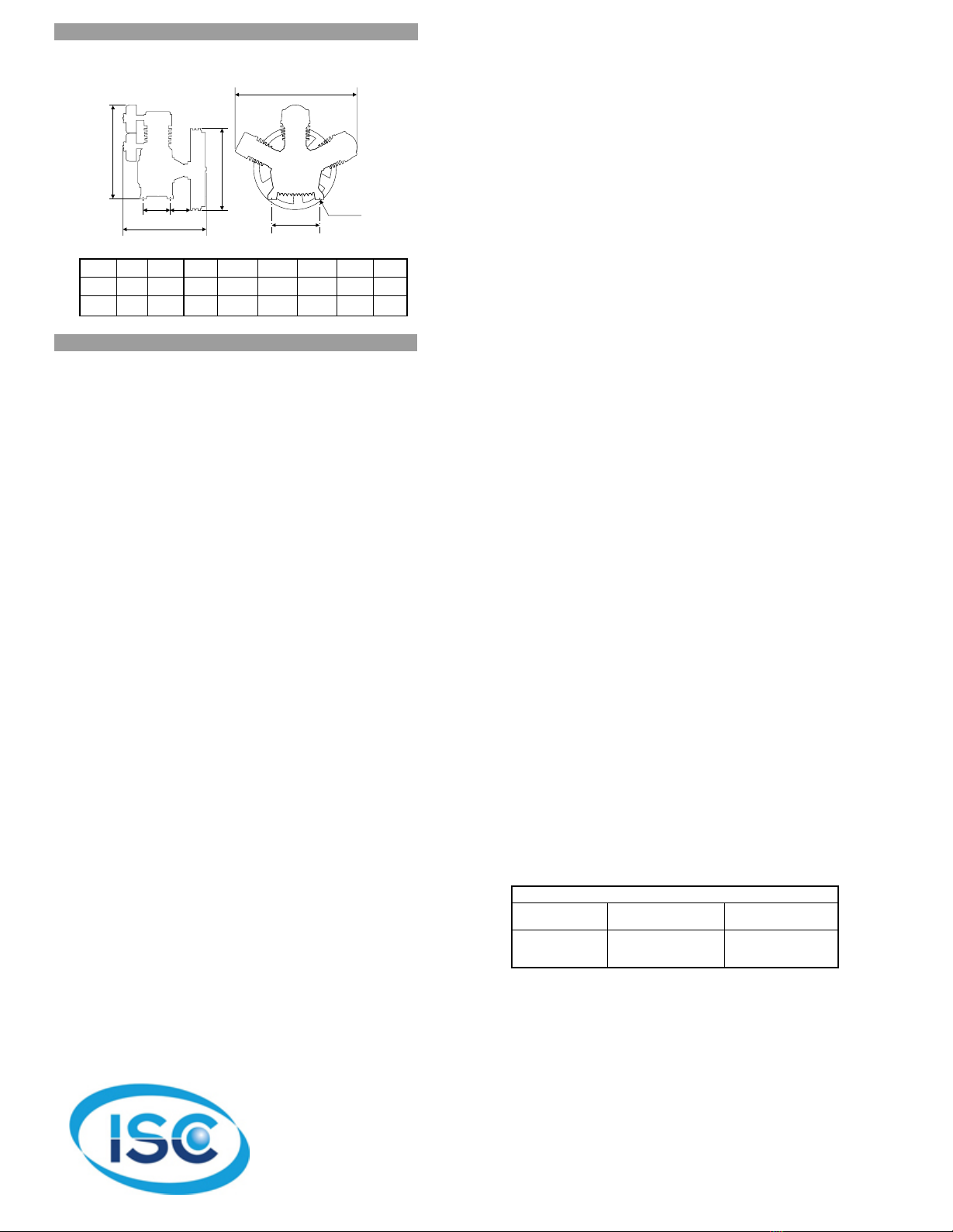
manuals.online logo
Brands
  1. Home
  2. •
  3. Brands
  4. •
  5. Schulz
  6. •
  7. Air Compressor
  8. •
  9. Schulz MSW 60 MAX User manual

Schulz MSW 60 MAX User manual

Other Schulz Air Compressor manuals

Schulz AIR PLUS User manual

Schulz

Schulz AIR PLUS User manual

Schulz CSA 7.8/17-PANCAKE User manual

Schulz

Schulz CSA 7.8/17-PANCAKE User manual

Schulz MSL 20 MAX User manual

Schulz

Schulz MSL 20 MAX User manual

Schulz Audaz MCSV-20 AP User manual

Schulz

Schulz Audaz MCSV-20 AP User manual

Schulz AIR PLUS 12V User manual

Schulz

Schulz AIR PLUS 12V User manual

Schulz MSV 30 SA User manual

Schulz

Schulz MSV 30 SA User manual

Schulz Air Pluse 12V Duo User manual

Schulz

Schulz Air Pluse 12V Duo User manual

Schulz 20120HWV80X User manual

Schulz

Schulz 20120HWV80X User manual

Schulz MSL 40 MAX User manual

Schulz

Schulz MSL 40 MAX User manual

Schulz CSV15 MAX/200 User manual

Schulz

Schulz CSV15 MAX/200 User manual

Schulz MSV 20 SD Owner's manual

Schulz

Schulz MSV 20 SD Owner's manual

Schulz Compact SRP 3005 User manual

Schulz

Schulz Compact SRP 3005 User manual

Schulz MS 3/30 User manual

Schulz

Schulz MS 3/30 User manual

Schulz 12V BATTERY AIR COMPRESSOR User manual

Schulz

Schulz 12V BATTERY AIR COMPRESSOR User manual

Schulz MSI 8,5/25 AIR PRO Configuration guide

Schulz

Schulz MSI 8,5/25 AIR PRO Configuration guide

Popular Air Compressor manuals by other brands

Craftsman 919.724591 owner's manual

Craftsman

Craftsman 919.724591 owner's manual

Atlas Copco GA 30+ Instruction book

Atlas Copco

Atlas Copco GA 30+ Instruction book

Hitachi Highly WHP11500VSDPC9EQ installation manual

Hitachi

Hitachi Highly WHP11500VSDPC9EQ installation manual

Craftsman 919.167810 owner's manual

Craftsman

Craftsman 919.167810 owner's manual

Yamato 24/2 M1CD instruction manual

Yamato

Yamato 24/2 M1CD instruction manual

Clarke 2242117 Operation & maintenance instructions

Clarke

Clarke 2242117 Operation & maintenance instructions

Sparmax DC-25XR user manual

Sparmax

Sparmax DC-25XR user manual

Briggs & Stratton Air Compressor Operator's manual

Briggs & Stratton

Briggs & Stratton Air Compressor Operator's manual

Fini F3GST2TK Operator's manual

Fini

Fini F3GST2TK Operator's manual

Campbell Hausfeld RP3300 Easy setup guide

Campbell Hausfeld

Campbell Hausfeld RP3300 Easy setup guide

Ingersoll-Rand UP6 20 HP Option manual

Ingersoll-Rand

Ingersoll-Rand UP6 20 HP Option manual

Parkside PKO 270 A1 operating instructions

Parkside

Parkside PKO 270 A1 operating instructions

Clas Ohlson QIE-ZTH-15 manual

Clas Ohlson

Clas Ohlson QIE-ZTH-15 manual

Ferm CRM1046 Original instructions

Ferm

Ferm CRM1046 Original instructions

BE AC153 Operation manual

BE

BE AC153 Operation manual

RIDGID OF25150A Operator's manual

RIDGID

RIDGID OF25150A Operator's manual

Johnson Controls QUANTUM LX Setup

Johnson Controls

Johnson Controls QUANTUM LX Setup

Ring Automotive RAC700 instructions

Ring Automotive

Ring Automotive RAC700 instructions

manuals.online logo
manuals.online logoBrands
  • About & Mission
  • Contact us
  • Privacy Policy
  • Terms and Conditions

Copyright 2025 Manuals.Online. All Rights Reserved.

COMPRESSOR MSW 60 MAX
COMPRESSOR MSW 60 MAX TWO STAGES
175 PSIG
TWO STAGES
175 PSIG
CAST IRON INDUSTRIAL COMPRESSORS
TECHNICAL DATA
TECHNICAL DATA
DISPLACEMENT
cfm
MAX. PRESSURE
psig
MOTOR
hp
BELT OIL CAP. WEIGHT
IN LBS
DISCHARGE
SIZE
RPM
60 175 1020 15 2-B 1.5 1.58 276 1” BSPMSW 60 MAX
MODEL MOTOR PULLEY
2 POLES IN QT
150 5.9
mm inch
35 36 27
26
4
25
24
23
22
20
15
11
10
7
53
11
8
2
1
4
6
9
21
4
28
18
19
19
17 17
4
32-31
30-29
16
14
13
11
12
8
A
43 59
57
58
38
41 40
64 37 34
56
39
42
33
33
34 37
34 37
B
51
63
49
50
B
A
61 52
60
16
55
51
T8 T1
T2
T2
T3
T5
T4
T7
T6
T9
T9
T10
T11
TABLE1-TORQUE
ESPECIFICATION FOR BOLTS
T7
T10
T11
T6
T9
HP-LP 34/37
HP 37
T5
T8
T4
T3
T2
T1
Position lbf.IN
30443
8
2
27
11
13
22
56
59
704
70
158
1215
141
334
19
185
44
264 30
34
80
8
18
137
16
38
2.2
21
5
N.m
47
53 45 44 65
62
48
46
LP 4.3/4" cylinder
HP 90 mm cylinder
LP 4.3/4" valve plate kit
LP 4.3/4" valve plate
HP 90 mm valve plate
LP 4.3/4" cylinder cover with breather
LP 4.3/4" cylinder cover
HP 90 mm cylinder cover
LP UNC 3/8" x 1.1/2" head bolt
No. 1 short intercooler
No. 2 long intercooler
Intercooler kit
3/4" nut for intercooler
Intercooler holder
1/4" crankcase breather tube
NPT 1/8" x 1/4" straight connection
1/4" ring kit
3/4" x 1/2" straight connection
3/4" x 3/4" straight connection
1/8" LP ASME safety valve
Centrifugal unloading valve
M6x1x55Allen hex bolt
Filter element
Air filter
HP 5/16" x 1.1/2" Allen hex bolt
BSPT 3/4" x 100 niple
Intercooler adaptor
BSP 90 3/4" elbow
Straight fitting
Washer kit
HP 1/8" ASME safety valve
Pulley (not shown)
0
02
01
02
02
01
01
01
01
12
01
01
01
04
02
01
01
01
02
02
02
01
05
02
02
06
01
01
02
01
01
01
01
35
36
37
38
39
40
41
42
43
44
45
46
47
48
49
50
51
52
53
54
55
56
57
58
59
60
61
62
63
64
65
-
709.1306-0
709.1308-0
830.0955-0
809.1028-0
809.1027-0
709.1272-0
709.1390-0
709.1303-0
*
709.1322-0/C
709.1322-0/L
709.1322-0
21011004
21029003
830.0340-5
003.0054-3
830.0599-8
21011001
21011002
022.0177-0
022.0174-0
013.0752-0
007.0118-0
007.0116-0
383.0111-0
21011009
20517005
003.0111-6
60259501
830.1032-0
022.0189-0
709.1323-0
Flywheel
UNC 1/4" x 3/4" head bolt
Flange cover
Crankcase gasket kit
Oil seal
Lock washer and nut
33109 bearing
NC 1/2" x 1" head bolt
Flange
32211 bearing
Crankshaft
Key
UNF 3/8" x 3" head bolt
Crankshaft counter weight
Auxiliary connecting rod pin
Connecting rod
Master connecting rod
Connecting rod inner bushing
Connecting rod bushing
Counter weight with centrifugal mechanism
Counter weight kit with centrifugal mechanism
UNF 5/16" x 1.1/4" head bolt
Crankcase
3/4" oil level sight
3/8" plug
Crankcase cover
UNC 5/16" x 3/4" head bolt
3/4" plug
LP 4.3/4" piston
HP 90 mm piston
LP 90 mm ring kit
HP 4.3/4" ring kit
Upper gasket kit
HP 90 mm valve plate kit
01
04
01
01
01
01
01
18
01
01
01
01
02
01
02
02
01
02
05
01
01
02
01
01
01
01
06
01
02
01
01
02
01
01
1
2
3
4
5
6
7
8
9
10
11
12
13
14
15
16
17
18
19
20
21
22
23
24
25
26
27
28
29
30
31
32
33
34
709.1307-0
*
20505001
830.1033-0
60082501
830.0932-0
60154502
*
20504001
60154501
830.0933-0
60267503
*
20508005
830.0934-0
30008502
830.0930-0
60152502
60152501
30007001
830.0937-0
*
20501002
830.0775-0
003.0029-2
709.1316-0
*
003.0031-4
60273501
830.1000-0
000.0077-0
000.0080-0
830.1001-0
830.1002-0
BARE PUMP PARTS
BARE PUMP PARTS
CODE CODE
QUANTITY QUANTITY
DENOMINATION DENOMINATION
No. No.
APRIL/03 025.0325-0
CT 178
* Part available in the market - not sold by Schulz
Note: HP = high pressure LP = low pressure
54
54
IN
MSW 60 MAX
ABC D E F G H
550
21.6
120
4.8
218
8.6
500
19.7
320
12.6
14
0.6
620
24.5
740
29.1
mm
inch
INSTALLATION AND LOCATION
OPERATION
1. Installation:
2. Electrical connection:
Install the compressor in a covered, well
ventilated area, free of dust, toxic gases, humidity or any
other kind of pollution. The compressor should be located no
closer than 32" (800mm) from a wall or any other obstacle
that could interfere with the air flow through the fan. This
distance will also make maintenance easier. Place the
compressor on a leveled surface. Rotation of the flywheel
must be in the direction of the arrow cast into the flywheel.
The maximum ambient temperature recommended while
working is 104ºF or 40ºC. If necessary, install an exhaust fan
to guarantee fresh air and to dissipate heat.
Before making the electrical connections, check oil level and
top-up lubricating oil. For type of oil, see table at the end of
these instructions.
The country's valid electrical
standards must be followed regarding Low Voltage Electrical
Installation.
Before turning on the compressor,
check the crankcase oil level. It must be in the middle of the
OIL LEVEL SIGHT. As to the type of oil to be used and the
recommended change intervals, check at "Lubrication" and
as to its volume, check the Technical Data Table.
Turn on the electrical start key and let your
compressor run for about 10 (ten) minutes, what will keep
the tank's internal pressure or compressed air around 20
psig. This will optimize a homogeneous lubrication of the
parts.
1. Initial start procedure:
2. Start:
DIMENSIONS
DIMENSIONS
INSTALLATION AND OPERATION INSTRUCTIONS
MAINTENANCE
WARNING
DAILY
WEEKLY
MONTHLY
QUARTERLY
ANNUALLY
LUBRICATION
NOTE:
RECOMMENDED LUBRICANT OILS FOR SCHULZ AIR PUMPS
-
-
-
-
-
-
-
- ASME s
-
-
-
-
-
-
-
Turn off power before servicing and be sure the air tank is unloaded. These
instructions are based on normal operating conditions. If the compressor is
located in an exceedingly dusty area, increase the frequency of all
inspections.
Inspect the compressor visually.
Check oil level and add some if necessary, before turning the
compressor on.
Drain moisture from the piping system.
Be sure there is no excessive or unusual vibration or noise.
Remove and clean intake air filters; do not wash the filter element.
Check V-belts for tightness. Belt tension should be adjusted to allow
approximately 3/8" to 1/2" (9 to 13 mm) deflection with normal thumb
pressure.
Clean cylinders externally, cylinder head, motor, fan blade, tubing, and tank.
afety valve should be tested manually to see if it is working properly.
Check entire system for air leakage around fittings, etc by using water and
soap lather.
Check the pressure switch operation.
Check for oil contamination and change it if necessary.
Change the air filter element every 300 working hours or quarterly.
(Whichever occurs first).
Fasten bolts and nuts as required. (See Table 1)
- Change oil more frequently if compressor is located in a very dirty
environment.
Test and calibrate the pressure switch, pressure gauge, pilot valve,
discharge valve and ASME safety valve according to their own technical
standards. These parts must be removed from the tank and pump to be
tested.
Inspect and clean the suction and discharge valve(s) plate(s) every 1000 (one
thousand) working hours (whichever occurs first), located between the
cylinder and its cover and, if necessary, replace it (them) according to the
operation conditions.
- The first oil change should be made after 8 hours of operation.
- The second oil change after 40 hours of operation.
- The third and following exchanges should be made after 200 hours of
operation, or 60 (sixty) days, whichever occurs first.
Heavy Duty and multi-viscous oils are not adequate for Schulz air
compressor's lubrication. The same applies to oils that tend to emulsify.
We recommend good industrial oil for air compressors, with rust and
oxidation inhibitors and high viscosity level (from 90 to 95), SAE or ISO, as
indicated in the table below:
- WHILE RUNNING IN A PERIOD OF ABOUT 100 WORKING HOURS THE OIL
LEVEL SHOULD BE CAREFULLY CHECKED.
DISTRIBUTOR
Below 32 F
Below 0 C
0
0
32 Fto68 F
0 C to 20 C
00
00
68 F to 104 F
20 Cto40 C
00
00
SAE 10W
or
ISO 32
SAE 20W
or
ISO 68
SAE 30
or
ISO 100
AMBIENT TEMPERATURE F ( C)
00
CB
H
G
D
ØF
E
A
ISC Sales
isccompressedair.com
877-602-0010
972-964-2700