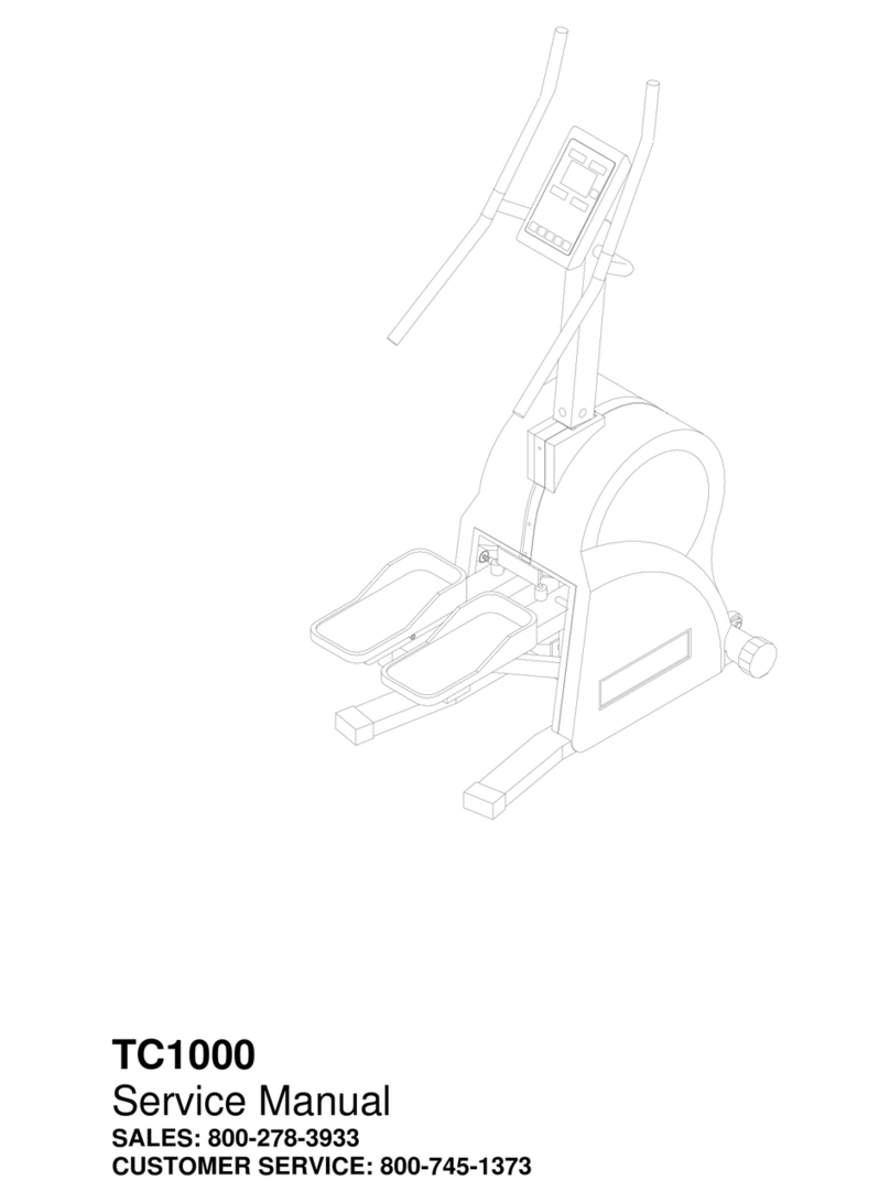
SCIFIT PRO1 Sport Operating and safety instructions
Other SCIFIT Fitness Equipment manuals
SCIFIT
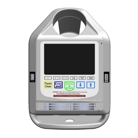
SCIFIT Intelli-fit Troubleshooting guide
SCIFIT
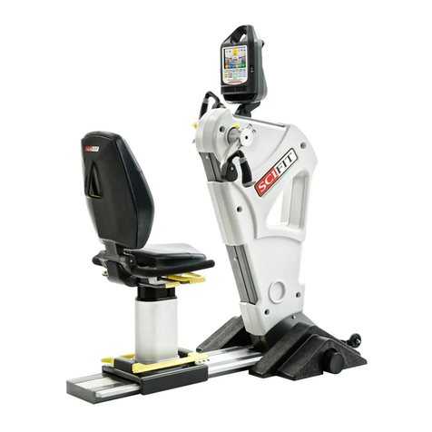
SCIFIT PRO2 Mounting instructions
SCIFIT
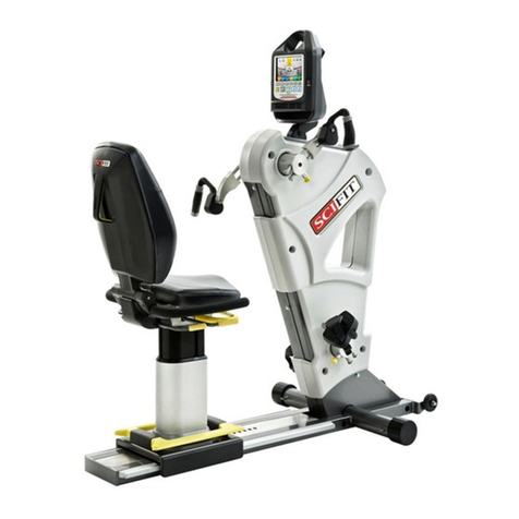
SCIFIT PRO2-INT Series User manual
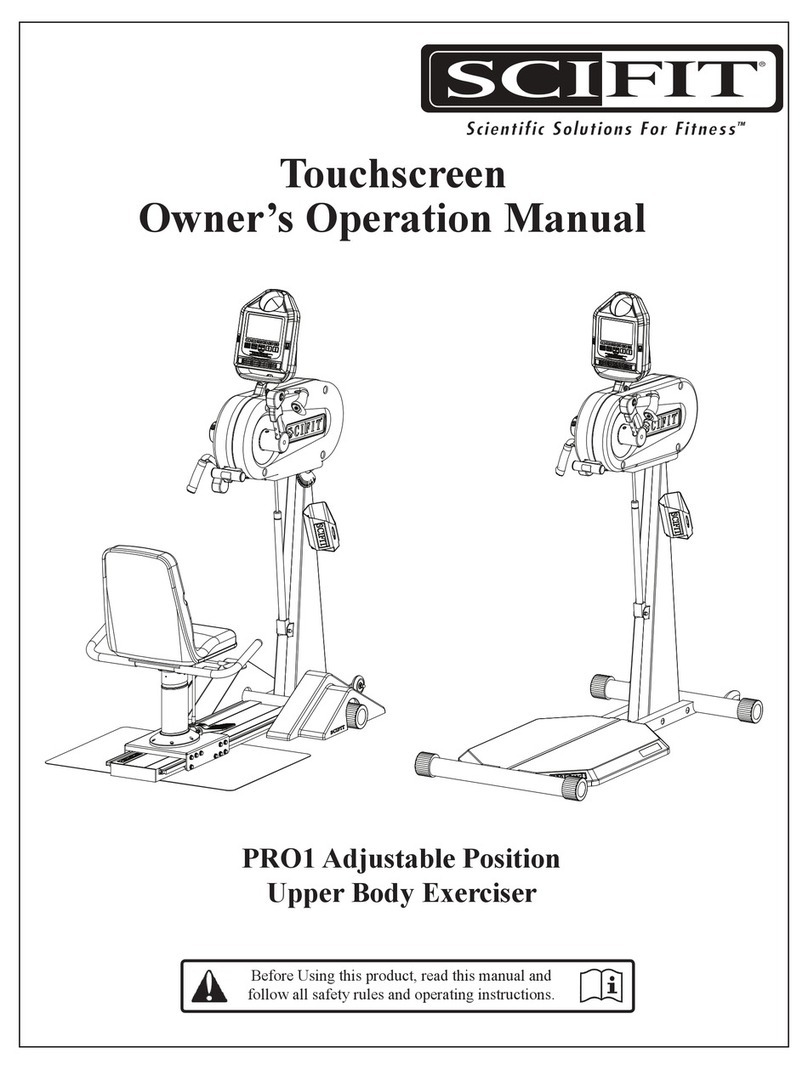
SCIFIT
SCIFIT PRO1 Sport Instructions for use

SCIFIT
SCIFIT TC1000 Series Instructions for use
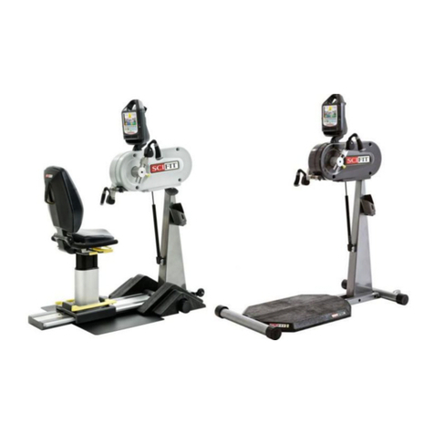
SCIFIT
SCIFIT PRO1XX-DOMHUR User manual
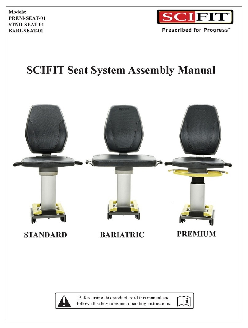
SCIFIT
SCIFIT STANDARD User manual

SCIFIT
SCIFIT PRO1 Sport User manual
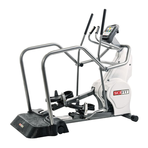
SCIFIT
SCIFIT SXT7000 Parts list manual

SCIFIT
SCIFIT PRO2 User manual
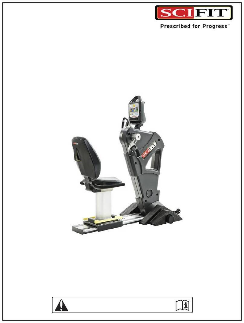
SCIFIT
SCIFIT PRO1030-INT User manual

SCIFIT
SCIFIT PRO1000 Sport User manual
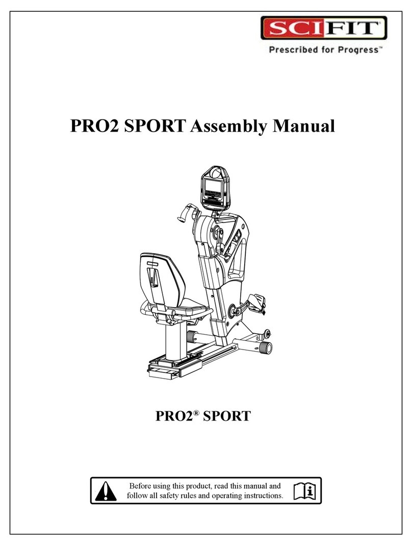
SCIFIT
SCIFIT PRO2 User manual
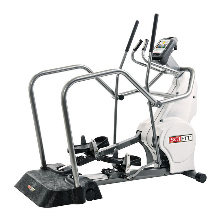
SCIFIT
SCIFIT SXT7000 User manual
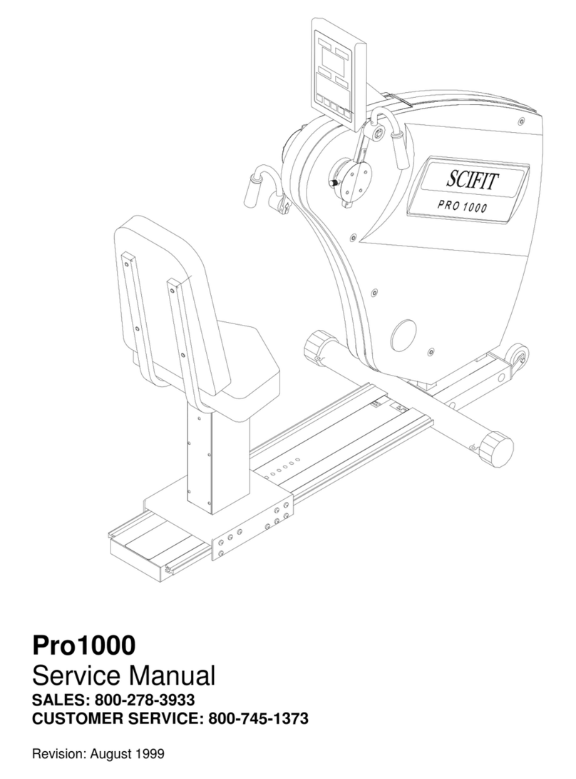
SCIFIT
SCIFIT PRO1000 Sport User manual
SCIFIT
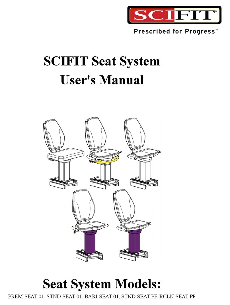
SCIFIT PREM-SEAT-01 User manual

SCIFIT
SCIFIT PRO2 User manual

SCIFIT
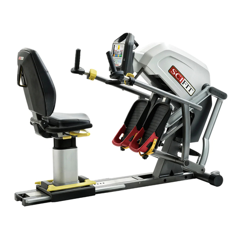
SCIFIT PRO1 Sport User manual
SCIFIT
SCIFIT SONE Series User manual

SCIFIT
SCIFIT PRO2 Instructions for use
Popular Fitness Equipment manuals by other brands

G-FITNESS
G-FITNESS AIR ROWER user manual

CAPITAL SPORTS
CAPITAL SPORTS Dominate Edition 10028796 manual

Martin System
Martin System TT4FK user guide

CIRCLE FITNESS
CIRCLE FITNESS E7 owner's manual

G-FITNESS
G-FITNESS TZ-6017 user manual

Accelerated Care Plus
Accelerated Care Plus OMNISTIM FX2 CYCLE/WALK user manual


