Scotsman Air and Water Cooled C1448 User manual

Models C1448, C1848, C2148W
Installation and User's Manual
Manuale dell’utente e di
installazione
Manual de instalación y del
usuario
Installation et Manuel de
l’utilisateur
Installations- und
Bedienungsanleitung


Introduction
The design of this modular cuber is the result of
years of experience and testing. Standard features
include front accessible indicator lights and on-off
switches that provide the user with fast access to
critical information and easy operational control.
When desired, optional controls can add features
like ultrasonic bin ice level sensing, seven day
programmable bin ice level setting, remote lock out
and more.
This installation and user manual is divided into
three main sections: Installation, which provides
the trade person with the information needed to set
up and install this product; Use and Operation,
which provides the user with the information to use
the product; and Maintenance, which provides the
user with the information needed keep it operating
efficiently.
Note any Caution or Warning symbols when they
appear on the product or in this manual. They
indicate potential hazards.
November 2006
Page 1
C1448, C1848, C2148W
Air and Water Cooled User Manual
Table of Contents
Installation: Product Specifications ....................................Page 2
Product Information ............................................Page 3
Water ...................................................Page 4
Panel Removal ..............................................Page 5
Uncrate and Set Up ...........................................Page 6
Plumbing Requirements .........................................Page 7
Electrical .................................................Page 8
Initial Start Up ..............................................Page 9
Adjustments ...............................................Page 10
Use and Operation ............................................Page 11
Water flush setting ............................................Page 12
Switches .................................................Page 13
Options and Other Information ......................................Page 14
Cleaning, Sanitation and Maintenance ..................................Page 15
What to do before calling for service ...................................Page 16

Installation: Product Specifications
Location Limitations: The product is designed to be
installed indoors, in a controlled environment. Air
cooled models discharge very warm air into the
room out the back. Space must be allowed at the
left side and back for air intake and discharge.
Water cooled models discharge warm water into
the building’s drain. Space needs to be provided on
both sides and above for service access.
Space Limitations
Note: Although the machine will function, ice
capacity of air cooled machines will be significantly
reduced with minimal clearance at the sides, back
and top. Some space is recommended for service
and maintenance purposes on all models.
6" of space at the sides and back are required for
adequate operation. To get the most capacity,
locate the machine away from heat producing
appliances and heating ducts. Provide several feet
of space to the left for maximum ice capacity.
Walls or other large machines near to the ice
machine might also cause a reduction in ice
capacity. One foot behind and two feet above will
be required to make rated capacity.
Airflow is in the front, in the left side, out the back
(as viewed from the front).
Environmental Limitations
Minimum Maximum
Air temperature 10oC. 40oC.
Water
temperature 4oC. 40oC.
Water pressure 1 bar 5 bar
Power supply – acceptable voltage ranges
Minimum Maximum
230 volt model 207 volts 253 volts
Warranty Information
The warranty statement for this product is provided
separately from this manual. Refer to it for
applicable coverage. In general warranty covers
defects in material or workmanship. It does not
cover maintenance, corrections to installations, or
situations when the machine is operated in
circumstances that exceed the limitations printed
above.
November 2006
Page 2
C1448, C1848, C2148W
Air and Water Cooled User Manual
Airflow Direction

Product Information
The product is a modular cuber. That type of
machine is designed to be placed on an ice storage
bin or an ice dispenser. Many installations only
require the matching bin, but some also require an
adapter to be placed between the bin and the
cuber or between the dispenser and the cuber.
This product cannot be stacked. See the chart
for application information.
Model Number Description
Example:
•C1448MA-6A
•C= cuber
•14= nominal ice capacity in 100s of pounds
•48= nominal width of cabinet
•S= Cube size. S=small or half dice cube.
M=medium or full dice cube
•A=Condenser type. A=air cooled. W=water
cooled
•-6=230/50/1
•A=Series revision code. A=first series
Note: In some areas of this manual model numbers
may include only the first five characters of the
model number, meaning that the cube size,
condenser type and voltage differences are not
critical to the information listed there.
Options:
There are several field-installed options that can be
installed at initial start up or later. They include:
•Vari-Smartäadjustable ice level system.
•SmartBoardäadvanced feature control.
Some installations require bin adapters. See the
table below.
Standard Bin Applications - Adapter
information.
Model BH900*, B948S
BH1100,
BH1300,
BH1600
C1448,
C1848,
C2148
Direct Fit, no
adapter needed
No adapter
needed
* Note. If previously equipped with stainless steel
baffle, KBAFFLE3, remove and replace with
original plastic baffle.
Other Bins & Applications:
Note the drop zone and ultrasonic sensor locations
in the illustrations.
Scotsman assumes no liability of responsibility of
any kind for products manufactured by Scotsman
that have been altered in any way, including the
use of any part and/or other components not
specifically approved by Scotsman.
Scotsman reserves the right to make design
changes and/or improvements at any time.
Specifications and design are subject to change
without notice.
November 2006
Page 3
C1448, C1848, C2148W
Air and Water Cooled User Manual

Water
The quality of the water supplied to the ice machine
will have an impact on the time between cleanings
and ultimately on the life of the product. There are
two ways water can contain impurities: in
suspension or in solution. Suspended solids can be
filtered out. In solution or dissolved solids cannot
be filtered, they must be diluted or treated. Water
filters are recommended to remove suspended
solids. Some filters have treatment in them for
suspended solids. Check with a water treatment
service for a recommendation.
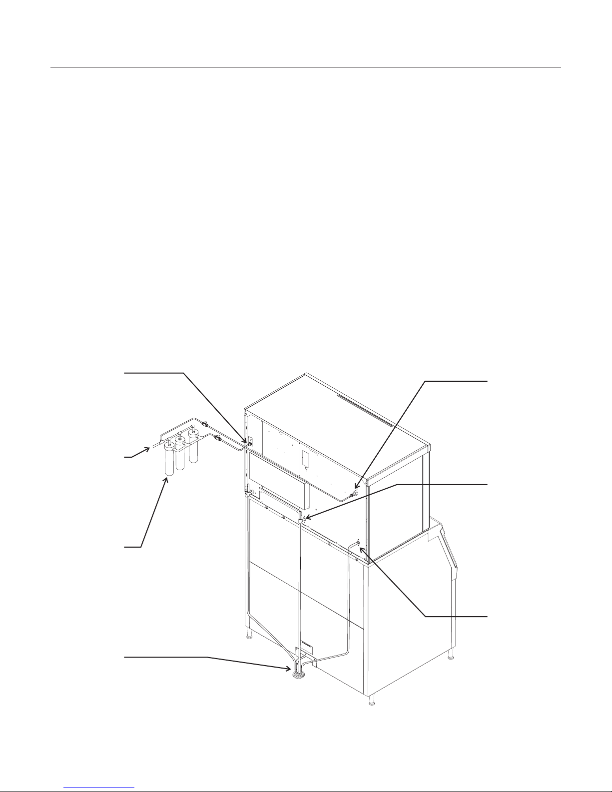
Scotsman filters:
A triple head filter is recommended for the potable
water. Either the Scotsman SSM3 taste and odor
filter system, or the ADS-AP3 Aqua Patrol system.
RO water. This machine can be supplied with
Reverse Osmosis water, but the water conductivity
must be no less than 10 microSiemens/cm.
Condenser Water Supply - filtration not
recommended for this water supply
Potential for Airborne Contamination
Installing an ice machine near a source of yeast or
similar material can result in the need for more
frequent sanitation cleanings due to the tendency
of these materials to contaminate the machine.
Most water filters remove chlorine from the water
supply to the machine which contributes to this
situation. Testing has shown that using a filter that
does not remove chlorine, such as the Scotsman
Aqua Patrol, will greatly improve this situation,
while the ice making process itself will remove the
chlorine from the ice, resulting in no taste or odor
impact. Additionally, devices intended to enhance
ice machine sanitation, such as the Scotsman
Aqua Bullet, can be placed in the machine to keep
it cleaner between manual cleanings
Water Flush
Cube ice machines use more water than what ends
up in the bin as ice. While most water is used
during ice making, a portion is designed to be
drained out every cycle to reduce the amount of
hard water scale in the machine. That’s known as
water flush, and an effective flush can increase the
time between needed water system cleaning.
In addition, this product is designed to
automatically vary the amount of water flushed
based on the purity of the water supplied to it. The
water flush rate can also be set manually.
Adjustments of flush due to local water conditions
are not covered by warranty.
November 2006
Page 4
C1448, C1848, C2148W
Air and Water Cooled User Manual

Panel Removal
1 Locate and loosen the two screws at the front
edge of the top panel.
2 Pull the front panel out at the top until it clears
the top panel.
3 Lift the front panel up and off the machine.
4 Remove two screws at front edge of top
panel.
5 Lift up the front of the top panel, push it back
an inch, then lift to remove.
6 Locate and loosen the screw holding each
side panel to the base.
7 Pull the side panel forward to release it from
the back panel.
Switch Bezel
All models ship with the On and Off switches front
accessible. if desired, the On and Off switches can
be covered up to prevent unauthorized use by
changing the bezel in the front panel's trim strip. A
cover-up bezel ships loose with the machine.
To change bezels: Remove the front panel and
refer to the instruction label on the inside of the
front panel. Push snaps of the standard bezel in
and pull the bezel out of the front panel. Locate
other bezel. Push into trim strip from the front until
it snaps into place. Return the front panel to its
original position and secure it to the cabinet.
November 2006
Page 5
C1448, C1848, C2148W
Air and Water Cooled User Manual
Panel Removal
6
1
5
5

Uncrate and Set Up
Begin with unpacking the ice storage bin. Remove
the carton, and using part of the carton as a
cushion, tip the bin on its back to remove the skid
and attach the legs or casters.
Note: Turn the leg levelers in all the way and adjust
after the ice machine is on top and in its selected
location.
Return the bin to an upright position. Check the bin
top gasket for gaps and tears, fill any in with food
grade sealant prior to placing the ice machine on
the bin.
Install the bin top adapter if one is required for the
application.
If the ice machine has not been unpacked, do so
now. Remove the carton from the skid. Lift the ice
machine off the skid directly onto the bin.
Note: The machine is heavy! Use a mechanical
hoist if necessary.
Secure the ice machine to the bin with the
hardware provided (two metal straps and 4 bolts).
Level the bin and ice machine using the adjustment
part of the legs.
Bin Recycling
Many times an ice machine head will be replaced,
while the existing ice storage bin will be reused.
This is an acceptable practice, if some precautions
are taken:
•The used bin must be in good condition.
Broken doors, hinges, or warped walls are
reason for considering a new bin.
•The used bin top edge gasket must be
replaced. Water leaks could occur if the
gasket tape is not replaced.
•The used bin should be the proper size for
the ice machine head.
November 2006
Page 6
C1448, C1848, C2148W
Air and Water Cooled User Manual

Plumbing Requirements
All models require connection to cold, potable
water. A hand actuated valve within site of the
machine is required. Air cooled models have a
single 3/4 gas BSPP inlet water connection.
Water cooled models have the same inlet fitting
plus an additional 3/8” FPT condenser inlet water
connection.
Drains
All models require drain tubing to be attached to
them. Air cooled models have a single ¾” FPT
drain fitting in the back of the cabinet. Water cooled
models have the same fitting plus an additional ½”
FPT drain fitting in the back of the cabinet.
Install new tubing when replacing a prior ice
machine, as the tubing will have been sized for the
old model and might not be correct for this one.
1 Connect water supply to water inlet fittings.
2 Connect drain tubing to drain fittings.
3 Route the drain tubing to building drain. Follow
local codes for air gap.
Use rigid drain tubes and then route them
separately – do not Tee into the bin’s drain or, if
water cooled, Tee the condenser drain into the
reservoir or bin drain.
Vent the reservoir drain. A vertical vent at the back
of the drain, extended about 200 mm will allow the
gravity drain to empty and also keep any surges
during draining from discharging water.
Horizontal runs of drain tubing needa6mmfall per
meter of run for proper draining.
Follow all applicable codes.
November 2006
Page 7
C1448, C1848, C2148W
Air and Water Cooled User Manual
Water Supply and Drain Connections
Optional
Water Filters
Water Cooled
Condenser
Inlet
Water Cooled
Condenser
Drain
Water Inlet
Connection
Potable Water
Supply
Reservoir
Drain
Floor Drain

Electrical
The machine is not supplied with a power cord, one
must either be field installed or the machine
hard-wired.
The dataplate on the back of the cabinet details the
power requirements, including voltage, phase and
maximum fuse size. Extension cords are not
permitted. Use of a licensed electrician is
recommended.
Electrical connections are made inside the junction
box in the back panel of the ice machine.
1 Remove the junction box cover and route the
power cord through the access hole and
properly attach the power supply wires to the
leads in the junction box.
2 Install a field supplied strain relief per code.
Attach a ground wire to the ground connection
in the junction box.
3 Check voltage when complete.
4 Return the junction box cover to its original
position and secure with the original screws.
Follow all applicable codes.
Final Check List
After connections,
1 Wash out the bin. If desired, the interior of the
bin could be sanitized.
2 Locate the ice scoop (if supplied) and have it
available for use when needed.
Final Check List:
1 Is the unit located indoors in a controlled
environment?
2 Is the unit located where it can receive
adequate cooling air?
3 Has the correct electrical power been supplied
to the machine?
4 Have all the water supply connections been
made?
5 Have all the drain connections been made?
6 Has the unit been leveled?
7 Have all unpacking materials been removed?
8 Is the water pressure adequate?
9 Have the drain connections been checked for
leaks?
10 Has the bin interior been wiped clean or
sanitized?
11 Have any water filter cartridges been replaced?
12 Have all required kits and adapters been
properly installed?
November 2006
Page 8
C1448, C1848, C2148W
Air and Water Cooled User Manual
Power
Supply
Wires
Ground Wire
Connection
Install
Strain
Relief

Initial Start Up
1 Remove front panel. Check machine for any
packing or wires rubbing moving parts. Note
location of control board in upper left corner of
the machine’s front.
2 Remove tape securing each curtain to its
evaporator.
3 Switch on the electrical power to the machine.
Observe that some of the control’s indicator
lights glow and its display shows O.
4 Open the water supply valve.
5 Push and release the ON button. The indicator
light will begin to blink F.
The flush valve will open and the water pump will
start. The inlet water valve will open to add water to
the reservoir. After a few seconds the flush valve
will close and the water pump will stop. Water will
flow into the machine until the reservoir is full. The
hot gas valves and harvest assist devices will
activate then the compressor and water pump will
start. If its an air cooled model the fan(s) motors
will begin to turn. The display will show a
continuous F. Five seconds later the hot gas valves
will close and the harvest assist device will return
to its standby position. Warm air will be discharged
from air cooled models.
6 Observe the Ready for Harvest indicator light.
It may blink early in the cycle, that is normal.
The control will ignore that signal for the first 6
minutes of freeze.
7 During the Freeze cycle open and close the
curtains. The SW1 and SW2 lights on the
control board will blink ON when each curtain is
opened and OFF when closed.
Note: Moving a curtain during the Freeze cycle has
no affect on the control, but will cause water to flow
into the cube chute.
8 When the ice has frozen enough, the Ready for
Harvest indicator light will be on steady. After
it’s been on steady for a few seconds Harvest
will begin.
9 The display shows an H.
The hot gas valves open, the air cooled fan motors
shut off and the harvest assist mechanisms are
activated. The flush valve opens to drain some
water, when it does the inlet water valve opens to
refill the reservoir. After a few seconds the flush
valve closes but the inlet water valve continues to
fill the reservoir. Harvest continues until the ice is
released as a unit and forces the curtain to open.
When both curtains re-close the controller returns
the unit to a freeze cycle.
10 Check the ice harvested for proper bridge
thickness. The ice bridge is factory set at 3/16
inch. If needed, adjust bridge thickness. Do
NOT make it too thin.
11 Determine the water flush setting from the table
below. If desired, change the setting to
accommodate the local water conditions.
12 Return the front panel to its normal position
and secure it to the machine.
13 Instruct the user in the operation of the
machine and its maintenance requirements.
14 Fill out and mail warranty registration form.
Typical Ice Making Cycle Times (minutes).
Listed times are for clean machines in proper
installations. Cycle length at start up will be longer
until the system stabilizes.
Model 21oC. air /
10oC. water
32oC. air /
21oC. water
C1448A 12-14 14-16
C1448W 13-15 14-16
C1848A 9-11 12-14
C1848W 9-11 10-12
C2148W 9-11 10-12
November 2006
Page 9
C1448, C1848, C2148W
Air and Water Cooled User Manual

Adjustments
Bridge Thickness - For Service Tech Only
1 Push and hold Off till the machine stops.
2 Remove evaporator cover.
3 Remove curtain.
4 Use a box wrench and rotate the bridge
thickness adjustment screw in 1/8 turn
increments CW to increase bridge thickness.
Rotate CCW to decrease bridge thickness.
Caution: Do not make the bridge too thin or the
machine will not harvest properly. Bridge thickness
adjustments are not covered by warranty.
5 Return curtain to its normal position.
6 Push and release the On button. Check next
harvest of ice. Repeat steps 1-6 if needed.
November 2006
Page 10
C1448, C1848, C2148W
Air and Water Cooled User Manual
Ice Bridge Thickness Measurement
Too Big Too Small
Just Right for
Small Cube
3-4 mm
bridge
Ice Thickness Sensor
Just Right for
Medium Cube
Note: Water cooled models, the refrigeration
system discharge pressure is factory set at 245
PSIG, which should yield a freeze cycle discharge
water temperature of about 105-110 degrees F.
Adjust if necessary.

Use and Operation
Once started, the ice machine will automatically
make ice until the bin or dispenser is full of ice.
When ice level drops, the ice machine will resume
making ice.
Caution: Do not place anything on top of the ice
machine, including the ice scoop. Debris and
moisture from objects on top of the machine can
work their way into the cabinet and cause serious
damage. Damage caused by foreign material is not
covered by warranty.
There are four indicator lights at the front of the
machine that provide information on the condition
of the machine.
Indicator Lights:
•Power
•Status
•Water
•Clean
Light indicators & their meanings
Indicator Lights & Their Meanings
Power Status Water De-Scale & Sanitize
Steady Green Normal Normal – bin full or making ice - -
Blinking Green Self Test
Failure Switching on or off - -
Blinking Red - Diagnostic shutdown or, if making
ice, temperature sensor failure
Lack of
water -
Yellow - - - Time to de-scale
and sanitize
Blinking Yellow - - - In Cleaning mode
Light off No power Switched off Normal Normal
All Blinking Unit remotely locked out – check with leasing company
If the Water light is on, the machine has sensed a
lack of water. Check the water supply to the
machine. The water may have been shut off or the
water filter cartridges need to be changed.
November 2006
Page 11
C1448, C1848, C2148W
Air and Water Cooled User Manual
If the De-Scale light is on, the machine has
determined that it may need to be cleaned. Contact
an authorized Scotsman service agent and have
the machine cleaned, de-scaled and sanitized.
Note: A Component Indicator Light switches ON to
indicate that the component is operating.
Note: There are two Curtain Switch lights, SW1 and
SW2. A curtain switch light is ON when a curtain is
either open or not present.

Water flush setting
The water flush is factory set to the automatic
position, suitable for most water conditions. The
setting can be changed to one of 5 manual settings
or left on automatic.
Flush
setting
1-
Minimum
2-
Moderate
3-
Standard 4 - Heavy 5-
Maximum A - Automatic
Water
Type
RO water
or
equivalent
Factory
Setting for
typical
water
High TDS
water
Any with
conductivity not
less than 10
microSiemens/cm
To set:
1 Switch the machine OFF by holding the Off
button in until a number or the letter Ashows
on the display.
2 Press and release the On button repeatedly
until the number on the display corresponds to
the desired setting.
3 Press and release the Off switch again to
return to the normal control state.
November 2006
Page 12
C1448, C1848, C2148W
Air and Water Cooled User Manual
Power
Status
Water
OffDe-Scale
On

Switches
The panel in the front of the machine can be flipped
up to access two switches – on and off.
•To switch the machine OFF, push and
release the Off button. The machine will shut
off at the end of the next cycle.
•To switch the machine ON, push and release
the On button. The machine will go through a
start up process and then resume ice
making.
Control Options
There are two optional, field installed controls that
can be on this machine.
•Vari-Smart (KVS) Adjustable ice level control
•SmartBoard (KSB) Advanced Feature control
Adjustable ice level control
When this option is present there is an adjustment
post and an additional indicator light to the right of
the four indicator lights mentioned above. The
ultrasonic ice level control allows the use to control
the point that the ice machine will stop making ice
before the bin or dispenser is full. Reasons for this
include:
•Seasonal changes in ice used
•Planning to sanitize the bin
•Faster turnover for fresher ice
•Certain dispenser applications where
maximum ice level is not desired
Use of control
There are several positions the ice level can be set
to, including Off (knob and label indicators lined
up), where it fills the bin until the standard bin
control shuts the machine off. See the kit’s
instructions for complete details.
Rotate the adjustment post to the desired ice level.
The machine will fill up to that level and when it
shuts off the indicator light next to the adjustment
post will be On.
Note: Ice will build up in the bin or dispenser at an
angle, the distances listed above will be from the
sensor to the top of the ice directly beneath it.
The actual distance between the highest point of
the ice may be closer or further away, depending
upon the angle of the ice.
November 2006
Page 13
C1448, C1848, C2148W
Air and Water Cooled User Manual
Power
Status
Water
OffDe-Scale
On
02-4294-01 Rev. A.
Adjust Ice Level
L
o
w
e
r
Bin
Full
VariSmart Control Area

Options and Other Information
SmartBoard
When this option is present there is an additional
display panel in the area below the main control
board. It is not visible when the front panel is on.
The SmartBoard’s features include:
•Seven day programmable ice level setting
when used with the optional Vari-Smart ice
level control
•Recording of machine operation, including
cycle time.
•Calculation of average cycle time
•Recall of malfunctions with the time they
occurred.
Ice
The cuber drops ice in large sections. That ice will
break up into random parts as it falls into the bin,
but some large sections may remain on top of the
ice in the bin. When removing ice, tap the groups of
ice with an ice scoop to separate them into smaller
units. In a dispenser, this ice will break up into
mostly individual cubes as the dispense
mechanism moves the ice.
Heat
Air cooled models will generate heat when in
operation. That heat is discharged out the back of
the cabinet.
Noise
The ice machine will make noise when it is in ice
making mode. The compressor, fan motors if air
cooled and water pump all produce some sound. It
is also normal to hear some cracking just before
the harvest cycle begins. In addition, during the
harvest cycle the harvest assist solenoid will click
twice as it pushes the ice out and returns to its
normal position. The ice harvests as a unit or slab,
which makes some noise when it impacts the bin or
dispenser. These noises are all normal for this
machine.
November 2006
Page 14
C1448, C1848, C2148W
Air and Water Cooled User Manual
SmartBoard Advanced Feature Control™
See Instructions for Available Features
34 SEL
02-4293-01 Rev A.
ENTER
ESC

Cleaning, Sanitation and Maintenance
This ice system requires three types of
maintenance:
•Remove the build up of mineral scale from
the ice machine’s water system and sensors.
•Sanitize the ice machine’s water system and
the ice storage bin or dispenser.
•Clean or replace the air filter and clean the
air cooled condenser (air cooled models
only).
It is the User’s responsibility to keep the ice
machine and ice storage bin in a sanitary
condition.
Sanitize the ice storage bin as frequently as local
health codes require, and every time the ice
machine is cleaned and sanitized.
The ice machine’s water system should be
cleaned and sanitized a minimum of twice per
year. This is critical to the proper operation of
the ice machine. Contact you local authorized
service agent for water system cleaning.
.Air cooled condenser filter
1. Pull air filter(s) forward from side panel.
2. Wash the dust and grease off the filter.
3. Return it to its original position.
Do not operate the machine without the filter in
place except during cleaning.
Air cooled condenser
If the machine has been operated without a filter
the air cooled condenser fins will need to be
cleaned.
They are located under the fan blades. The
services of a refrigeration technician will be
required to clean the condenser.
Exterior Panels
The front and side panels are durable stainless
steel. Fingerprints, dust and grease will require
cleaning with a good quality stainless steel cleaner.
Water filters
If the machine has been connected to water filters,
check the cartridges for the date they were
replaced or for the pressure on the gauge. Change
cartridges if they’ve been installed more than 6
months or if the pressure drops too much when the
ice machine fills with water.Air cooled condenser
filter
1 Pull air filters from their louvered mounts.
2 Wash the dust and grease off the filter.
3 Return them to their original positions.
Do not operate the machine without the filter in
place except during cleaning.
November 2006
Page 15
C1448, C1848, C2148W
Air and Water Cooled User Manual
Air Filter Removal
Filter
Filter

What to do before calling for service
Reasons the machine might shut itself off:
•Lack of water.
•Freeze cycle takes too long.
•Harvest cycle takes too long.
•High discharge temperature.
•Controller self test failure.
Check the following:
1. Has the water supply to the ice machine or
building been shut off? If yes, the ice machine will
automatically restart within 25 minutes after water
begins to flow to it.
2. Has power been shut off to the ice machine? If
yes, the ice machine will automatically restart when
power is restored.
3. Has someone shut the water off to a water
cooled unit? If yes, the ice machine may need to be
manually reset.
4. Is the curtain open because some ice is stuck
under it? If so, remove the ice and the machine
should start in a few minutes.
Note: Curtain can be removed & replaced anytime
the machine is in a standby mode or when it is in a
freeze cycle. Removal of the curtain during harvest
terminates harvest at that point and, if left off, will
result in the machine shutting off.
To Manually Reset the machine.
•Push and release the Off button.
•Push and release the On button.
To Shut the Machine Off:
1. Push and hold the Off button for 3 seconds or
until the machine stops.
November 2006
Page 16
C1448, C1848, C2148W
Air and Water Cooled User Manual


Introduzione
Il design di questo fabbricatore modulare di ghiaccio
a cubetti è il risultato di anni di esperienza e collaudi.
Le caratteristiche standard includono spie indicatrici
e interruttori di accensione e spegnimento accessibili
dal lato anteriore, che consentono un rapido accesso
ai dati fondamentali e semplificano il controllo operativo.
Con sistemi di controllo opzionali è possibile aggiungere
ulteriori funzioni, tra cui un sensore del livello del
ghiaccio a ultrasuoni, l’impostazione del livello del
ghiaccio programmabile per sette giorni, il blocco
in remoto dell’unità.
Questo manuale dell’utente e di installazione èsuddiviso
in tre sezioni principali: Installazione, che fornisce al
rappresentante di vendita le informazioni necessarie
per posizionare e installare questo prodotto; Uso e
Funzionamento, che fornisce all’utente le informazioni
necessarie per utilizzare il prodotto; e Manutenzione,
che fornisce all’utente le informazioni necessarie per
preservare il corretto funzionamento dell’apparecchio.
Osservare scrupolosamente le informazioni contraddistinte
dai simboli di attenzione o avvertenza riportate sul prodotto
o in questo manuale. Tali informazioni indicano potenziali
pericoli.
Novembre 2006
Pagina 1
Manuale dell'utente per i modelli
C1448, C1848 e C2148W raffreddati ad aria o ad acqua
Sommario
Installazione: Specifiche tecniche ....................................... Pagina 2
Informazioni sul prodotto ........................................... Pagina 3
Acqua ..................................................... Pagina 4
Rimozione dei pannelli ............................................ Pagina 5
Disimballaggio e installazione ......................................... Pagina 6
Requisiti idraulici ............................................... Pagina 7
Collegamenti elettrici ............................................. Pagina 8
Accensione iniziale .............................................. Pagina 9
Regolazioni .................................................. Pagina 10
Uso e Funzionamento ............................................. Pagina 11
Impostazione scarico acqua ......................................... Pagina 12
Interruttori ................................................... Pagina 13
Componenti opzionali e ulteriori informazioni ................................. Pagina 14
Pulizia, igienizzazione e manutenzione .................................... Pagina 15
Operazioni da svolgere prima di rivolgersi all’assistenza ........................... Pagina 16
Other manuals for Air and Water Cooled C1448
3
This manual suits for next models
2
Table of contents
Languages:
Other Scotsman Air Conditioner manuals
Popular Air Conditioner manuals by other brands

Panasonic
Panasonic CS-TU12VKYF Series CS-TU18VKYF Series operating instructions

Friedrich
Friedrich Uni-Fit Thru-the-Wall Series Service manual

Mitsubishi Electric
Mitsubishi Electric Mr. Slim PCA-RP-HAQ installation guide

York
York DRCS0181BE Technical guide

Mitsubishi Electric
Mitsubishi Electric MSZ-WR NA Series Service manual

INVENTOR
INVENTOR V6FI-60 user manual